Table of Contents
Advertisement
Quick Links
WARNING
following:
• Follow all applicable electrical codes.
• Turn off power at main source before making any electrical connections or servicing the unit.
• To reduce the risk of electric shock, injury or death disconnect unit from power supply
• Follow the instructions or risk of serious injury or death could occur!
UV EXPOSURE & PROTECTION:
UV-A and UV-B radiation can have adverse short and long term effects on the eyes and skin. Never
look directly at a UV lamp that is connected to a power source. Avoid UV skin exposure at all times.
NOTICE
Follow all codes and regulations that apply to the design, installation and use
of suction outlet fittings.
295 East Corporate Place • Suite 100 • Chandler, AZ 85225
Toll Free: 1.800.621.5886 • Phone: 480.893.7607 • Fax: 480.753.3397
Paramount@1Paramount.com • www.1Paramount.com
004-422-0003-00 REV 071416
IMPORTANT SAFETY INSTRUCTIONS: READ
COMPLETELY BEFORE PROCEEDING.
When using this electrical equipment, basic safety
precautions should always be followed, including the
To Installers: Read and follow these
instructions. Give these instructions to the
facility owner to keep for future reference.
Pool, Spa & Pond
Water Sanitizer 4BJ1
EPA Registered
#084221-AZ-001
INSTALLATION &
OPERATIONS MANUAL
Advertisement
Table of Contents

Related Manuals for Paramount Fitness Ultra UV


Summary of Contents for Paramount Fitness Ultra UV
- Page 1 INSTALLATION & OPERATIONS MANUAL IMPORTANT SAFETY INSTRUCTIONS: READ WARNING COMPLETELY BEFORE PROCEEDING. When using this electrical equipment, basic safety precautions should always be followed, including the following: • Follow all applicable electrical codes. • Turn off power at main source before making any electrical connections or servicing the unit. •...
- Page 2 Signal Words and Symbols Used In This Manual This Owner’s Manual and Installation Guide contains specific precautions and symbols to identify safety- related information. You will find DANGER, CAUTION, WARNING and NOTICE symbols which require special attention. Please read them carefully and follow these precautions as indicated! They will explain how to avoid hazards that may endanger you or persons using or maintaining your pool or spa.
-
Page 3: Table Of Contents
Quartz Tube Maintenance ............................12 Scheduled UV Lamp(s) Replacement ........................14 Lamp Replacement Procedure ..........................14 Normal Operation Configuration for Ultra UV units installed with bypass ...........15 Bypass Operation Configuration for Ultra UV units installed with bypass ..........15 Winterization Of Your Ultra UV Unit ........................15 Troubleshooting ................................16... -
Page 4: Welcome
UV systems for fish ponds. The best advice is to consult a fish pond expert to determine what the flow rate for your pond should be, and use the appropriate sized Ultra UV for that flow rate see “Fig. 1” on... -
Page 5: Pond Sizing Chart
004-422-2023-00 120V w/ 3 UV-C Lamps All capacities are nominal. Note: Multiple Ultra UV units installed in parallel can be used for flow rates beyond those specified herein. (See page 8) * Header size should be 2½” or 3” and split to two 2” pipe headers at the inlet and outlet connections. -
Page 6: Locating The Ultra Uv Unit
NOTE: The use of multiple inlets/outlets will require additional unions. Use the plugs provided with the Ultra UV in the unused inlets and outlets. To install the unions on to the Ultra UV unit, glue and insert the unions spigot end into the inlet and outlet opening selected. Then, using the six plugs provided, glue the plugs into the remaining unused plumbing openings. -
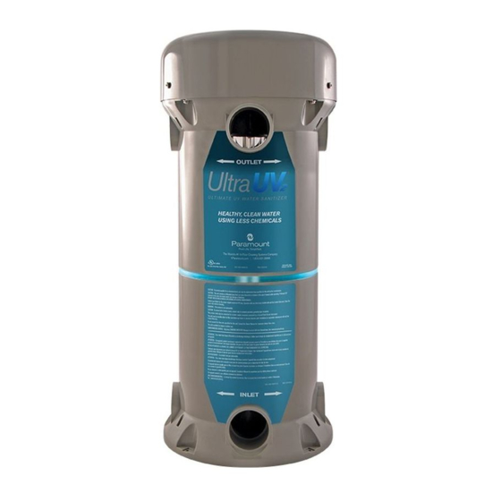
Page 7: Parallel Plumbing Without And With Bypass
The inlet is at the bottom of the unit and the outlet at the top. The maximum operating pressure for the Ultra UV is 20 PSI / 1.38 BAR or 50 PSI / 3.45 BAR. Please refer to the silver label on the unit for max. - Page 8 2 inch Flow Switch (part #004-402-0010-00 for 220v or part #004-421-3824-00 for 120v), must be on the outlet side of the Ultra UV unit and plumbed after the two way valve and before the tee into the return line. Please refer to the instructions supplied with the flow switch for plumbing and wiring.
-
Page 9: Multiple Port Plumbing Without And With Bypass
2 inch Flow Switch (part #004-402-0010-00 for 220v or part #004-421-3824-00 for 120v), must be on the outlet side of the Ultra UV unit and plumbed after the two way valve and before the tee into the return line. Please refer to the instructions supplied with the flow switch for plumbing and wiring. -
Page 10: Gluing Piping To The Uv Unit
(if the unit is plumbed with a bypass) to allow the Ultra UV to be only left at or below the max operating pressure. -
Page 11: System Start-Up
PRESSURE SWITCH The Ultra UV unit is equipped with 1 of 2 types of pressure switches that does not allow the UV lamp(s) Fig. 5 inside the unit to light unless there is at least 5 PSI (0.35 BAR) inside the Ultra UV reactor chamber. -
Page 12: Consumer Operating Instructions
Cleaning the quartz tube: The quartz tube requires cleaning every 6 months to ensure optimum performance. 1. Turn off all power to the ULTRA UV unit and all other pool equipment. Unplug the unit from its power receptacle or turn OFF the circuit breaker that is the ULTRA UV’s power source. - Page 13 Fig. 14 The quartz tube NOTICE is fragile, be sure to handle it with proper care and do not set it down on a hard surface. Do not use abrasive cleaners or pads. 8. Using protective rubber gloves and eye wear use a good shower/tub cleaner or a solution of white vinegar and water to clean the outside of the quartz tube (Fig.
-
Page 14: Scheduled Uv Lamp(S) Replacement
Fig. 23 SCHEDULED UV LAMP(S) REPLACEMENT The UV lamps have a useful life of approximately 13,000 hours and should be replaced at that time. Even though the lamp(s) may be glowing after 13,000 hours of operation they have reached the end of their useful life. -
Page 15: Normal Operation Configuration For Ultra Uv Units Installed With Bypass
To Heater or Pool partial opening of the bypass valve can cause damage to the Ultra UV unit. This instruction applies to all systems with a single Bypass speed or with a variable speed pump. During normal operation the Valve #1 bypass valve #1 should be completely closed and the inlet valve #2 and outlet valve #3 should be full open. -
Page 16: Troubleshooting
THE UV LAMP(S) WILL NOT ILLUMINATE If this occurs upon initial start-up, the problem could be caused by a number of issues. All Ultra UV units come with the pressure switch disabled. Make sure the electric is off, remove the cover and check to see that both wires are connected to the pressure switch. - Page 17 GFCI trip is encountered, plug the Ultra UV unit into the electrical receptacle and make sure the pump is ON. If the GFCI trips, it is an indication that there is a ground fault inside the Ultra UV unit.
-
Page 18: Ultra Uv Part Numbers
ULTRA UV PART NUMBERS Paramount Part# Description 005-422-2009-11 Bonnet 005-422-9005-00 UV Lamp Spring Clip Centering Disc 005-422-5102-00 Quartz Tube Sealing Assembly 005-422-5103-00 Quartz Tube Seal O-Ring, 3 Pack 005-422-9003-00 Program Start Ballast for 1 Lamp 005-422-9004-00 Program Start Ballast for 2 Lamps... - Page 19 Lamp Unit 2" Union Kits 63mm Union Kits Configurations • 1 Lamp unit requires 1 single lamp ballast • 2 Lamp unit requires Optional 1 dual lamp ballast Flow Switch • 3 Lamp unit requires 1 single lamp ballast 1 dual lamp ballast...
Need help?
Do you have a question about the Ultra UV and is the answer not in the manual?
Questions and answers