IBM 360 Manual
Hide thumbs
Also See for 360:
- User manual (118 pages) ,
- Operating manual (48 pages) ,
- Hardware maintenance manual (508 pages)
Table of Contents
Advertisement
Quick Links
IBM
SALES and SYSTEMS GUIDE
IBM BASIC C O U N TER UNIT
COMPONENT D ESCR IPTIO N AND U SER 'S G U ID E
This guide describes the organization and use of the IBM Basic Counter
Unit. The IBM Basic Counter Unit monitors the various activities of a
system and provides data for analyzing a system's performance. Among
the systems that can be monitored are:
IBM System/360
IBM 1800 Data Acquisition and Control System
IBM 1130 Computing System
IBM IN T ER N A L USE O N LY
ZZ22-6953-0
Advertisement
Table of Contents

Related Manuals for IBM 360


Summary of Contents for IBM 360
- Page 1 IBM BASIC C O U N TER UNIT COMPONENT D ESCR IPTIO N AND U SER 'S G U ID E This guide describes the organization and use of the IBM Basic Counter Unit. The IBM Basic Counter Unit monitors the various activities of a system and provides data for analyzing a system's performance.
- Page 2 Changes are periodically made to the specifications herein; any such changes will be reported in subsequent revisions. Requests for copies of IBM publications should be made to your IBM representative or to the IBM branch office servicing your locality. This manual has been prepared by the IBM Systems Development Division, Product Publications, Dept.
-
Page 3: Table Of Contents
Counters S e c tio n ................16 A ppendix C. Probe A ssignm ent Planning Form O ptional A ccessory—IBM 1 0 5 7 /1 0 5 8 Card Punch . Operating P r o c e d u r e s................19 A ppendix D. - Page 4 IBM Internal Use Only IBM 1058 Printing Card Punch Model 2 Attached to IBM Basic Counter Unit...
-
Page 5: Ibm Basic Counter Unit
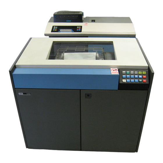
Counter Unit; Figure 2 is an example of a measured system Evaluate programming improvements. profile. The IBM Basic Counter Unit (Frontispiece) measures the various activities of a system and provides data for DESCRIPTION analyzing a system’s performance. - Page 6 IBM Internal Use Only The connection of the IBM Basic Counter Unit to the equipment to be monitored is illustrated in Figure 3. The monitor probe cables, 15 feet each, terminate at a centrally located junction box, close to the units to be monitored.
- Page 7 IBM Internal Use Only ■ ■ ■ I W ÊÊtÊtÊÊ^Êm Bjgiia * % ii» i i « » Figure 4. IBM Basic Counter Unit IBM Basic Counter Unit...
-
Page 8: Operating The Ibm Basic Counter Unit
Punch Go (backlighted) punch operation. The operation punches the contents of 16 Lamp Test (backlighted) counters on four IBM cards. If the punch go pushbutton is inoperative, check the intfc check indicator light. Power-On activates the voltages within the Basic Counter Unit. -
Page 9: Indicator Lights
(Figure 7). Supplied with the probes are adapters that slip on to allow attachment to the pins on the systems or I/O devices being monitored. An example o f the IBM Basic Counter Unit Probe Assignment Planning Form, ZX22-6946, appears in “Appendix C.”... -
Page 10: Junction Box
IBM Internal Use Only Figure 7. Monitor Probe Module Unit and receives power from the Basic Counter Unit for transfer to the monitor probes. Each junction box connects a maximum of ten monitor Unit is supplied with 20 monitor probes with connected probe cables to one signal cable. -
Page 11: Patch Panel Signal Hubs
Patch Panel Signal Hub Evolution diagram (Figure 26). Before wiring the patch panel, the user should plan his work on the IBM Basic Counter Unit Patch The evolution of a signal at a signal hub on the patch panels Panel Planning Form, ZX22-6952 (see “Appendix G”). -
Page 12: Logic Sections
IBM Internal Use Only Connections for the AND Functions location (probe point) on the back panel of the equipment being monitored. A probe point location may be minus (-) The six AND functions are designated A l, A2, A3, A4, A5, or plus (+) as specified by the line name in the ALD pages. - Page 13 True in equals not true out, not true in equals true out. See exclusively. OR1 and OR3 serve as LATCH functions when Figures 14 and 15. the H hub is used with any o f the three OR input hubs. If a Operating the IBM Basic Counter Unit...
- Page 14 IBM Internal Use Only True Input = True Output Set = True until Reset Reset = Not True until Set Not True Input = Not True Output Seek Time Seek Start Wait Wait Wait Seek Complete Figure 19. Example of FANOUT Function...
- Page 15 DCDR OUT hubs may be wired to counter timing decode up to any combination of four true binary inputs or counting hubs depending on the user’s specific applica into one of 16 true hexadecimal outputs (Figure 26). tion. Operating the IBM Basic Counter Unit...
-
Page 16: Counters Section
IBM Internal Use Only Additional Self-Generated True Signals Twenty hubs, designated ACVT BUS, on the test patch panel may be used as a source of self-generated true signals when the supply of +1 (A, B, C, D) and +1 (E, F, G, H) hubs has been exhausted (Figure 26). - Page 17 0 6 0 O— — O 0 - ^ - 0 — G 0 7 0 — H — J F3 IN 20 0----O — K FORCE CARRY Figure 26. Patch Panel Image Card Operating the IBM Basic Counter Unit...
-
Page 18: Optional Accessory - Ibm 1057/1058 Card Punch
IBM 1050 Data Communication 11 columns. Formatting of the other three counters in the System , Principles o f Operation, GA24-3474 and IBM 1050 same card is effected in the same manner. Operator’ s Guide, GA24-3125. - Page 19 IBM Internal Use Only Figure 27. IBM 1057/1058 Card Punch Operating Procedures...
- Page 20 1 J 1 4 J 6 7 I 9 10 1 1 1J 13 14 15 It 17 II 18 20 21 22 23 24 25 28 27 2« 79 30 31 32 33 34 35 36 37 38 39 40 4 1 42 4 3 44 45 46 47 48 49 50 5 1 57 53 54 55 56 57 51 59 60 > 1 62 63 64 (S H 67 H 69 70 7 1 72 73 74 75 79 77 79 79 10 Figure 29. Example o f Program Card Optional Accessory-IBM 1057/1058 Card Punch...
-
Page 21: Testing Procedures
IBM Internal Use Only Testing Procedures This section contains testing procedures for the IBM Basic High Speed Count 2 Test Counter Unit and the IBM 1057/1058 Card Punch. 1. Activate TEST 1 and FORCE CARRY 5A hubs. 2. Press MACHINE RESET. -
Page 22: Operational Patch Panel Test
IBM Internal Use Only 5. Single step the counters by repeatedly pressing START. A program card must be installed in the card punch. The Check that all counters contain the same value after card must allow the punch interface to control 64 columns each impression. - Page 23 Total Compute is the signal present when bit number 14 of Example 1 the program status word (PSW) is off, indicating that the During the processing of a job or jobs on System/360, the processor is executing instructions. CPU either overlaps or non-overlaps the I/O channels.
- Page 24 IBM Internal Use Only Patch Panel Work Sheet Total Elapsed Time Any Channel Busy Compute and Any Channel Overlap Total Compute = Not True = Hold = Set Figure 31. Wiring for Example 1 The signals from selector channel 1, selector channel 2,...
- Page 25 72 .2 Wait Example 2 12.9 Wait and Any IBM System/360 has one or more selector channels and a Channel Busy multiplexer channel. These channels can operate at differ 59.3 Wait Only ent times or channel operations can overlap each other.
- Page 26 IBM Internal Use Only Patch Panel Work Sheet Total Elapsed Time Total Compute Sel I Busy Sel II Busy Mpx Busy Any Chan Busy Sel/Sel Overlap = Not True = Hold = Set Figure 33. Wiring for Example 2 Patch Panel Work Sheet...
- Page 27 Selector channel 1 busy The measured system function can also be expressed in Example 4 percentages: The IBM 2314 Direct Storage Facility Model A1 or 1 395.0 seconds Total elapsed time 100.0% contains eight separate modules. In a case study, the IBM Total wait 161.6 seconds...
- Page 28 IBM Internal Use Only Patch Panel Work Sheet ^N5j-0-0-^, ^ To Start Hub Signal _ T ^ Input Counter Total Elapsed 2314 Time Modules Total Time Any Chan Busy ►To Stop Hub — **^*«.^^»^ _ Q ~jF4j— O — O...
-
Page 29: Appendix A. Primary Sources
IBM Internal Use Only Appendix A. Primary Sources Line Name True Function 2040 Processing Unit KH142 HOLD CONDITION Manual (No line name available) KH171 Wait State Not Memory Protect Key 1, Current KUO 11 +CPU TAG REG BIT 3 PSW Bit 11 Off... - Page 30 IBM Internal Use Only True Function Line Name Supervisor State KS261 +MONITOR BIT PSW 15 Processor Cycles to Support I/O Data Transfer - I/O RTNE MODE KE311 Main Storage Not Cycling +ALLOW WRITE MA031 Selector Channels 1 ,2 ,3 Interface...
- Page 31 IBM Internal Use Only Line Name True Function FA351 - ADDR IN Address In Active FA351 - STATUS IN Status In Active FA351 - SVC IN Service In Active FA471 Metering In Not Active +CHO ME-I FA141 -COM OUT Command Out Active...
- Page 32 IBM Internal Use Only True Function Line Name 2075 Processing Unit Not Manual +MANUAL MODE PY061 Wait -PSW BIT 14 TO INTRPT RE231 Current PSW Bit 8 RG211 - LHPSW 8 TO STG PROT Current PSW Bit 9 - LHPSW 9 TO STG PROT...
-
Page 33: Appendix B. Generated Sources
IBM Internal Use Only Appendix B. Generated Sources Problem True Function Combinatorial Logic 2030-2075 Processing Units Not Wait and Not Manual CPU Active Wait, Manual Mpx Busy, Selectors Mpx, or Selector 1, or Any Channel Busy 1, 2, . . . N , Busy Selector 2, or Selector “N”... -
Page 34: Appendix C. Probe Assignment Planning Form
Users are advised to plan their work on this form before connecting the monitor probes to the assigned probe points on a CPU, channel, control unit, or I/O device. IBM BASIC CO U N TER UNIT PROBE ASSIGNM ENT PLANNING FORM Account Prepared hy... -
Page 35: A Ppendix D. O Perational Patch Panel 1
IBM Internal Use Only Appendix D. Operational Patch Panel 1 The 100 position operational patch panel 1 contains the Basic Counter Unit input and logical functions for counters 0-7. (An overall view o f the patch panel is shown in Figure 26.) -
Page 36: A Ppendix E. O Perational Patch Panel 2
IBM Internal Use Only Appendix E. Operational Patch Panel 2 The 100 position operational patch panel 2 contains the Basic Counter Unit input and logical functions for counters 8-15. (An overall view o f the patch panel is shown in Figure 26.) -
Page 37: Appendix F. X L F And Test Patch Panel
IBM Internal Use Only Appendix F. X L F and Test Patch Panel The 100 position XLF (Expanded Logic Functions) and test patch panel contains all of the Basic Counter Unit maintenance functions. (An overall view of the patch panel is shown in Figure 26.) -
Page 38: Appendix G. Patch Panel Planning Form
IBM Internal Use Only Appendix G. Patch Panel Planning Form The IBM Basic Counter Unit Patch Panel Planning Form, patch panel planning form, the user increases his under ZX22-6952, is available in units of 25 sheets per pad. Users standing of the logical functions on the patch panel and... -
Page 39: Index
IBM Internal Use Only Index Accessory Event Optional, 1057/1058 Card Punch Counting Standard, Patch Cords Timing Accuracy of Counter Evolution of Signal Activate Bus (ACVT BUS) Expanded Logic Function and Test Panel AND Function Extension Cable for Monitor Probe Connections for External Signal Connections to Basic Counter Unit >... - Page 40 IBM Internal Use Only Probe Measuring Techniques (Continued) Assignment Planning Form Example 4 Attachment Points for Measured System Functions 1130 Computing System Terminology 1800 Data Acquisition and Control System Monitor Probes System/360 Assignment Planning Form Description Attachment Points Processor Not Active...
- Page 41 IBM Internal Use Only XLF (Expanded Logic Function) Panel Zeros Retention Test 4 x 16 Decoder 1057/1058 Card Punch Housekeeping Procedures Operating Procedures Power Supply Program Card Format Punch Card Format Testing Procedures 1130 Computing System Monitored by Basic Counter Unit...
- Page 42 International Business Machines Corporation Data Processing Division 112 East Post Road, White Plains, N Y 10601 [USA Only] IBM World Trade Corporation 821 United Nations Plaza, New York, New York 10017 [International]...
- Page 43 Instead, direct technical questions to the nearest Field System Center. Make requests for publications to your IBM representative or to the IBM Branch Office serving your locality.
- Page 44 This Sales and Systems Guide is part of a classified Marketing Aids Library that serves as a reference for IBM representatives and system engineers. Each reply will be carefully reviewed by the persons responsible for writing and publishing this material. All comments and suggestions become the property of IBM.
Need help?
Do you have a question about the 360 and is the answer not in the manual?
Questions and answers