Advertisement
Quick Links
sauder.com
Library Base
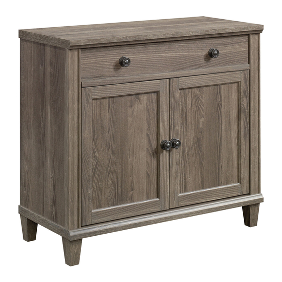
Hammond Collection | Model 423531
Need help? Visit Sauder.com to view video assembly tips or chat with a live rep.
Prefer the phone? Call 1-800-445-1527.
Share your journey!
Here's one for
the books.
NOTE: THIS INSTRUCTION
BOOKLET CONTAINS IMPORTANT
SAFETY INFORMATION.
PLEASE READ AND KEEP FOR
FUTURE REFERENCE.
English pg 1-20
Français pg 21-24
Español pg 25-28
Lot #: 523980
Date Purchased: __________________
12/11/18
Be sure to give us a ring before
making any returns. 1-800-445-1527
Advertisement

Related Manuals for Sauder Hammond 423531


Summary of Contents for Sauder Hammond 423531
- Page 1 NOTE: THIS INSTRUCTION BOOKLET CONTAINS IMPORTANT SAFETY INFORMATION. PLEASE READ AND KEEP FOR Need help? Visit Sauder.com to view video assembly tips or chat with a live rep. FUTURE REFERENCE. Prefer the phone? Call 1-800-445-1527. English pg 1-20 Français pg 21-24 Español pg 25-28...
- Page 2 Table of Contents Assembly Tools Required Part Identifi cation No. 2 Phillips Screwdriver Tip Shown Actual Size Hardware Identifi cation Assembly Steps 5-20 Skip the power trip. Français 21-24 This time. Español 25-28 Safety 29-30 Warranty Page 2 www.sauder.com 423531...
- Page 3 RIGHT DRAWER SIDE (1) BACK (2) RIGHT END (1) LEFT DRAWER SIDE (1) CENTER BACK (1) BOTTOM (1) DRAWER BACK (1) WOOD BLOCK (1) ADJUSTABLE SHELF (1) DRAWER BOTTOM (1) FOOT (4) BRACE (1) DRAWER BRACE (1) 423531 www.sauder.com Page 3...
- Page 4 BLACK 1-3/8" FLAT HEAD SCREW - 4 BLACK 1" MACHINE SCREW - 4 BLACK 5/8" FLAT HEAD SCREW - 30 BLACK 1/2" FLAT HEAD SCREW - 6 BLACK 1/2" PAN HEAD SCREW - 16 BLACK 1" FLAT HEAD SCREW - 2 Page 4 www.sauder.com 423531...
- Page 5 Look for this icon. It means a Step 1 video assembly tip is available at www.sauder.com/services/tips Assemble your unit on a carpeted fl oor or on the empty å carton to avoid scratching your unit or the fl oor. Some assembly Push ten HIDDEN CAMS (3) into the ENDS (B and C) and å...
- Page 6 Push six SMALL HIDDEN CAMS (4) into the DRAWER å SIDES (H and J) and DRAWER BRACE (M). (6 used) Arrow Arrow Arrow Hole The arrow in the HIDDEN CAM must point toward the hole in the edge of the board. Page 6 www.sauder.com 423531...
- Page 7 Meet Part (A). This component has been engineered to be lighter, stronger, faster… well ok. Not technically faster. But defi nitely makes for a sturdier Library Base that’ s easier to assemble and friendlier to the environment. (12 used) 423531 www.sauder.com Page 7...
- Page 8 DRAWER BRACE (M). Fasten the WOOD BLOCK (Q) to the BRACE (F) exactly å as shown. Use two BLACK 1" FLAT HEAD SCREWS (22). BLACK 1" FLAT HEAD SCREW (2 used in this step) Page 8 www.sauder.com 423531...
- Page 9 Step 5 Fasten two HINGES (8) to each DOOR (N). Use eight å BLACK 5/8" FLAT HEAD SCREWS (19). BLACK 5/8" FLAT HEAD SCREW (8 used in this step) 423531 www.sauder.com Page 9...
- Page 10 NOTE: The EXTENSION SLIDES will be used later for the DRAWERS. å Push the black lever up and pull the SLIDE from the RAIL. Open end Use these holes. Open end BLACK 5/8" FLAT HEAD SCREW (6 used in this step) Open end Page 10 www.sauder.com 423531...
- Page 11 BOTTOM. Turn four CAM SCREWS (5) into the exact holes shown in the å BOTTOM (D). BLACK 2-3/4" HEX HEAD SCREW (8 used in this step) (8 used) Part (D). Another sturdier, easier, friendlier component! 423531 www.sauder.com Page 11...
- Page 12 D E N i t h i t h f a c S u r D E N H I D S u r f a c H I D D E N i t h o Page 12 www.sauder.com 423531...
- Page 13 NOTE: Be sure the WOOD DOWELS in the ENDS insert å your drink. into the holes in the BOTTOM. Curved edge F E E i t h f a c S u r 423531 www.sauder.com Page 13...
- Page 14 Fasten the TOP (A) to the ENDS (B and C). Tighten four å HIDDEN CAMS. NOTE: Be sure the WOOD DOWELS in the ENDS insert å into the holes in the TOP. Curved edge i t h f a c S u r Page 14 www.sauder.com 423531...
- Page 15 Next, tape the seams of the BACKS (O and P) together å using the ADHESIVE TAPE (12). NOTE: Two of your BACKS may already be taped together å at the seam. (2 used) Seam BLACK 1/2" PAN HEAD SCREW (16 used in this step) 423531 www.sauder.com Page 15...
- Page 16 DRAWER SIDES (H and J) and DRAWER BACK (K). SIDES (H and J) and DRAWER BRACE (M). Tighten fi ve HIDDEN CAMS. NOTE: Be sure the WOOD DOWEL in the DRAWER å BRACE inserts into the hole in the DRAWER FRONT. Page 16 www.sauder.com 423531...
- Page 17 Fasten the EXTENSION SLIDES (2) to the DRAWER å SIDES (H and J). Use six BLACK 1/2" FLAT HEAD SCREWS (21). Open end Use these holes. Open end Open end BLACK 1/2" FLAT HEAD SCREW (6 used in this step) 423531 www.sauder.com Page 17...
- Page 18 Step 14 Fasten two KNOB SETS (9) to the DRAWER FRONT (G). å Use two BLACK 1" MACHINE SCREWS (18). BLACK 1" MACHINE SCREW (2 used for the KNOB SETS) Page 18 www.sauder.com 423531...
- Page 19 DOORS (N) where they come in contact with the WOOD BLOCK on the BRACE (F). BLACK 5/8" FLAT HEAD SCREW (16 used for the HINGES) BLACK 1" MACHINE SCREW (2 used for the KNOB SETS) 423531 www.sauder.com Page 19...
- Page 20 This completes assembly. Clean with your favorite å furniture polish or a damp cloth. Wipe dry. And to celebrate, why not share your success story? To cover HIDDEN CAMS 40 lbs. 15 lbs. 35 lbs. 50 lbs. (4 used) Page 20 www.sauder.com 423531...
- Page 21 élément et conserver le livret pour future référence. DESSUS ................1 EXCENTRIQUE ESCAMOTABLE ....10 Pour contacter Sauder EXTRÉMITÉ GAUCHE ..........1 PETITE EXCENTRIQUE ESCAMOTABLE ....6 en ce qui concerne cet EXTRÉMITÉ DROITE ..........1 VIS D'EXCENTRIQUE ..........16 élément, faire référence...
- Page 22 REMARQUE : Faire appel à une autre personne pour cette étape. Fixer l’ENTRETOISE (F) aux EXTRÉMITÉS (B et C). Serrer deux EXCENTRIQUES ESCAMOTABLES. REMARQUE : S'assurer de bien insérer les CHEVILLES EN BOIS situées sur l'ENTRETOISE dans les trous dans les EXTRÉMITÉS. Page 22 www.sauder.com 423531...
- Page 23 Ensuite, coller les coutures des ARRIÈRES (O et P) ensemble avec TIROIR (G). Utiliser deux VIS À MÉTAUX 25 mm NOIRES (18). du RUBAN ADHÉSIF (12). REMARQUE : Deux des ARRIÈRES peuvent déjà être collés ensemble à la couture. 423531 www.sauder.com Page 23...
- Page 24 VIS À MÉTAUX 25 mm NOIRES (18). Séparer les TAMPONS de la FICHE AVEC TAMPONS (11) et les coller sur les PORTES (N) aux endroits où celle-ci entre en contact avec le BLOC EN BOIS sur l’ENTRETOISE (F). Page 24 www.sauder.com 423531...
- Page 25 Si EXTREMO IZQUIERDO ..........1 PASADOR DE MADERA GRANDE ....18 necesita ponerse en EXTREMO DERECHO ..........1 PASADOR DE MADERA PEQUEÑO .....2 contacto con Sauder en FONDO .................1 BISAGRA ................4 cuanto a esta unidad, refi érase al número ESTANTE AJUSTABLE ..........1 JUEGO DE PERILLAS ..........4...
- Page 26 NOTA: Necesitar la ayuda de otra persona para este paso. Fije la RIOSTRA (F) a los EXTREMOS (B y C). Apriete dos EXCÉNTRICOS ESCONDIDOS. NOTA: Asegúrese de insertar los PASADORES DE MADERA sujetados a la RIOSTRA en los agujeros de los EXTREMOS. Page 26 www.sauder.com 423531...
- Page 27 CINTA ADHESIVA (12). Fije dos JUEGOS DE PERILLAS (9) a la CARA DE CAJÓN (G). Utilice dos TORNILLOS NEGROS PARA METAL de 25 mm (18). NOTA: Dos de los DORSOS ya pueden estar pegadas en la costura. 423531 www.sauder.com Page 27...
- Page 28 TORNILLOS NEGROS PARA METAL de 25 mm (18). Separe los TOPES de las TARJETAS CON TOPES (11) y aplique los topes sobre las PUERTAS (N) por donde hace contacto con el BLOQUE EN MADERA sobre la RIOSTRA (F). Page 28 www.sauder.com 423531...
- Page 29 Les téléviseurs peuvent être un téléviseur. cet eff et. particulièrement lourds. De plus, le poids et l’emplacement du tube image ont tendance à rendre les téléviseurs instables et enclins à tomber vers l’ a vant. 423531 www.sauder.com Page 29...
- Page 30 Además, el peso y la ubicación del tubo de imagen tienden a causar la inestabilidad de televisores y propensa a volcarse hacia adelante. Page 30 www.sauder.com 423531...
- Page 31 à compter de la date d'achat la première fois et qui sont signalés à Sauder dans les limites de couverture de la contre tout défaut de matériaux ou de fabrication des composantes de mobilier Sauder.
- Page 32 Dear Valued Customer: So, how did it go? Thanks so much for choosing Sauder® furniture. I hope the Set a world record for speed? purchase and assembly process was a positive experience Feeling good about yourself? and you feel good about the furniture you just built. If you Nice.
- Page 33 NOTE: THIS INSTRUCTION BOOKLET CONTAINS IMPORTANT SAFETY INFORMATION. PLEASE READ AND KEEP FOR Need help? Visit Sauder.com to view video assembly tips or chat with a live rep. FUTURE REFERENCE. Prefer the phone? Call 1-800-445-1527. English pg 1-13 Français pg 14-15 Español pg 16-17...
- Page 34 METAL PIN - 8 RESTRAINT KIT - 1 CARD - 2 Z-BRACKET - 2 TAPE - 1 BLACK 1" FLAT HEAD SCREW - 8 BLACK 5/8" FLAT HEAD SCREW - 10 BLACK 1/2" PAN HEAD SCREW - 16 Page 2 www.sauder.com 423532...
- Page 35 Use this part identifi cation to help identify similar parts. TOP (1) RIGHT END (1) LEFT END (1) ADJUSTABLE SHELF (2) TOP BRACE (1) BOTTOM BRACE (1) BACK (2) 423532 www.sauder.com Page 3...
- Page 36 Look for this icon. It means a Step 1 video assembly tip is available at www.sauder.com/services/tips Assemble your unit on a carpeted fl oor or on the empty å carton to avoid scratching your unit or the fl oor. Turn ten CAM SCREWS (2) into the exact holes shown in å...
- Page 37 Push ten HIDDEN CAMS (1) into the ENDS (B and C) å and BRACES (E and F). Arrow Arrow Arrow Arrow Hole The arrow in the HIDDEN CAM must point toward the hole in the edge of the board. 423532 www.sauder.com Page 5...
- Page 38 Insert ten WOOD DOWELS (3) into the short edges of the å ENDS (B and C) and BRACES (E and F). Just think. The sooner you do this, the sooner you do something else. (10 used) Page 6 www.sauder.com 423532...
- Page 39 Fasten the ENDS (B and C) to the BRACES (E and F). å Tighten four HIDDEN CAMS. NOTE: Be sure the WOOD DOWELS in the BRACES insert å into the ENDS. Curved edge Surface with HIDDEN CAMS Edge with WOOD DOWELS 423532 www.sauder.com Page 7...
- Page 40 NOTE: Be sure the WOOD DOWELS in the ENDS insert å into the TOP. Peel APPLIQUES from the APPLIQUE CARDS (5) and å stick them onto each visible HIDDEN CAM. To cover HIDDEN CAMS (10 used) Curved edge Page 8 www.sauder.com 423532...
- Page 41 Fasten the BACKS (G) to the BRACES (E and F). Use sixteen å BLACK 1/2" PAN HEAD SCREWS (11). Next, tape the seams of the BACKS (G) together using the å ADHESIVE TAPE (8). BLACK 1/2" PAN HEAD SCREW (16 used in this step) Groove 423532 www.sauder.com Page 9...
- Page 42 Insert eight METAL PINS (6) into the hole locations of å your choice in the ENDS (B and C). Set the ADJUSTABLE SHELVES (D) onto the METAL PINS. Part (D). Another sturdier, easier, friendlier component! (8 used) Page 10 www.sauder.com 423532...
- Page 43 Fasten the METAL Z-BRACKETS (7) to the top of the base unit. Use six BLACK 1" å FLAT HEAD SCREWS (9). BLACK 5/8" FLAT HEAD SCREW (6 used for the BOTTOM BRACE) BLACK 1" FLAT HEAD SCREW (6 used for the BASE UNIT) 423532 www.sauder.com Page 11...
- Page 44 NOTE: There are no pre-drilled holes in the top of the base unit. å Extra pressure is needed for the SCREWS (9). BLACK 5/8" FLAT HEAD SCREW (4 used for the BOTTOM BRACE) BLACK 1" FLAT HEAD SCREW (2 used for the BASE UNIT) Page 12 www.sauder.com 423532...
- Page 45 And to celebrate, why not share your success story? Use the short screw through the hole in the strap and into the top surface of the TOP (A). Drill this hole into a stud in your wall. No load 25 lbs. 25 lbs. 423532 www.sauder.com Page 13...
- Page 46 QUANTITÉ d’ a chat de cet élément et conserver le livret pour future référence. DESSUS ................1 EXCENTRIQUE ESCAMOTABLE ....10 Pour contacter Sauder EXTRÉMITÉ DROITE ..........1 VIS D'EXCENTRIQUE ..........10 en ce qui concerne cet EXTRÉMITÉ GAUCHE ..........1 CHEVILLE EN BOIS ..........10 élément, faire référence...
- Page 47 ÉTAPE 7 Relever, avec précaution, l'élément dans sa position verticale. Insérer huit GOUPILLES EN MÉTAL (6) dans les trous choisis dans les EXTRÉMITÉS (B et C). Poser les TABLETTES RÉGLABLES (D) sur les GOUPILLES EN MÉTAL. 423532 www.sauder.com Page 15...
- Page 48 EXTREMO DERECHO ..........1 BIELA DE EXCÉNTRICO ........10 necesita ponerse en EXTREMO IZQUIERDO ..........1 PASADOR DE MADERA ........10 contacto con Sauder en ESTANTE AJUSTABLE ..........2 SOPORTE EN L DE METAL .........2 cuanto a esta unidad, refi érase al número RIOSTRA DE PANEL SUPERIOR ......1 TARJETA CON APLICACIONES ......2...
- Page 49 Cuidadosamente ponga la unidad en posición vertical. Inserte ocho ESPIGAS DE METAL (6) dentro de los agujeros al nivel preferido de los EXTREMOS (B y C). Coloque los ESTANTES AJUSTABLES (D) sobre las ESPIGAS DE METAL. 423532 www.sauder.com Page 17...
- Page 50 • Utilice la kit de retención provista para tienden a causar la inestabilidad de mayor estabilidad. televisores y por eso tendrán la tendencia a inclinarse hacia adelante. Page 18 www.sauder.com 423532...
- Page 51 à compter de la date d'achat la première fois et qui sont signalés à Sauder dans les limites de couverture de la contre tout défaut de matériaux ou de fabrication des composantes de mobilier Sauder.
- Page 52 Dear Valued Customer: So, how did it go? Thanks so much for choosing Sauder® furniture. I hope the Set a world record for speed? purchase and assembly process was a positive experience Feeling good about yourself? and you feel good about the furniture you just built. If you Nice.
Need help?
Do you have a question about the Hammond 423531 and is the answer not in the manual?
Questions and answers