Sign In
Upload
Manuals
Brands
Tektronix Manuals
Media Converter
1503C
Tektronix 1503C Manuals
Manuals and User Guides for Tektronix 1503C. We have
1
Tektronix 1503C manual available for free PDF download: User Manual
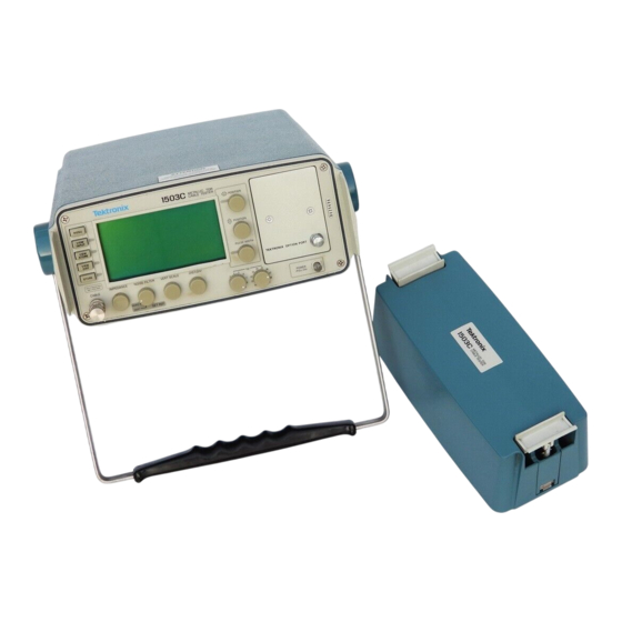
Tektronix 1503C User Manual (128 pages)
Metallic Time-Domain Reflectometer
Brand:
Tektronix
| Category:
Media Converter
| Size: 3 MB
Table of Contents
Table of Contents
5
List of Figures
7
List of Tables
10
General Information
11
Installation and Repacking
12
Contacting Tektronix
14
General Safety Summary
15
Operating Instructions
17
Overview
17
Figure 1-1: Rear Panel Voltage Selector, Fuse, AC Receptacle
17
Figure 1-2: Display Showing Low Battery Indication
19
Preparing to Use the 1503C
20
Figure 1-3: 1503C Front-Panel Controls
20
Display
21
Front-Panel Controls
21
Figure 1-4: Display and Indicators
21
Menu Selections
23
Test Preparations
26
Figure 1-5: Vp Set at .30, Cursor Beyond Reflected Pulse (Setting too Low)
27
Cable Test Procedure
28
Figure 1-6: Vp Set at .99, Cursor Less than Reflected Pulse
28
Figure 1-7: Vp Set at .66, Cursor on Rising Edge of Reflected
28
Figure 1-8: 20-Ft Cable at 5 Ft/DIV
29
Figure 1-9: Short in the Cable
29
Figure 1-10: Open in the Cable
30
Figure 1-11: 455-Ft Cable
30
Figure 1-12: 455-Ft Cable with 20 Ft/DIV, Cursor off Screen
31
Figure 1-13: Return Loss
31
Figure 1-14: Reflection Adjusted to One Division in Height
32
Figure 1-15: Display with VIEW INPUT Turned off
33
Figure 1-16: Display of a Stored Waveform
34
Figure 1-17: Display of a Stored Waveform and Current Waveform
34
Figure 1-18: Display of a Stored Waveform, Current Waveform, and Difference Waveform
35
Figure 1-19: Waveform Moved to Top Half of Display
35
Figure 1-20: Current Waveform Centered, Stored
36
Figure 1-21: Current Waveform Center, Stored Waveform
36
Figure 1-22: Waveform of Three-Foot Lead-In Cable
37
Figure 1-23: Cursor Moved to End of Three-Foot Lead-In Cable
38
Figure 1-24: Cursor Moved to End of Three-Foot Lead-In Cable
38
Figure 1-25: Cursor Moved to 0.00 Ft
39
Figure 1-26: Incident Pulse at Four Divisions, FILTER at Desired Setting
39
Additional Features (Menu Selected)
40
Figure 1-27: Waveform Viewed in Normal Operation
40
Figure 1-28: Waveform Showing Intermittent Short
41
Figure 1-29: Waveform Display with no Outgoing Pulses
41
Operator Tutorial
43
What Is the Tektronix 1503C
43
How Does It Do It
43
You, the Operator
43
Menus and Help
43
Getting Started
44
Pulse (Set Correctly)
45
The Waveform up Close
46
A Longer Cable
48
Noise
51
Set Ref ( Mode)
53
View Input
56
STORE and VIEW STORE
57
View Diff
59
Menu-Accessed Functions
60
TDR Questions and Answers
65
Options and Accessories
67
Option 04: YT-1 Chart Recorder
67
Option 05: Metric Default
67
Option 06: Ethernet
67
Option 07: YT-1S Chart Recorder
83
Option 08: Token Ring Adapter
83
Option 09: Universal Service Ordering Code
84
Option 10: Token Ring Interface
84
Power Cord Options
84
Accessories
85
Appendix A: Specifications
87
Electrical Characteristics
87
Environmental Characteristics
89
Certifications and Compliances
90
Physical Characteristics
91
Appendix B: Operator Performance Checks
93
Appendix C: Operator Troubleshooting
105
Error Messages
107
Appendix D: Application Note
109
Glossary
117
Index
123
Advertisement
Advertisement
Related Products
Tektronix 1503
Tektronix 1502
Tektronix MIL-STD 1553
Tektronix 1502C
Tektronix 1500-SERIES
Tektronix 1502B
Tektronix 1503B
Tektronix 153
Tektronix 1501
tektronix 1730 Series
Tektronix Categories
Test Equipment
Measuring Instruments
Amplifier
Portable Generator
Printer
More Tektronix Manuals
Login
Sign In
OR
Sign in with Facebook
Sign in with Google
Upload manual
Upload from disk
Upload from URL