
Related Manuals for Casio DR-120LB


Summary of Contents for Casio DR-120LB
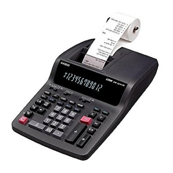
- Page 1 (without price) DR-120LB (ZX-517C) DL-200L (ZX-517A) DL-210L (ZX-517B) DR-320B (ZX-517D) JULY 1996 DR-120LB DR-320B...
-
Page 2: Table Of Contents
CONTENTS SPECIFICATIONS ......................1 BLOCK DIAGRAM ......................1 CPU (MN15418YCY) PIN FUNCTION ................2 DIAGNOSTIC ........................ 3 TROUBLESHOOTING ....................4 DISASSEMBLY VIEW ....................5 SCHEMATIC DIAGRAMS ..................... 6 PARTS LIST ........................ 10... -
Page 3: Specifications
1. SPECIFICATIONS 4 basic arithmetic operations (+, –, ×, ÷), constants for ×/÷, sub-total/ Functions: total/grand total, item counting, ADD mode calculations, repeat calcu- lations, memory calculation, percentage calculations and various kinds of practical calculations. Decimal point: Full floating, and fixed (0, 1, 2, 3, 4, or 6) with round off, round-up cut- off. -
Page 4: Cpu (Mn15418Ycy) Pin Function
3. CPU (MN158418YCY) PIN FUNCTION Pin No. Signal I / O Function 1 ~ 7, 64 P00 ~ P13 Common signal for keyboard 8 ~ 12 P20 ~ P22, P32, P33 Key signal from keyboard Timing pulse signal from printer DEBIN Reset pulse (Not used) IRQCNT... -
Page 5: Diagnostic
4. DIAGNOSTICS STEP MODE SWITCHES OPERATION DISPLAY PRINT NOTE 1 0 00 1000. 8 – ÷ 9 % ◊/# The character with "[ ]" -888.888888888 -888.88888888 will be printed by red PRINT ink. 1 2 3 4 ÷ PRINT 1234. 7 6 5 + PRINT 1.61307189542... -
Page 6: Troubleshooting
5. TROUBLESHOOTING Trouble Cause Checkpoint Note 1) Does not work • Defective power transformer Secondary voltage VDD, VSS, VM, VF1, and of transformer VF2 are OK? at all. • Defective LSI Waveforms of each VF1, VF2 2) No display. • No voltage at VF1, VF2 •... -
Page 7: Disassembly View
6. DISASSEMBLY VIEW... -
Page 8: Schematic Diagrams
7. SCHEMATIC DIAGRAMS 7-1. Main PCB POWER CORD 286S0255-1 (USA, CANADA) EP-483-E03 (EUROPE, SAUDI) SP-852-J03 (AUSTRALIA) SE-225-1D1U (USA, 120 V) SE-225-1D1J (JAPAN, CANADA, 100/120 V) SE-225-1D2 (EUROPE, 230/240 V) — 6 —... - Page 9 7-2. Keyboard PCB — 7 —...
- Page 10 7-3. Slide Switch Board PCB — 8 —...
- Page 11 7-4. Printer Pin Arrangement Diagram Connection Pin No. Pin No. Connection RD terminal Character selective magnet column No.1 (Not used) Character selective magnet column No.1 Notes: 1. Column numbers match the physical arrange- ment of the columns on the print wheels. 2.
-
Page 12: Parts List
1S2472-T-77-T D13, 14 2301 0101 Diode 1S2473-T-77-T DIG1 3301 0217 Display tube 13-BT-144G The following elecrical parts will be not supplied from CASIO. 2845 3241 Semiconductive capacitor DD308-959F104Z50 2803 9198 Electrolytic capacitor RE2-50V331M-T2 2803 8199 Electrolytic capacitor RE2-25V222M-T50 2813 3178 Semiconductive capacitor... - Page 13 6419 5010 Roll arm L- L227A P340024-1 The Parts prices will be informed separately by Parts Price List. Notes: N – New parts A: DR-120LB Q – Quantity used per unit B: DR-320B R – Rank C: DL-210L D: DL-200L...
- Page 14 MA0900461A...
Need help?
Do you have a question about the DR-120LB and is the answer not in the manual?
Questions and answers