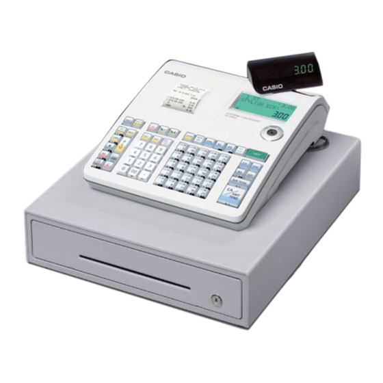
1. SPECIFICATIONS 1-1. Electrical specifications • Power consumption 120 V 230 V 240 V In operation Max. 0.4 A 0.26 A 0.26 A Display off Max. 0.05 A 0.04 A 0.04 A • Memory protection Back-up battery Two new size AA alkaline batteries Back-up period 1 year (25 °C) Battery life...
Page 5
1-5. Option List DEVICE NAME MODEL NOTE Applicable Roll paper TRP-5880T Common Waterproof cover WT-89 SE-S300/S2000, TE-900/1500, PCR series Waterproof cover WT-90 SE-C300/C2000, TK-950/1550 Sheet cover WT-91 SE-C300/C2000, TK-950/1550 PC cable PRL-CB-2 Common External memory RAC-12B 4MB (Thermal pop) Common...
Use the following procedure to initialize the cash register and clear all transaction data and program data from its memory. 1. Insert the mode key marked “PGM” into the mode switch. 2. Turn the mode switch to the OFF position. 3. SE-S300/SE-C300: While holding down the key, turn the mode switch to the PGM position. FEED...
Should it happens, you can use the following procedure to clear the lock up without losing any data. 1. Power off the register. 2. Insert the PGM key in the mode switch. 3. SE-S300/SE-C300: Press down and hold , and turn the mode switch to PGM mode.
Page 8
RS232C cross cable which is using CV10 Memory pack RAC-12B RAC_TOOL software IPL data file *Please contact CASIO sales division to get the above materials. PC with RS232C COM port Windows 2000 / XP / Vista 2. System configuration RS232C Cross Cable...
Page 9
4) Plug in the power cord of ECR to the AC outlet and start up the diag software. (See Page 18) 5) Make double-click RAC_TOOL.exe to run the software. * RAC_TOOL.exe, FILE969.HAD, and LogoConv.dll (3 files) must be stored at same folder. 6) Select the appropriate COM port according to your configuration.
Page 10
12) Enter your INIT code and press "Sub Total" key, then the information will be printed. * INIT code is as follows; Model Name INIT Code SE-C300 / SE-C2000 17200 SE-S2000 13040 SE-S300 12540 TE-1500 23040 TE-900 22540 TK-950 / TK-1550 27200...
3. DISASSEMBLY ■ Removing the upper case block 1. Remove the Printer cover. 2. Remove two Roll paper and theTake-up reel. Take-up reel Printer cover 3. Remove the battery cover and disengage the battery. 4. Remove 3 screws. Screw Screws —...
Page 12
5. Lift the upper case block and then remove 3 FPCs. Hooks Hooks Hooks FPC (KEY) FPC (Pop-up displasy) Assembling Point: Be sure to insert the FPC securely by holding it with both hands or, if holding it with one hand, holding by its center.
Page 13
■ Upper case block disassembly (KEY BOARD ASS'Y, MODE SW ASS'Y, POP-UP DISPLAY BLOCK) 1. Remove the FPC. 2. Remove 8 screws and then the KEY BOARD ASS’Y. Screws Assembling Point: Secure the FPC (Mode key, Pop-up Display). 3. Remove 15 screws and then disassemble the KEY BOARD ASS'Y. Screws —...
Page 14
4. Remove the screw and then the MODE SW ASS’Y. Screw 5. Remove the hook and then remove the STROBE ASSY Hooks 6. Remove the hook and then remove the STROBE ASSY. 7. Remove two FPCs and then remove the Rear Display Board. —...
Page 15
■ Lower case block disassembly (Printer unit, MAIN PCB, LCD unit, E292-COM PCB) 1. Remove 4 screws. 2. Remove 2 FPCs and then 2 Printer units. Screws FPCs 3. Remove the FPC and 5 connectors. Drawer Motor Battery Power COM Port Assembling Point: Run the power cable and the motor wires through the groove on the case.
Page 16
4. Remove 3 screws. Screws 5. Loosen the screw and change the orientation of the plate. 6. Remove the main PCB. 7. Remove a screw. Screw — 14 —...
Page 17
8. Remove the hook and then remove the LCD ASSY. 9. Remove 2 screws and then the LCD and E292LCD-E2 PCB. Screws 10. Unsolder to remove 3 lead wires. 11. Remove the FPC and then the E292LCD-E2 PCB. Lead wires —...
Page 18
12. Remove 2 screws and then the Lower case unit ans AC Adaptor. Lower case unit Screws Drawer AC Adaptor 13. Remove 3 screws and then the Lower case unit ans AC Adaptor. Screws 14. Remove 2 screws and then the Motor assy. Motor assy Screws 15.
Thermal PRN UNIT LCD UNIT Receipt Journal Winder Motor PWB:E283-E22 Feed Motor Feed Motor MODE KEY PWB:E292LCD-E2-1 PWB:E274-E3 SE-S300/SE-S2000/TE-900/ TE-1500/PCR series (STROKE KEY) SE-C300/SE-C2000/ TK-950/TK-1550 (COMBINATION KEY) SRAM FROM 4Mbit 32Mbit POWER SUPPLY UNIT AC Adaptor S01224A PWB : E292-COM...
5. DIAGNOSTIC OPERATION 5-1. To start the diagnostic program 1. First, be sure that MODE KEY is “OFF”. While holding down the “JFEED” button, turn MODE KEY to “PGM”. When the “JFEED” button is released, the main display indicates as illustrated below. INIT TOTAL CHANGE AMOUNT...
Page 21
5-3. Displaying the status of the device [Function] Changing to status mode or pressing the “C” key when the device is in the command input wait state during test program startup displays the device status. [DISPLAY] The figure below shows the relative display positions for the status information. DIAG TOTAL CHANGE AMOUNT...
Page 22
5-4. Check item The following test can be checked in the diagnostic test. No Device to be checked Operation Note Page BATCH TEST 1 Test Device : RAM READ/WRITE test, Watch, buzzer test and drawer open test are performed continuously. BATCH TEST 2 Test Device : Display test and LCD...
Page 23
5-5. Operation of each test [ 1 ] BATCH TEST 1 [Function] RAM READ/WRITE test, Watch, buzzer test and drawer open test are performed continuously. [Operation] Operation : 1 SUB TOTAL The following tests are performed automatically. (1) RAM test: WRITE/READ area test.
Page 24
[ 3 ] RAM WRITE/READ TEST [Function] Data on the RAM is written, and tests are performed to check if the data has been written properly. The data to be written should be a one-byte data, which is the sum of the fourth, the third, and the second digits from the last of the address.
Page 25
[ 5 ] FLASH ROM CLEAR TEST [Function] After this test, be sure to perform [6] FLASH ROM WRITE/READ test before conducting other tests. If other tests are performed without having conducted FLASH ROM WRITE/READ test and the program is damaged, proper operation cannot be guaranteed. Please perform IPL again. [Operation] Operation : n SUB TOTAL...
Page 26
[ 7 ] FLASH ROM CLEAR & WRITE/READ TEST [Function] After CLEAR function clears the memory, WRITE test is performed. [Operation] Operation : n SUB TOTAL 0 = One time check (can be omitted) not 0 = Continuous check (To stop the test, press “C” key) [Display] A counter is displayed in the 7 segments to indicate that RAM check is in progress.
Page 27
[ 9 ] DISPLAY TEST [Function] The test of LCD/7 segment display and transaction display is performed as shown below. Command input Pattern 1 Pattern 2 Press Any key Press Any key Pattern 1 Pattern 2 ABCDEFGHIJKLMOP QRSTUVWXYZabcdef TOTAL CHANGE TOTAL CHANGE AMOUNT AMOUNT...
Page 28
[ 10 ] DISPLAY TEST (REPEAT) [Function] The test of LCD/7 segment display and transaction display is performed as shown below. Pattern 1 Pattern 2 Pattern 3 TOTAL CHANGE TOTAL CHANGE TOTAL CHANGE AMOUNT AMOUNT AMOUNT [Operation] Operation : 5 SUB TOTAL To stop the test, press “C”...
Page 29
[ 12 ] LCD BACKLIGHT TEST [Function] LCD Backlight is turned ON/OFF. [Operation] Operation : c SUB TOTAL 0 = Press any button to turn “OFF” -> “ON” 1 = Backlight OFF 2 = Backlight ON [Print] D I S P 1 2 1 D I S P L I G H T...
Page 30
[ 14 ] LCD CONTRAST ADJUSTMENT TEST [Function] Adjusts the LCD contrast and writes the adjustment to the FLASH ROM. Up to 16 adjustments can be written to the FLASH ROM. If more than 16 adjustments are written, an error occurs. The contrast value when adjustment begins is the value written during the previous adjustment ("22"...
Page 31
[ 15 ] LCD BIT MAP TEST [Function] Performs an LCD display pattern test. Command input Pattern 1 Pattern 4 Press Any key Press Any key Pattern 1 Pattern 2 Pattern 3 Pattern 4 TOTAL CHANGE TOTAL CHANGE TOTAL CHANGE TOTAL CHANGE AMOUNT AMOUNT...
Page 32
[ 16 ] INTERNAL PRINTER CHARACTER PRINT TEST [FUNCTION] This test will check the characters in the receipt/journal of the internal printer. [Operation] Operation : a SUB TOTAL 0 = normal print out 1 = reduced size print out 0 = prints character’ B’ 1 = prints all characters 0 = One time check not 0 = Continuous check (To stop the test, press “C”...
Page 33
[ 17 ] INTERNAL PRINTER GRAPHIC PATTERN PRINT TEST [FUNCTION] This test will check the graphic patterns in the receipt/journal of the internal printer. The graphic patterns and the print images are as follows; Graphic pattern 1 Graphic pattern 2 Graphic pattern 1 Graphic pattern 2 : repeat (for 28 Dot line )
Page 34
[ 18 ] INTERNAL PRINTER DOT RATE TEST [FUNCTION] This test will check the printing of the receipt/journal according to the following specifications. The printing specification is reflected in 1/2 line and the only specified number of dot lines are printed in all dots from the 1 dot line.
Page 35
[ 19 ] INTERNAL PRINTER PRINT TEST [FUNCTION] Print out is performed on the internal printer receipt/journal in the following format. This test is performed once. The number of the tests to be performed cannot be changed. [Operation] Operation : 4 SUB TOTAL [Print] P R T...
Page 36
[ 21 ] RS232C PORT BATCH TEST [Function] This is the RS232C port batch test. When performing this test, fix loop back connectors to all COM ports. By the setting below, the loop back batch test is performed once from COM1 through COM2. [Operation] Operation : 4 SUB TOTAL...
Page 37
[ 22 ] TIME SETTING [ 23 ] TIME DISPLAY [Function] This sets the time and date. When setting the time, the time and date will be displayed without inputting the fixed value. [Operation] (1) Date and time setting Operation : h SUB TOTAL hour mm: minutes...
Page 38
[ 24 ] DRAWER OPEN TEST [Function] This test checks whether the drawer opens or not.. [Operation] Operation : n SUB TOTAL 0 = One time check not 0 = Continuous check (To stop the test, press “C” key) [Print] D R W D R W E N D...
Page 39
Operation : 9 SUB TOTAL KEY CODE To stop the test, press “C” ke 11:STROKE KEY 10:COMBI KEY [Location of the key code] STROKE KEY (SE-S300/SE-S2000) TOTAL CHANGE AMOUNT 089 082 076 073 070 067 060 053 046 039 032...
Page 40
The test determines the result between OK and NG by comparing the fixed data and the read data. * The fixed barcode is as follows. [Operation] SE-S2000/SE-C2000: COM2 SE-S300/SE-C300: COM1 Operation : 9 CA/AMT TEND To stop the test, press “C” key...
6. ERROR CODE LIST This section describes what to do when you have problems with operation. When an error occurs Errors are indicated by an error codes. When this happens, you can usually find out what the problem is as illustrated below. Press and check the appropriate section of this manual for the operation you want to perform.
Page 42
Error Message Meaning Action code E040 Issue guest receipt Attempt to register a new transaction Issue a guest receipt. without issuing a guest receipt. E046 REG buffer full Registration buffer full. Finalize the transaction. E049 CHECK memory full Check tracking index memory full. Finalize and close the check number currently used.
8. CIRCUIT DIAGRAMS SE series SE-S300/SE-S2000/SE-C300/SE-C2000 TE series / TK series TE-900/TE-1500/TK-950/TK-1550 PCR series PCR-T48S/PCR-T470/PCR-T480/PCR-T470L/PCR-T480L PCR-T220S/PCR-T2100/PCR-T2200/PCR-T2100L/PCR-T2200L (EX-292/EX-293/EX-592/EX-593) 1. MAIN PCB CIRCUIT 1-1. MAIN PCB CIRCUIT 1/5 (PW,PWD,COM) ................44 1-2. MAIN PCB CIRCUIT 2/5 (CPU) ..................45 1-3. MAIN PCB CIRCUIT 3/5 (ROM,RAM,SIO) ................46 1-2.
Page 46
SE-S300 and SE-C300: not used SE-S300: not used Model Board No. Name Drawing No. CASIO COMPUTER CO.,LTD. SE-S300/S2000/C300/C2000 E292-1 MAIN BOARD 1/5 (PW, PWD, COM) RJE502513D201 — 44 —...
Page 47
SW1, R234, C112: not used Model Board No. Name Drawing No. CASIO COMPUTER CO.,LTD. SE-S300/S2000/C300/C2000 E292-1 MAIN BOARD 2/5 (CPU) RJE502513D201 — 45 —...
Page 48
R233: not used Model Board No. Name Drawing No. CASIO COMPUTER CO.,LTD. SE-S300/S2000/C300/C2000 E292-1 MAIN BOARD 3/5 (ROM, RAM, SIO) RJE502513D201 — 46 —...
Page 49
Model Board No. Name Drawing No. CASIO COMPUTER CO.,LTD. SE-S300/S2000/C300/C2000 E292-1 MAIN BOARD 4/5 (LCD, KEY, LED) RJE502513D201 — 47 —...
Page 50
R173:SE-S300 not used SE-S300: not used SE-S300: not used R219,220,221,222:SE-S2000 not used SE-S300: not used SE-S300/C300 only SE-S2000/C2000 only SE-S2000: not used SE-S300: not used R223,224,225,226,227,228:SE-S2000 not used IC22,C75,R184:SE-S300 not used SE-S300: not used Model Board No. Name Drawing No.
Page 51
SE-S2000/SE-C2000 only Model Board No. Name Drawing No. CASIO COMPUTER CO.,LTD. SE-S300/S2000/C300/C2000 E283-E22 CON BOARD — 49 —...
2. As for spare parts order and supply, refer to the “GUIDEBOOK for Spare Parts Supply”, published separately. 3. The numbers in item column corespond to the same numbers in drawing. 4. CASIO does not supply the spare parts without parts code. 5. Remarks...