
Related Manuals for LEYBOLD THERMOVAC TTR 91 R


Summary of Contents for LEYBOLD THERMOVAC TTR 91 R
- Page 1 THERMOVAC Transmitter TTR 91 R Operating Manual 300710168_002_C1 Part Number: 230049V01 300710168_002_C1 - 01/2018 - © Leybold...
-
Page 2: Table Of Contents
Bakeout Maintenance Atmosphere and vacuum adjustment Atmosphere adjustment Vacuum adjustment Remote adjustment Adjustment for new tube Replace the gauge tube FAQ (Frequently Asked Questions) Storage and disposal Declaration of Contamination EU Declaration of Conformity 300710168_002_C1 - 01/2018 - © Leybold... -
Page 3: Safety Information
Safety Precautions: Critical Corrosive Environments. The transmitter is not intended for use in corrosive environments If you need further support please contact Leybold. Caution Do not use the TTR 91 R to measure the pressure of explosive or flammable gasses or mixtures. -
Page 4: Liability And Warranty
Always wear clean, lint-free gloves and use clean tools when working in this area. Liability and Warranty Leybold assumes no liability and the warranty becomes null and void if the end-user or third parties disregard the information in this document ... -
Page 5: Unpacking
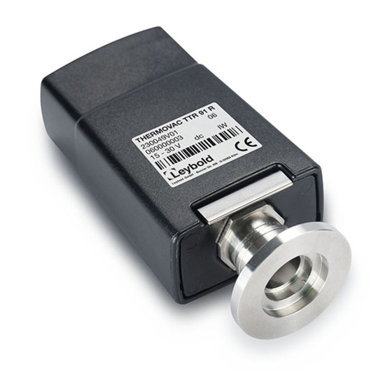
1 pcs. German short form manual (P/N: 300710168_001_C0) 1 pcs. English short form manual (P/N: 300710168_002_C0) If any items are missing, please contact Leybold. Description The TTR 91 R is a Pirani gauge which measures vacuum pressures in the range 5×10 mbar to 1000 mbar. -
Page 6: Technical Data
Min load impedance 10 kΩ Max output current 1 mA Set-point Adjustment range 1.4 to 10.0 V Hysteresis 500 mV Max external load rating 30 V d.c., 100 mA Gauge identification resistance 27 kΩ 300710168_002_C1 - 01/2018 - © Leybold... - Page 7 Dimensions (mm) 300710168_002_C1 - 01/2018 - © Leybold...
-
Page 8: Accessories And Replacement Part Numbers
Centering Ring with fine filter DN 16 ISO-KF 88396 Calibration service A calibration service is available for all Leybold gauges. Calibration is by comparison with reference gauges, traceable to National Standards. Contact Leybold for details. 300710168_002_C1 - 01/2018 - © Leybold... -
Page 9: Installation (Mechanical)
To connect the TTR91R to your vacuum system use an 'O' ring / centring-ring to connect a TTR91R with a DN16 ISO-KF flange to a similar flange on the vacuum system. To connect to a Leybold controller use a shielded cable which is terminated in suitable RJ45 connectors. These cables are available from Leybold (Cable Type A). -
Page 10: Recommended Electrical Connections
When using the TTR 91 R in an electrically noisy environment you should ensure that your measuring equipment is adequately immune to interference. All Leybold controllers have adequate immunity. The set-point output on pin 6 is an active low open-collector transistor suitable for driving a d.c. relay or control logic. -
Page 11: Operation
If the gauge is connected to a Leybold controller the display will indicate the measured pressure. The TTR 91 R provides a voltage output which is a function of pressure. The output voltage scales with 1.296V dc / decade. - Page 12 3.00E+00 6.757 5.00E+02 9.614 2.00E-02 3.958 4.00E+00 6.917 6.00E+02 9.716 3.00E-02 4.185 5.00E+00 7.042 7.00E+02 9.802 4.00E-02 4.345 6.00E+00 7.144 8.00E+02 9.876 5.00E-02 4.470 7.00E+00 7.230 9.00E+02 9.942 6.00E-02 4.572 8.00E+00 7.304 1.00E+03 10.000 300710168_002_C1 - 01/2018 - © Leybold...
-
Page 13: Gas Dependency
For pressures below 1 mbar a simple calibration factor can be used to correct for different gas types. Gas Calibration Factors (GCFs) for common gases are shown below. True pressure = GCF x indicated pressure Gas calibration factors below 1 mbar 300710168_002_C1 - 01/2018 - © Leybold... -
Page 14: Set-Point Adjustment
Note: If you use a Leybold Controller the TTR 91 R set-point is not used. To read the pressure at which the set-point output turns on, push the "S/P" button with an appropriate tool. The signal output of the gauge will change to indicate the set-point threshold for three seconds after which the output will return to normal. -
Page 15: Error Monitoring
The tube of the TTR 91 R can be baked to 150°C, but the electronics housing must be removed. Referring to the figure in section 6.7, remove the electronics housing. When baking the tube on your system, do not exceed 150°C. Always allow the tube to cool before refitting the electronics housing. 300710168_002_C1 - 01/2018 - © Leybold... -
Page 16: Maintenance
2. Press the 'CAL' button. The status LED turn amber and the gauge will automatically adjust to read atmospheric pressure. Do not hold the ‘CAL’ button down for longer than 5 seconds (see ‘Adjustment for new tube’ below). 300710168_002_C1 - 01/2018 - © Leybold... -
Page 17: Vacuum Adjustment
This may take several seconds. 3. Allow the gauge to operate at atmospheric pressure for at least 10 minutes and then repeat step 2. 4. It is now necessary to perform the vacuum adjustment as described above. 300710168_002_C1 - 01/2018 - © Leybold... -
Page 18: Replace The Gauge Tube
Whenever a new tube is fitted it is necessary to adjust the gauge to match the new tube. Refer to ‘Adjustment for new tube’ above. Replacement of gauge tube Electronic housing Retaining clip Gauge tube 300710168_002_C1 - 01/2018 - © Leybold... -
Page 19: Faq (Frequently Asked Questions)
For the benefit of the environment, at the end of life of the transmitter, it should not be disposed in the normal unsorted waste stream. It should be deposited at an appropriate collection point or facility to enable recovery or recycling. 300710168_002_C1 - 01/2018 - © Leybold... -
Page 20: Declaration Of Contamination
All dispatch instructions laid down in the manual must be followed e.g.: • Drain all service fluids • Remove filter elements • Seal all openings airtight • Pack / handle appropriately • Attach the declaration of contamination outside of the packaging 300710168_002_C1 - 01/2018 - © Leybold... - Page 21 300710168_002_C1 - 01/2018 - © Leybold...
-
Page 22: Eu Declaration Of Conformity
EN 50581:2012 Technical documentation for the assessment of electrical and electronic products with respect to the restriction of hazardous substances Documentation officer: Leybold GmbH, Bonner Straße 498, D-50968 Köln Herbert Etges T: +49(0)221 347 0 F: +49(0)221 347 1250 documentation@leybold.com... - Page 23 7(c) I Electrical and electronic components containing lead in a glass or ceramic other than dielectric ceramic in capacitors, e.g. piezoelectronic devices, or in a glass or ceramic matrix compound 15 Lead in solders to complete a viable electrical connection between semiconductor die and carrier within integrated circuit flip chip packages 300710168_002_C1 - 01/2018 - © Leybold...
- Page 24 300710168_002_C1 - 01/2018 - © Leybold...
Need help?
Do you have a question about the THERMOVAC TTR 91 R and is the answer not in the manual?
Questions and answers