
Related Manuals for LEYBOLD IONIVAC Series


Summary of Contents for LEYBOLD IONIVAC Series
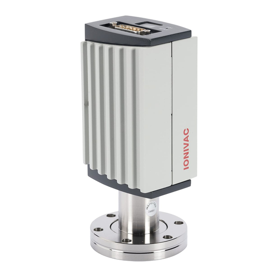
- Page 1 IONIVAC ITR 90 ITR 90 P Operating Manual GA09420_002_C0 Part Numbers 120 90 120 91 120 92 120 94 230 030 230 031...
-
Page 2: Product Identification
They must not be used for measuring flammable or combustible gases in mixtures containing oxidants (e.g. atmospheric oxygen) within the explosion range. The transmitters can be operated in connection with a Leybold controller or with other control devices. GA09420_002_C0 – (2016-10) –... -
Page 3: Functional Principle
The hot cathode is switched on by the Pirani measurement system only below the switching threshold of 2.4×10 mbar (to prevent filament burn-out). It is switched off when the pressure exceeds 3.2×10 mbar. GA09420_002_C0 – (2016-10) – Leybold... -
Page 4: Table Of Contents
3.1.1 Making the Flange Connection 3.1.2 Removing and Installing the Electronics Unit 3.1.3 Using the Optional Baffle 3.2 Electrical Connection 3.2.1 Use With Leybold Transmitter Controllers 3.2.2 Use With Other Controllers 3.2.3 Using the Optional Power Supply (With RS232C Line) 4 Operation 4.1 Measuring Principle, Measuring Behavior... -
Page 5: Safety
Skilled personnel All work described in this document may only be carried out by persons who have suitable technical training and the necessary experience or who have been instructed by the end-user of the product. GA09420_002_C0 – (2016-10) – Leybold... -
Page 6: General Safety Instructions
Communicate the safety instructions to all other users. Liability and Warranty Leybold assumes no liability and the warranty becomes null and void if the end- user or third parties • disregard the information in this document •... -
Page 7: Technical Data
Display (120 91 and 120 94) Display panel LCD matrix, 32×16 pixels, with background illumination Dimensions 16.0 mm × 11.2 mm Pressure units (pressure p) mbar (default), Torr, Pa (selecting the pressure unit → 29) GA09420_002_C0 – (2016-10) – Leybold... - Page 8 The transmitter must only be connected to power supplies, instru- ments or control devices that conform to the requirements of a grounded extra-low voltage (PELV). The connection to the transmitter has to be fused (Leybold controllers fulfill these requirements). Operating voltage at the +24 VDC (20 … 28 VDC) IONIVAC ITR 90 ripple max.
- Page 9 00 … 7D (0 … 125 Profibus connection D-Sub, 9-pin, female Cable Shielded, special Profibus cable (→ 22 and [4]) Cable length, system wiring According to Profibus specifications (→ [4], [5]) GA09420_002_C0 – (2016-10) – Leybold...
- Page 10 0 … 50 °C Bakeout +150 °C (without electronics unit) Relative humidity (year's mean / during 60 days) ≤65 / 85% (no condensation) indoors only altitude up to 2000 m NN Type of protection IP 30 GA09420_002_C0 – (2016-10) – Leybold...
- Page 11 Technical Data Dimensions [mm] Part numbers Part numbers 120 90 120 92 120 91 120 94 230 030 230 031 4-40UNC 2B 4-40UNC 2B DN 25 ISO-KF DN 40 CF-R GA09420_002_C0 – (2016-10) – Leybold...
-
Page 12: Installation
The sensor can be baked at up to 150 °C. At temperatures exceeding 50 °C, the electronics unit has to be removed (→ 14) or an extension (Option → 43) has to be installed. GA09420_002_C0 – (2016-10) – Leybold... -
Page 13: Making The Flange Connection
Installation 3.1.1 Making the Flange Connection Procedure It is recommended not to apply any vacuum grease. The protective lid will be needed for maintenance. GA09420_002_C0 – (2016-10) – Leybold... -
Page 14: Removing And Installing The Electronics Unit
Remove the electronics unit without twisting it. Removal of the electronics unit is completed. Installing the electronics unit Place the electronics unit on the sensor (3) (be careful to correctly align the pins and notch (4)). GA09420_002_C0 – (2016-10) – Leybold... -
Page 15: Using The Optional Baffle
Always wear clean, lint-free gloves and use clean tools when working in this area. Required tools / material • Baffle (→ 43) • Pointed tweezers • Pin (e.g. pencil) • Screwdriver No 1 Procedure Carefully remove the grid with tweezers. GA09420_002_C0 – (2016-10) – Leybold... - Page 16 Using a pin, press the baffle down in the center until it catches. The baffle is now installed (Installation of the transmitter → 12). Deinstallation Carefully remove the baffle with the screwdriver. GA09420_002_C0 – (2016-10) – Leybold...
-
Page 17: Electrical Connection
Installation Electrical Connection 3.2.1 Use With Leybold Transmitter Controllers See Leybold sales literature and data sources for controllers and our range of sensor cables on our internet home page (→ [6]). Caution Caution: data transmission errors If the transmitter is operated with the RS232C interface and a fieldbus interface at the same time, data transmission errors may occur. -
Page 18: Use With Other Controllers
(→ 8). Procedure Open the cable connector (D-Sub, 15-pin, female). Prepare the cable and solder/crimp it to the connector as indicated in the diagram of the transmitter used: GA09420_002_C0 – (2016-10) – Leybold... - Page 19 (Pin 2) and signal common (Pin 12) is recommended. Reassemble the cable connector. On the other cable end, terminate the cable according to the requirements of the transmitter controller you are using. GA09420_002_C0 – (2016-10) – Leybold...
- Page 20 The transmitter can now be operated via analog and RS232C interface. Sensor cable connection ITR 90 P ITR 90 P SP A SP B SP A SP B RS232 Degas Degas 1.25 AT Measuring signal Identification GA09420_002_C0 – (2016-10) – Leybold...
- Page 21 Connect the other end of the sensor cable to the connector of the instru- ment or transmitter controller you are using. The transmitter can now be operated via analog and RS232C interface. GA09420_002_C0 – (2016-10) – Leybold...
- Page 22 Only to be connected if an optical link module is used. Only required as line termination for devices at both ends of bus cable (→ [4]). Plug the Profibus (and sensor) cable connector into the transmitter. GA09420_002_C0 – (2016-10) – Leybold...
-
Page 23: Using The Optional Power Supply (With Rs232C Line)
RS232C connection D-Sub, 9-pin, female Cable 5 m, black, 3 conductors, shielded Wiring diagram RS232C D-Sub, 9 pins ITR 90 D-Sub, 15 pins +24 V Mains 90 ... 250 VAC 50 ... 60 Hz GA09420_002_C0 – (2016-10) – Leybold... - Page 24 Connect the RS232C line to the instrument or control device and lock the connector with the screws. Connect the power supply to the mains. Turn the power supply on. The transmitter can now be operated via RS232C interface (→ 29). GA09420_002_C0 – (2016-10) – Leybold...
-
Page 25: Operation
At the switching threshold, the ITR 90 can temporarily (<2 s) deviate from the specified accuracy. – – 200V (Degas 250V) Diagram of the BA measuring system hot cathode (filament) ion collector EC anode (electron collector) GA09420_002_C0 – (2016-10) – Leybold... - Page 26 The Pirani measurement value is output. Gas type dependence The output signal is gas type dependent. The characteristic curves are accurate for dry air, N and O . They can be mathematically converted for other gases (→ Appendix B). GA09420_002_C0 – (2016-10) – Leybold...
-
Page 27: Operational Principle Of The Transmitter
(+24 V) to OFF (0 V), to then start degas again with a new ON (+24 V) command. It is recommended that the degas signal be set to OFF again by the system control after 3 minutes of degassing, to achieve an unambiguous operating status. GA09420_002_C0 – (2016-10) – Leybold... -
Page 28: Display
(green background illumination) Pirani sensor error (red background illumination) BA sensor error (red background illumination) Internal data connection failure (red background illumination) What to do in case of problems → 39. GA09420_002_C0 – (2016-10) – Leybold... -
Page 29: Rs232C Interface
0 … 255 → Calculation of pressure value Measurement low byte 0 … 255 → Software version Software version 0 … 255 Sensor type (For ITR 90) → Synchronization Check sum 0 … 255 GA09420_002_C0 – (2016-10) – Leybold... - Page 30 The software version of the transmitter can be calculated from the value of byte 6 of the transmitted string according to the following rule: Version No = Value / 20 Byte 6 (Example: According to the above formula, Value of 32 means software ver- Byte 6 sion 1.6) GA09420_002_C0 – (2016-10) – Leybold...
- Page 31 → admissible input strings Data → admissible input strings Data Check sum (low byte of sum) (from bytes No 1 … 3) 0 … 255 High order bytes are ignored in the check sum. GA09420_002_C0 – (2016-10) – Leybold...
-
Page 32: Profibus Interface (Itr 90 P)
Via this interface, the following and further data are exchanged in the standardized Profibus protocol (→ [3]): • Pressure reading • Pressure unit (Torr, mbar, Pa) • Degas function • Transmitter adjustment • Status and error messages • Status of the switching functions GA09420_002_C0 – (2016-10) – Leybold... -
Page 33: Operating Parameters
Profibus ("Set slave Address", → [3]). Electrical connections The transmitter is connected to Profibus via the 9-pin Profibus connector (→ 22). GA09420_002_C0 – (2016-10) – Leybold... -
Page 34: Switching Functions (Itr 90 P)
Required tools • Voltmeter • Ohmmeter or continuity checker • Screwdriver, max. ø2.5 mm Procedure The procedure for setting thresholds is identical for both switching functions. Put the transmitter into operation. GA09420_002_C0 – (2016-10) – Leybold... - Page 35 • Reading the status via fieldbus interface → [3]. • Measurement of the relay contacts at the sensor cable connector with a ohmmeter/continuity checker (→ 20). GA09420_002_C0 – (2016-10) – Leybold...
-
Page 36: Deinstallation
Follow the appropriate shut-down and starting procedures. Take transmitter out of operation. Disconnect all cables from the transmitter. Remove transmitter from the vacuum system and replace the protective lid. GA09420_002_C0 – (2016-10) – Leybold... -
Page 37: Maintenance, Repair
10 V by the software) before the measured pressure has reached atmosphere • when the vacuum system is vented, the digital value of the RS232C interface reaches its maximum before the measured pressure has reached atmosphere. GA09420_002_C0 – (2016-10) – Leybold... - Page 38 "A" when the button has been pushed for 4 s. Upon completion of the adjustment, the function indication "A" disap- pears. The transmitter is automatically adjusted (≈10 s). The transmitter is now adjusted at atmospheric pressure. GA09420_002_C0 – (2016-10) – Leybold...
-
Page 39: Zero Point Adjustment
The output signal is available at the sensor cable connector (Pin 2 and Pin 12). In case of an error, it may be helpful to just turn off the mains supply and turn it on again after 5 s. GA09420_002_C0 – (2016-10) – Leybold... - Page 40 9 + 1 ∞ < < ∞ Electrode - short circuit to ground 6 + 3 Short circuit between electrodes ∞ < < ∞ 9 + 3 Short circuit between electrodes ∞ < < ∞ GA09420_002_C0 – (2016-10) – Leybold...
-
Page 41: Replacing The Sensor
Transmitter failures due to contamination or wear and tear as well as expendable parts (filaments) are not covered by the warranty. Required tools / material • Allen key, size 2.5 mm • Spare sensor (→ 43) Procedure Deinstall the transmitter (→ 36). GA09420_002_C0 – (2016-10) – Leybold... - Page 42 Maintenance, Repair Deinstall the electronics unit from the faulty sensor and mount it to the new sensor (→ 14). Adjust the transmitter (→ 37). The new sensor is now installed. GA09420_002_C0 – (2016-10) – Leybold...
-
Page 43: Options
Cover the vacuum ports of the product with protective lids or grease free aluminum foil. Do not exceed the admissible storage temperature range (→ 10). GA09420_002_C0 – (2016-10) – Leybold... -
Page 44: Returning The Product
Contaminated products (e.g. radioactive, toxic, caustic or biological hazard) can be detrimental to health and environment. Products returned to Leybold should preferably be free of harmful substances. Adhere to the forwarding regulations of all involved countries and forwarding companies and enclose a duly completed declaration of contamination (→... -
Page 45: Appendix
U = 0.75 × (log p - c) + 7.75 where [mbar] [Pa] [Torr] -0.125 Conversion curve 1E+04 1E+03 1E+02 1E+01 1E+00 1E–01 1E–02 1E–03 1E–04 1E–05 1E–06 1E–07 1E–08 1E–09 1E–10 10.0 Measuring signal U[V] GA09420_002_C0 – (2016-10) – Leybold... -
Page 46: B: Gas Type Dependence
Gas Type Dependence Indication range above 10 mbar Pressure indicated (transmitter adjusted for air, Pirani-only mode) p (mbar) He Ne Indication range above 10 mbar) Freon 12 –1 vapor –2 –3 –3 –2 –1 GA09420_002_C0 – (2016-10) – Leybold... - Page 47 Air, O , CO, N2 (The above calibration factors are mean values) A mixture of gases and vapors is often involved. In this case, accurate determination is only possible with a partial-pressure measuring instru- ment. GA09420_002_C0 – (2016-10) – Leybold...
-
Page 48: C: Literature
Appendix Literature [1] www.leybold.com Instruction Sheet IONIVAC ITR 90 KA09420_002 Leybold GmbH, D–50968 Köln [2] www.leybold.com Instruction Sheet IONIVAC ITR 90 P KA09421_002 Leybold GmbH, D–50968 Köln [3] www.leybold.com Interface Manual Profibus ITR 90 P SB09421_002 Leybold GmbH, D–50968 Köln ... -
Page 49: Declaration Of Contamination
Declaration of Contamination Declaration of Contamination GA09420_002_C0 – (2016-10) – Leybold... - Page 50 Sales and Service Germany America Great Britain Leybold Japan Co., Ltd. Tsukuba Technical Service Center 1959, Kami-yokoba Leybold GmbH Leybold UK LTD. Sales, Service, Support Center (3SC) Unit 9 Tsukuba-shi, Ibaraki-shi 305-0854 Leybold USA Inc. Bonner Strasse 498 Silverglade Business Park...
Need help?
Do you have a question about the IONIVAC Series and is the answer not in the manual?
Questions and answers