Table of Contents
Advertisement
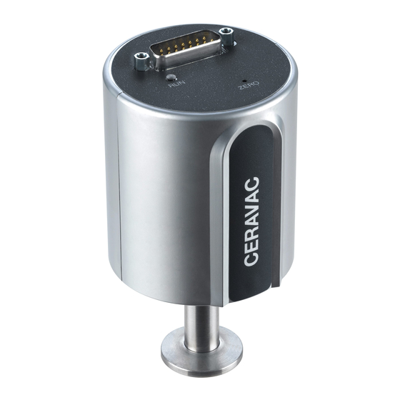
CERAVAC
Transmitter
CTR 100 N
Operating Manual 300544660_002_C1
Part Numbers:
230300V02
230301V02
230302V02
230303V02
230304V02
230305V02
230306V02
230307V02
230308V02
230309V02
230310V02
230311V02
230312V02
230313V02
230314V02
230315V02
230316V02
230317V02
230318V02
230319V02
230340V02
1
®
300544660_002_C1 11/2016 - © Leybold
Advertisement
Table of Contents

Subscribe to Our Youtube Channel
Related Manuals for LEYBOLD CERAVAC CTR 100 N


Summary of Contents for LEYBOLD CERAVAC CTR 100 N
- Page 1 ® CERAVAC Transmitter CTR 100 N Operating Manual 300544660_002_C1 Part Numbers: 230300V02 230301V02 230302V02 230303V02 230304V02 230305V02 230306V02 230307V02 230308V02 230309V02 230310V02 230311V02 230312V02 230313V02 230314V02 230315V02 230316V02 230317V02 230318V02 230319V02 230340V02 300544660_002_C1 11/2016 - © Leybold...
-
Page 2: Table Of Contents
Input/Output Wiring Electrical Connection Schematic Operations Pressure Output Analog Output Functions Interface Connector LED Status Indicator Vacuum Zero Adjustment FAQ (Frequently Asked Questions) Trouble Shooting Declaration of Contamination CE Declaration of Conformity Notes Sales and Service 300544660_002_C1 11/2016 - © Leybold... -
Page 3: Safety Information
Critical Explosive Environments. Do not use the transmitter in presence of flammable gases or other explosive environments. Corrosive Environments. The transmitter is intended for extended use in corrosive environments. Refer to Chapter 3 Section 3.3. 300544660_002_C1 11/2016 - © Leybold... - Page 4 Critical Service and Repair. Do not install substituted parts or perform any unauthorized modification to the instrument. Return the instrument to a Leybold Calibration and Service Center for service to ensure all of the safety features are maintained. Critical DANGER: Contaminated Parts Contaminated parts can be detrimental to health and the environment.
-
Page 5: Liability And Warranty
Wrong electrical connections can cause permanent damage to the transmitter or interference to measuring performance. Refer to Electrical connections in Chapter 4. 0.4 Liability and Warranty Leybold assumes no liability and the warranty becomes null and void if the end-user or third parties disregard the information in this document ... -
Page 6: Unpacking
1 pcs. English short form manual (P/N: 300544675_002_C1) 1 pcs. German short form manual (P/N: 300544675_001_C1) 1 pcs. Product Inspection and Test Report 1 pcs. User switch adjustment tool If any items are missing, please contact Leybold. 300544660_002_C1 11/2016 - © Leybold... -
Page 7: Description
For the benefit of the environment, at the end of life of the transmitter, it should not be disposed in the normal unsorted waste stream. It should be deposited at an appropriate collection point or facility to enable recovery or recycling. 300544660_002_C1 11/2016 - © Leybold... -
Page 8: Technical Data
(2) Resolution specification is best obtainable under ideal laboratory conditions. Actual resolution in service may vary. (3) The transmitter’s electronics are not sealed against entry of dust, rain, or snow, and therefore can be damaged by use outdoors 300544660_002_C1 11/2016 - © Leybold... -
Page 9: Available Configurations
Graphix Two 230681V01 230682V01 Graphix Three Cables Type C 5 Meter 12455 Cables Type C 10 Meter 230022 12456 Cables Type C 15 Meter Cables Type C 20 Meter 12457 Cables Type C 30 Meter 12458 300544660_002_C1 11/2016 - © Leybold... -
Page 10: Dimensions
2.4 Dimensions [mm] P/N: 230300V02 to 230319V02, Flanges: 230340V02 KF 16 CF 16 ½” Tube 8 VCR 3 Transmitter Installation (Mechanical) Caution 300544660_002_C1 11/2016 - © Leybold... -
Page 11: Conforming Utilization
Conversely, location close to a pumping system connection can cause a lower pressure measurement than actual chamber pressure. 300544660_002_C1 11/2016 - © Leybold... - Page 12 Bakeout Bakeout of the entire transmitter is not recommended, as the high temperatures may damage the electronics. The transmitter’s fitting only – not including the inlet tube - may be baked to 50° C. 300544660_002_C1 11/2016 - © Leybold...
- Page 13 If the transmitter will be exposed to pressures above atmospheric pressure, make sure that proper vacuum fittings are used. Ensure that the internal system pressure is at ambient pressure conditions before opening the vacuum system and removing any connections. 300544660_002_C1 11/2016 - © Leybold...
-
Page 14: Transmitter Installation (Electrical)
Analog signal output Reserved Reserved Power return for +24VDC supply Reserved +24VDC input power Reserved Reserved 4.2 Electrical Connection Schematic Transmitter identification +24VDC input power (alt) Analog signal return RS232, TxD RS232, RxD Chassis ground 300544660_002_C1 11/2016 - © Leybold... - Page 15 CTR100N Electrical Connection Ident/ Remote Zero Voltmeter Signal Output Signal Rtn Power In 14 to 30V Power Rtn Reserved Shielded to case 300544660_002_C1 11/2016 - © Leybold...
-
Page 16: Operations
Leybold recommends that the minimum control pressure using this transmitter should be 0.5% of the full-scale measurement range or 50 mV if the analog output signal is used for this control circuit. Attempting to control pressure below this minimum may result in less stable pressure control. -
Page 17: Analog Output
P (mbar) = 133.32*Pressure in Volts*Device Full Scale in Torr P (Pascal) = Pressure Units Conversion Transmitter Full-Scale Range - Torr mbar Pascal 0.133322 13.33224 1.333224 133.3224 13.33224 1333.224 26.66447 2666.447 133.3224 13332.24 1000 1333.224 133322.4 300544660_002_C1 11/2016 - © Leybold... - Page 18 Like all precision electromechanical measuring instruments, the transmitter requires periodic zeroing of its output to provide the best possible measurement accuracy. Leybold recommends that the transmitter be zeroed upon initial installation into the user’s process system to compensate for any drift that may have occurred during transportation and installation.
- Page 19 To reset all transmitter parameters, remove mains power from the device. Then press and hold the ZERO pushbutton for at least 5 seconds while reconnecting the mains power to the transmitter. This will reset all parameters in the transmitter’s memory back to the original default factory settings. 300544660_002_C1 11/2016 - © Leybold...
-
Page 20: Functions
The zero pushbutton is used to zero the analog and digital outputs of the transmitter. It can be used for this function at any pressure less than 20% of the transmitter’s full-scale measurement range. See Chapter 5 Operations under section 5.2 for further detailed information. 300544660_002_C1 11/2016 - © Leybold... -
Page 21: Faq (Frequently Asked Questions)
A: Check that the analog out is connected to a floating input and not an input that is connected to ground. If connected analog out return is connected to ground the supply current will flow in the signal line and cause voltage drop and ground looping. 300544660_002_C1 11/2016 - © Leybold... - Page 22 Q: How often does the transmitter require calibration or zero adjustment? A: Leybold recommends that the transmitter’s calibration be checked against a known pressure reference approximately every 12 months. Zeroing frequency is highly dependent on the application, and users must determine this empirically.
-
Page 23: Trouble Shooting
Transmitter exposed to heat or cooling air stream. Zero pushbutton does not work Pressure higher than 20% of full-scale measurement range. Electronics fault. Zero pushbutton is damaged (user induced). No analog output Power supply turned off. Check electrical connections. 300544660_002_C1 11/2016 - © Leybold... -
Page 24: Declaration Of Contamination
All dispatch instructions laid down in the manual must be followed e.g.: • Drain all service fluids • Remove filter elements • Seal all openings airtight • Pack / handle appropriately • Attach the declaration of contamination outside of the packaging 300544660_002_C1 11/2016 - © Leybold... - Page 25 Person to contact: Calibration: Factory-calibr. Phone : Fax: Quality test certificate DIN 55350-18-4.2.1 End user: A. Description of the Leybold product: Failure description: Material description : Catalog number: Additional parts: Serial number: Application-Tool: Type of oil (ForeVacuum-Pumps) : Application- Process: B.
-
Page 26: Ce Declaration Of Conformity
10 CE Declaration of Conformity 300544660_002_C1 11/2016 - © Leybold... -
Page 27: Notes
11 Notes 300544660_002_C1 11/2016 - © Leybold... -
Page 28: Sales And Service
12 Sales and Service 300544660_002_C1 11/2016 - © Leybold...
Need help?
Do you have a question about the CERAVAC CTR 100 N and is the answer not in the manual?
Questions and answers