Table of Contents
Advertisement
Quick Links
NF894V Series
User's Manual
NO. G03-NF894V-F
Revision: 1.0
Release date: April 18, 2022
Trademark:
* Specifications and Information contained in this documentation are furnished for information use only, and are
subject to change at any time without notice, and should not be construed as a commitment by manufacturer.
Advertisement
Table of Contents

Related Manuals for JETWAY NF894V Series


Summary of Contents for JETWAY NF894V Series
- Page 1 NF894V Series User’s Manual NO. G03-NF894V-F Revision: 1.0 Release date: April 18, 2022 Trademark: * Specifications and Information contained in this documentation are furnished for information use only, and are subject to change at any time without notice, and should not be construed as a commitment by manufacturer.
- Page 2 Environmental Protection Announcement Do not dispose this electronic device into the trash while discarding. To minimize pollution and ensure environment protection of mother earth, please recycle.
-
Page 3: Table Of Contents
TABLE OF CONTENT ENVIRONMENTAL SAFETY INSTRUCTION..............iii USER’S NOTICE ......................iv MANUAL REVISION INFORMATION ................iv ITEM CHECKLIST ......................iv CHAPTER 1 INTRODUCTION OF THE MOTHERBOARD FEATURE OF MOTHERBOARD ................1 SPECIFICATION ....................2 LAYOUT DIAGRAM ....................3 CHAPTER 2 HARDWARE INSTALLATION JUMPER SETTING .................... -
Page 4: Environmental Safety Instruction
Environmental Safety Instruction Avoid the dusty, humidity and temperature extremes. Do not place the product in any area where it may become wet. 0 to 40 centigrade is the suitable temperature. (The temperature comes from the request of the chassis and thermal solution) ... -
Page 5: User's Notice
USER’S NOTICE COPYRIGHT OF THIS MANUAL BELONGS TO THE MANUFACTURER. NO PART OF THIS MANUAL, INCLUDING THE PRODUCTS AND SOFTWARE DESCRIBED IN IT MAY BE REPRODUCED, TRANSMITTED OR TRANSLATED INTO ANY LANGUAGE IN ANY FORM OR BY ANY MEANS WITHOUT WRITTEN PERMISSION OF THE MANUFACTURER. -
Page 6: Chapter 1 Introduction Of The Motherboard
Chapter 1 Introduction of the Motherboard 1-1 Feature of Motherboard Onboard Intel ® Apollo Lake SoC Series Processor (Default J3455), with low power consumption and high performance Support 2* DDR3L 1866MHz SO-DIMM with maximum memory capacity up to ... -
Page 7: Specification
1-2 Specification Spec Description Mini-ITX form factor; 6-layers; PCB size: 17.0x17.0cm Design Intel ® Apollo Lake series SoC CPU (Default J3455) * For detailed CPU support information please visit our website 2* DDR3L SO-DIMM slot Support DDR3L1866 MHz SODIMM up to 8GB Memory Slot ... -
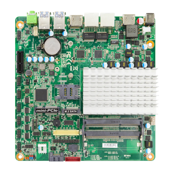
Page 8: Layout Diagram
1* Front panel header 1* Front panel audio header 1* 3W Amplifier wafer 1* LAN Status LED header 1* 9-Pin USB 2.0 header for 2* USB 2.0/1.1 ports 1* 4-Pin USB 2.0 header for 1* USB 2.0/1.1 port ... - Page 9 Motherboard Internal Diagram 9V~36V 32 GB CPUFAN DC-In EMMC Chip Connector Power Jack (optional) Internal 9V~36V HDMI2 Port DC-In Power Connector Intel CPU 2*DDR3L SODIMM Slot (SODIMM1/2) RJ-45 LAN Ports *M.2 Socket 3 Connector SMBUS (M2) Header HDMI1 Port (co-lay DP by order) INVERTER *SIM Card Wafer...
- Page 10 Motherboard Jumper Position JMPE JLED JLCD JCOM1 JAT_ATX1...
- Page 11 Connectors Connector Name DCIN3 9V~36V DC–in Power Jack HDMI2/HDMI1 HDMI Port Connector X2 LAN1/LAN 2 RJ-45 LAN Connector X2 USB30-1/USB30-2 USB 3.0 Port Connector X2 FP_HP Audio Line-out Port DCIN2 2-Pin Internal 9V~36V DC-in Power Connector SATA1 SATAIII Connector SATAPWR1 SATA Power out Connector CPUFAN1 CPU FAN Connector...
-
Page 12: Chapter 2 Hardware Installation
Jumper Jumper Name Description JCOM1 COM1 Port Pin9 Function Select 4-pin Block (2.0pitch) JLCD LCD Panel VCC Select 4-pin Block (2.0 pitch) JLED Inverter Backlight VCC Select 3-pin Block (2.54 pitch) JMPE MPE1 Slot VCC Select 3-pin Block (2.54 pitch) JAT_ATX1 ATX/AT Mode Select 3-pin Block (2.54 pitch) - Page 13 JLCD (4-pin): LCD Panel VCC Select (2.0 pitch) JLCD JLED (3-pin): LCD Backlight VCC Select (2.54 pitch) → JLED Inverter Backlight VCC Select JLED 1-2 Closed: Inverter 5V Selected; 2-3 Closed: Inverter 12V Selected...
- Page 14 JMPE (3-pin): MPE1 Slot VCC Select (2.54 pitch) JMPE JAT_AT1 (3-pin): ATX Mode/ AT Mode Select (2.54 pitch) JAT_ATX1 ATX Mode Selected: Press power button to power on after power input ready; AT Mode Selected: Directly power on as power input ready.
- Page 15 Pin 1&2 of J1(8-pin): Clear CMOS RAM Setting (2.0 pitch) Pin 3&4 of J1(8-pin): RTC Reset (2.0 pitch) → Pin 3&4 of J1 RTC Reset Pin1 3-4 Open: Normal(Default); Pin1 3-4 Closed: RTC Reset(One Touch).
- Page 16 Pin 5&6 of J1(8-pin): TXE Override (2.0 pitch) Pin 7&8 of J1(8-pin): Case Open Detection Select (2.0 pitch) Pin (7&8) Closed: When Case open function pin short to GND, the Case open function was detected. When used, needs to enter BIOS and enable ‘Case Open Detect’...
-
Page 17: Connectors, Headers And Wafers
Connectors, Headers and Wafers 2-2-1 Connectors (1) Rear Panel Connectors *Refer to Page-3. Icon Name Function 9V~36V DC–in system power connector DC-In Power Jack For user to connect compatible power adapter to provide power supply for the system. To connect display device that support HDMI HDMI Port specification. - Page 18 (2) DCIN2 (2-pin): Internal 9V~36V DC-in power connector DCIN2 Warning!! The board has a 9V~36V DC-in power jack (DCIN3) in I/O back panel and an internal 9V~36V power connector (DCIN2). User can only connect one type of compatible power supply to one of them to power the system.
- Page 19 (4) SATAPWR1 (4-pin) : SATA Power-out Connector SATAPWR1 (5) CPUFAN1 (4-pin): CPU FAN Connector CPUFAN1...
-
Page 20: Headers & Wafers
2-2-2 Headers & Wafers (1) JW_FP (9-pin): Front Panel Header (2.54 pitch) RSTSW PWRBTN PWRLED- HDDLED- HDDLED+ PWRLED+ JW_FP Pin 1 (2) FP_AUDIO (9-pin): Line-Out, MIC-In Header (2.0 pitch) This header connects to Front Panel Line-out, MIC-In connector with cable. FP_AUDIO... - Page 21 (3) AMP_SPK1 (4-pin): 3W Amplifier Wafer (2.54 pitch) AMP_SPK1 (4) JLANLED (4-pin): LAN Activity LED Headers (2.0 pitch) JLANLED...
- Page 22 (5) FP_USB20-1 (4-pin): USB 2.0 Port Header (2.0 pitch) FP_USB20-1 +DATA -DATA Pin1 (6) FP_USB20-2 (9-pin): USB 2.0 Port Header (2.0 pitch) FP_USB20-2...
- Page 23 (7) PS2KBMS (6-pin): PS/2 Keyboard & Mouse Port Header (2.0 pitch) Pin1 PS2KBMS...
- Page 24 (8) COM1/2/3/4/5/6 (9-pin): Serial Port Header (2.0 pitch) : COM1 RS232/422/485 Serial Port Header; : COM2/3/4/5/6 RS232 Serial Port Header. COM6 *COM1 COM2 COM4 COM3 COM5 *RS422 *RS485 Pin NO. RS232 DATA- Pin 1 DATA+ Pin 2 Pin 3 Pin 4 Pin 5 Pin 1 Pin 6...
- Page 25 (9) SMBUS (5-Pin): SMBUS Header (2.0 pitch) SMBUS (10) GPIO_CON (10-pin): GPIO Port Header (2.54 pitch) GPIO_87 GPIO_86 GPIO_84 GPIO_85 GPIO_82 GPIO_83 GPIO_81 GPIO_80 GPIO_CON Pin 1...
- Page 26 (11) eDP (40-pin): 4-Lane eDP Wafer (1.25 pitch) Pin NO. Pin Define Pin NO. Pin Define Pin 1 Pin 21 Pin 2 Pin 22 Pin 3 Lane3_N Pin 23 Pin 4 Lane3_P Pin 24 Pin 5 Pin 25 Pin 6 Lane2_N Pin 26 Pin 7...
- Page 27 (12) LVDS (32-Pin): 24-bit dual channel LVDS Header (2.0 pitch) LVDS Pin Define Pin NO. Pin NO. Pin Define GND Pin 32 Pin 31 LCD_VCC Pin 30 Pin 29 LCD_VCC XX Pin 28 Pin 27 LCD_VCC LVDSA -DATAN0 Pin 26 Pin 25 LVDSA-DATAP0 LVDSA -DATAN1 Pin 24...
- Page 28 (13) INVERTER (8-Pin): LVDS Inverter (2.54 pitch) INVERTER Warning! Find Pin-1 location of the inverter and make sure that the installation direction is correct! Otherwise serious harm will occur to the board/display panel!! (14) JSIM(6-Pin): SIM Card Expansion Header (2.0 pitch) JSIM...
-
Page 29: Chapter 3 Introducing Bios
Chapter 3 Introducing BIOS Notice! The BIOS options in this manual are for reference only. Different configurations may lead to difference in BIOS screen and BIOS screens in manuals are usually the first BIOS version when the board is released and may be different from your purchased motherboard. Users are welcome to download the latest BIOS version form our official website. -
Page 30: Bios Menu Screen
Press <Del> to enter Setup/ Press <F7> to enter Popup Menu. BIOS Menu Screen The following diagram show a general BIOS menu screen: Menu Bar General Help Items Current Setting Value Menu Items Function Keys... -
Page 31: Function Keys
Function Keys In the above BIOS Setup main menu of, you can see several options. We will explain these options step by step in the following pages of this chapter, but let us first see a short description of the function keys you may use here: ... -
Page 32: Main Menu
Chipset To change chipset configuration Security Password settings Boot To change boot settings Save & Exit Save setting, loading and exit options. User can press the right or left arrow key on the keyboard to switch from menu bar. The selected one is highlighted. Main Menu Main menu screen includes some basic system information. -
Page 33: Advanced Menu
System Date Set the date. Please use [Tab] to switch between date elements. System Time Set the time. Please use [Tab] to switch between time elements. 3-7 Advanced Menu OS Selection The optional settings: [Windows]; [Intel Linux]; [MSDOS]. * Note: User need to go to this item to select the OS mode before installing corresponding OS driver, otherwise problems will occur when installing the driver. - Page 34 Security Device Support Use this item to enable or disable BIOS support for security device. The optional settings: [Disabled]; [Enabled]. No Security Device Found ► ACPI Settings Press [Enter] to make settings for the following sub-items: ACPI Settings ACPI Sleep State Use this item to select the highest ACPI sleep state the system will enter when the suspend button is pressed.
- Page 35 ► Serial Port 2 Configuration Press [Enter] to make settings for the following sub-items: Serial Port Use this item to enable or disable serial port (COM). The optional settings are: [Disabled]; [Enabled]. When set as [Enabled], the following sub-items shall appear: Device Settings Change Settings Use this item to select an optimal setting for super IO device.
- Page 36 ERP Support The optional settings: [Disabled]; [Enabled]. This item should be set as [Disabled] if you wish to have all active wake-up functions. Case Open Detect Use this item to detect case has already open or not, show message in POST. The optional settings: [Disabled];...
- Page 37 supply. Use needs to select ‘AT or ATX Mode’ on MB jumper at first (refer to Page 9, jumper JAT_AT1 setting Pin 1&2 of for ATX Mode & Pin 2&3 of AT Mode Select). Serial Port Console Redirection COM1 Console Redirection The optional settings: [Disabled];...
- Page 38 Stop Bits Stop bits indicate the end of a serial data packet. (A start bit indicates the beginning). The standard setting is 1 stop bit. Communication with slow devices may require more than 1 stop bit. The optional settings: [1]; [2]. Flow Control Flow control can prevent data loss from buffer overflow.
- Page 39 Enable. Serial Port for Out-of-Band Management/ Windows Emergency Management Services (EMS) Console Redirection The optional settings: [Disabled]; [Enabled]. When set as [Enabled], the following sub-items shall appear: Console Redirection Settings The settings specify how the host computer and the remote computer (which the user is using) will exchange data.
- Page 40 *This item may or may not show up, depending on different configuration. Parity The default setting is: [None]. *This item may or may not show up, depending on different configuration. Stop Bits The default setting is: [1]. *This item may or may not show up, depending on different configuration. ►...
- Page 41 VT-d Use this item to enable or disable CPU VT-d. The optional settings: [Enabled]; [Disabled]. EIST Use this item to enable or disable Intel SpeedStep. The optional settings: [Disabled]; [Enabled]. When set as [Enabled], the following sub-items shall appear: Turbo Mode The optional settings: [Disabled];...
- Page 42 optional will not be created. Ipv6 PXE Support The optional settings are: [Disabled]; [Enabled]. Use this item to enable Ipv6 PXE Boot Support. When set as [Disabled], Ipv6 boot optional will not be created. PXE Boot Wait Time Use this item to set wait time to press [ESC] key to abort the PXE boot. Media Detect Count Use this item to set number of times presence of media will be checked.
- Page 43 The optional settings: [Disabled]; [Enabled]. When set as [Enabled], system will wake on the hour/min/sec specified. Wake-up Hour Use this item to 0-23 For example, 3 for 3am and 15 for 3pm. Wake-up Minute Use this item to Displays and changes the System Time from the Real-Time Clock. Clock is displayed in 24-hour format.
- Page 44 **Note:Please disable ERP before activating this function in S4 The optional settings: [Enabled]; [Disabled]. USB Configuration Press [Enter] to make settings for the following sub-items: USB Configuration USB Devices: 1 keyboard Legacy USB Support The optional settings are: [Enabled]; [Disabled]; [Auto]. [Enabled]: To enable legacy USB support.
-
Page 45: Chipset Menu
The delay range is from [1] to [40] seconds, in one second increments. Platform Trust Technology TPM Configuration fTPM Use this item to Enable/Disable fTPM The optional settings are: [Disabled]; [Enabled] ► Intel(R) Ethernet Controller I225-V-XX:XX:XX:XX:XX:XX ► Intel(R) Ethernet Controller I225-V -XX:XX:XX:XX:XX:XX These items show current network brief information. - Page 46 The optional settings are: [2MB]; [4MB]; [8MB]. DVMT Pre-Allocated Use this item to select DVMT 5.0 pre-allocated (fixed) graphics memory size used by the internal graphics device. The optional settings are: [64M]; [96M]; [128M]; [160M]; [192M]; [224M]; [256M]; [288M]; [320M]; [352M]; [384M]; [416M]; [448M]; [480M]; [512M]. DVMT Total Gfx Memory Use this item to select DVMT 5.0 total graphics memory size used by the internal graphics device.
- Page 47 The optional settings are: [Auto]; [HDMI1]; [HDMI2]. Secondary IGFX Boot Display Use this item to select Secondary Display Device. The optional settings are: [Disabled]; [HDMI1]; [HDMI2] Memory Configuration The working memory information will be on display. ► South Cluster Configuration ...
- Page 48 HD-Audio Support Use this item to enable or disable HD-Audio Support. The optional settings are: [Disabled]; [Enabled]. SCC eMMC Support Use this item to enable or disable SCC eMMC Support. The optional settings are: [Disabled]; [Enabled]. **Note: ‘SCC eMMC Support’ item is optional for boards with EMMC integrated. eMMC Max Speed Use this item to select the eMMC max speed allowed.
-
Page 49: Security Menu
3-9 Security Menu Security menu allow users to change administrator password and user password settings. Administrator Password If there is no password present on system, please press [Enter] to create new administrator password. If password is present on system, please press [Enter] to verify old password then to clear/change password. - Page 50 Secure Boot Press [Enter] to make customized secure settings: Secure Boot Control The optional settings are: [Disabled]; [Enabled]. Secure Boot can be enabled if 1. System running in user mode with enrolled Platform Key (PK); 2. CSM function is disabled. Secure Boot Mode The optional settings are: [Standard];...
-
Page 51: Boot Menu
2. Authenticated UEFI Variable ** Key: Vendor, Custom, Mixed, Test(*) modified from Setup menu 3-10 Boot Menu Setup Prompt Timeout Use this item to set number of seconds to wait for setup activation key. Bootup Numlock State Use this item to select keyboard numlock state. The optional settings are: [On];... -
Page 52: Save & Exit Menu
The optional settings are: [Windows Boot Manager (MMC- BJTD4R)]; [MMC- BJTD4R]; [UEFI: Built- in EFI Shell]; [Disabled] Hard Drive BBS Priorities Use this item to set the order of the legacy devices in the available group Press [Enter] to make settings for the following sub-items: Boot Option #1 Use this item to Sets the system boot order The optional settings are: [MMC- BJTD4R];... - Page 53 Use this item to save the changes done so far as user defaults. Restore User Defaults Use this item to restore defaults to all the setup options. Boot Override The available options here are dynamically updated and make system boot to any boot option selected.
Need help?
Do you have a question about the NF894V Series and is the answer not in the manual?
Questions and answers