Table of Contents
Advertisement
Quick Links
NF631 Series
User's Manual
P/N: G03-NF631-F
Revision: 3.0
Release date: October 1, 2019
Trademark:
* Specifications and Information contained in this documentation are furnished for information use only, and are
subject to change at any time without notice, and should not be construed as a commitment by manufacturer.
Advertisement
Table of Contents

Related Manuals for JETWAY NF631 Series


Summary of Contents for JETWAY NF631 Series
- Page 1 NF631 Series User’s Manual P/N: G03-NF631-F Revision: 3.0 Release date: October 1, 2019 Trademark: * Specifications and Information contained in this documentation are furnished for information use only, and are subject to change at any time without notice, and should not be construed as a commitment by manufacturer.
- Page 2 Environmental Protection Announcement Do not dispose this electronic device into the trash while discarding. To minimize pollution and ensure environment protection of mother earth, please recycle.
-
Page 3: Table Of Contents
TABLE OF CONTENT ENVIRONMENTAL SAFETY INSTRUCTION ................iv USER’S NOTICE ........................v MANUAL REVISION INFORMATION ..................v ITEM CHECKLIST ........................v CHAPTER 1 INTRODUCTION PRODUCT FEATURES ....................1 SPECIFICATION ......................2 LAYOUT DIAGRAM ....................3 CHAPTER 2 HARDWARE INSTALLATION JUMPER SETTINGS ....................9 CONNECTORS AND HEADERS ................ -
Page 4: Environmental Safety Instruction
Environmental Safety Instruction Avoid the dusty, humidity and temperature extremes. Do not place the product in any area where it may become wet. 0 to 60 centigrade is the suitable temperature. (The figure comes from the request of the main chipset) ... -
Page 5: User's Notice
USER’S NOTICE COPYRIGHT OF THIS MANUAL BELONGS TO THE MANUFACTURER. NO PART OF THIS MANUAL, INCLUDING THE PRODUCTS AND SOFTWARE DESCRIBED IN IT MAY BE REPRODUCED, TRANSMITTED OR TRANSLATED INTO ANY LANGUAGE IN ANY FORM OR BY ANY MEANS WITHOUT WRITTEN PERMISSION OF THE MANUFACTURER. -
Page 6: Chapter 1 Introduction
Chapter 1: Introduction Product Features ® Onboard Intel Apollo Lake Series Processor, with low power consumption and high performance Support 1 * SO-DIMM, up to 8GB memory Support 2 * DP and 1 * eDP display ports, max 4K resolution ... -
Page 7: Specification
Specification Spec Description ® Intel Apollo Lake series CPU 1 * DDR3L 1600MHz SO-DIMM up to 8GB DRAM Memory 1 * full-size Mini-PCIE slot Expansion Slot 1 * SATA III (6Gb/s) Connector 1 * M.2 slot (M key 2242) Storage ... -
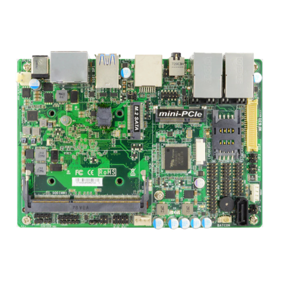
Page 8: Layout Diagram
Layout Diagram Rear IO Panel Diagram: RJ-45 LAN Ports USB 3.0 Ports Line out (RJ-45 Type) & MIC 12V DC-in Power Jack DP Ports USB 3.0 Ports Micro- SD card socket... - Page 9 Internal Diagram-Front Side: SATA Power-out EDP Header Connector SATAIII Port Top: RJ-45 LAN Port Connector Bottom: USB 3.0 Port USB 2.0 Top: RJ-45 LAN Port Ports Header Bottom: USB 3.0 Port Serial Ports GPIO Port *SIM Card Header Slot Line out & MIC Full-size Mini-PCIE Slot SPDIFOUT Header...
- Page 10 Internal Diagram-Back Side: Micro-SD Card Socket Intel CPU *Note: CPU is the most important part of the board and very fragile to any possible harm. Make sure that there is no damage to the CPU during any installation procedures!
- Page 11 Motherboard Jumper Positions: AT_MODE JBAT...
- Page 12 Jumper Jumper Name Description COM1 Port Pin9 Function 4-Pin Block MPE Slot Power 3-Pin Block eDP LCD Power 4-Pin Block eDP Inverter Power 4-Pin Block COM2 Pin9 Function 4-Pin Block Case Open and TXE Function Select 4-Pin Block AT_MODE ATX/AT Mode Select 3-Pin Block JBAT CMOS Clear Setting...
- Page 13 Headers Header Name Description EDP Header 40-pin Block FP_AUDIO Front Panel Header(PWR LED/ HD 9-pin Block LED/Power Button /Reset) SPDIFOUT HDMI S/PDIF-out Header 2-pin Block USB2 USB 2.0 Port Header 9-pin Block COM2/3/4/5/6 Serial Port Header 9-pin Block GPIO GPIO Port Header 10-pin Block Front Panel Header 8-pin Block...
-
Page 14: Chapter 2 Hardware Installation
Chapter 2: Hardware Installation 2-1 Jumper Settings JP1 (4-pin): COM1 Port Pin9 Function Select → COM1 Port Pin-9 2-4 Closed: 3-4 Closed: 4-6 Closed: RI=NC; RI= 5V; RI= 12V. JP2 (3-pin): MPE Slot Power Select JP2 → MPE Slot Power 1-2 Close: 3.3V Selected(Default);... - Page 15 JP3 (4-pin): eDP LCD Power Select JP3→eDP LCD VCC 2 4 6 2 4 6 2 4 6 2-4 Closed: eDP 3-4 Closed: eDP 4-6 Closed: eDP LCD VCC= 3.3V LCD VCC= 5V; LCD VCC= 12V. (default); JP4 (4-pin): eDP Inverter Power Select JP4→eDP Inverter VCC 2 4 6 2 4 6...
- Page 16 JP5 (4-pin): COM2 Pin9 Function Select JP5→ COM2 Pin9 Select 2 4 6 2 4 6 2 4 6 2-4 Closed: 3-4 Closed: 4-6 Closed: RI = RS232 RI = 12V. RI = 5V; (default); JP6 (4-pin): Case Open and TXE/ME Select →...
- Page 17 AT_MODE (3-pin): AT/ATX Mode Function Select → AT_MODE AT/ATX Mode Select AT_MODE 1-2 Closed: ATX Mode Selected; 2-3 Closed: AT Mode Selected. *ATX Mode Selected: Press power button to power on after power input ready; AT Mode Selected: Directly power on as power input ready. JBAT (2-pin): CMOS Clear Setting JBAT→...
-
Page 18: Connectors And Headers
Connectors and Headers 2-2-1 Connectors (1) Rear Panel Connectors RJ-45 LAN Ports USB 3.0 Ports Line out (RJ-45 Type) & MIC 12V DC-in Power Jack DP Ports USB 3.0 Ports Micro SD Card Socket Icon Name Function This connector is standard RJ-45 LAN jack for Network RJ-45 LAN Port connection. - Page 19 To the system to corresponding display device with compatible DP cable. Display Port 12V DC–in system power connector Power Connector For user to connect compatible power adapter to provide power supply for the system. (2) DCIN3 (2-pin block):Internal 12V DC-in Power Connector DCIN3 (3) PWROUT (4-pin): SATA Power Connector PWOUT...
- Page 20 (4) SATA (7-pin Block): SATAIII Port connector The board comes with a SATAIII port that supports 6GB/s transfer rate. SATA Pin No. Definition (5) CPUFAN (4-pin): CPU FAN Connector CPUFAN...
-
Page 21: Headers
2-2-2 Headers (1) EDP (40-pin): eDP Header Pin21 Pin40 Pin20 Pin1 Pin NO. Pin Define Pin NO. Pin Define Pin 1 Pin 21 Pin 2 Pin 22 Pin 3 Lane3_N Pin 23 Pin 4 Lane3_P Pin 24 Pin 5 Pin 25 Pin 6 Lane2_N Pin 26... - Page 22 (2) FP_AUDIO (9-pin): Line-Out, MIC-In Header This header connects to Front Panel Line-out, MIC-In connector with cable. Pin 1 MIC2-L RESERVE MIC2-R LINE OUT2-R MIC_RTU SENSE_B LINE OUT2-L LINEOUT2_ FP_AUDIO (3) SPDIFOUT (2-pin): HDMI SPDIF Out Header Pin1 SPDIFOUT...
- Page 23 (4) USB2 (9-pin): USB 2.0 Port Pin Header Pin 1 USB2 (5) COM2/3/4/5/6 (9-pin): Serial Port Headers COM2 COM3 Pin NO. RS232 *RS422 *RS485 Pin 1 DATA- Pin 2 DATA+ Pin 3 Pin 4 Pin 5 Pin 6 Pin 7 COM4 COM6 COM5...
- Page 24 *Notice: RS422, RS485 function is supported by COM2 header only, with compatible COM cable for RS422 or RS 485 function. User also needs to go to BIOS to set ‘Transmission Mode Select’ for COM2. (6) GPIO (10-pin): GPIO Header Pin 1 GPIO (7) FP (8-pin): Front Panel Header PWRBTN...
- Page 25 (8) PS2KBMS (6-pin): PS/2 Keyboard & Mouse Header MS_CLK MS_DATA KB_DATA PS2KBMS Pin 1 KB_CLK (9) SMBUS (5-pin): SMBUS Header 3VSB SMBUS_ALERT SMBUS_DATA SMBUS_CLK SMBUS Pin 1...
- Page 26 (10) I2C(4-pin): I2C Header I2C_DATA I2C_CLK 3.3V Pin 1...
-
Page 27: Chapter 3: Bios Setting
Chapter 3: BIOS SETTING Notice! The BIOS options in this manual are for reference only. Different configurations may lead to difference in BIOS screen and BIOS screens in manuals are usually the first BIOS version when the board is released and may be different from your purchased motherboard. Users are welcome to download the latest BIOS version form our official website. -
Page 28: Bios Menu Screen
BIOS Menu Screen The following diagram show a general BIOS menu screen: Menu Bar General Help Items Current Setting Value Function Keys Menu Items BIOS Menu Screen... -
Page 29: Function Keys
Function Keys In the above BIOS Setup main menu of, you can see several options. We will explain these options step by step in the following pages of this chapter, but let us first see a short description of the function keys you may use here: ... -
Page 30: Getting Help
Getting Help Main Menu The on-line description of the highlighted setup function is displayed at the top right corner the screen. Status Page Setup Menu/Option Page Setup Menu Press F1 to pop up a small help window that describes the appropriate keys to use and the possible selections for the highlighted item. -
Page 31: Main Menu
Main Menu Main menu screen includes some basic system information. Highlight the item and then use the <+> or <-> and numerical keyboard keys to select the value you want in each item. System Date Set the date. Please use [Tab] to switch between date elements. System Time Set the time. -
Page 32: Advanced Menu
3-7 Advanced Menu OS Selection The optional settings: [Windows]; [Intel Linux]; [MSDOS]. * Note: User need to go to this item to select the OS mode before installing corresponding OS driver, otherwise problems will occur when installing the driver. Trusted Computing Press [Enter] to make settings for the following sub-item: Configuration Security Device Support... - Page 33 Use this item to select the enable or disable BIOS support security devices. The optional setting are: [Enabled]; [Disabled] ACPI Settings Press [Enter] to make settings for the following sub-item: ACPI Settings ACPI Sleep State Use this item to select the highest ACPI sleep state the system will enter when the suspend button is pressed.
- Page 34 Super IO Configuration ERP Support The optional setting are: [Disabled] ; [Auto] This item should be set as [Disabled] if you wish to have all active wake-up functions. Serial Port 1/3/4/5/6 Configuration Press [Enter] to make settings for the following items: Serial Port Use this item to [Enabled] or [Disabled] serial port (COM).
- Page 35 Use this item to [Enabled] or [Disabled] WatchDog Timer Control. When set as [Enabled], the following sub-items shall appear: WatchDog Timer Value User can set a value in the range of [4] to [255]. WatchDog Timer Unit The optional settings are: [Sec.]; [Min.]. WatchDog Wake-up Timer in ERP This item support WDT wake-up while ERP function is set as [Enabled].
- Page 36 ► SmartFAN Configuration Press [Enter] to make settings for SmartFan Configuration: SmartFAN Configuration CPUFAN Type The optional settings are: [3-Pin]; [4-Pin]. CPUFAN Smart Mode The optional settings are: [Disabled]; [Enabled]. When set as [Enabled], the following sub-items shall appear: CPUFAN Full-Speed Temperature Use this item to set CPUFAN (/SYSFAN1/SYSFAN2) full speed temperature.
- Page 37 Console Redirection Settings The settings specify how the host computer and the remote computer (which the user is using) will exchange data. Both computers should have the same or compatible settings. Press [Enter] to make settings for the following sub-items: Terminal Type The optional settings are: [VT100];...
- Page 38 Legacy Console Redirection Settings Press [Enter] to make settings in ‘Legacy Serial Redirection Port’. Legacy Serial Redirection Port Use this item to select a COM port to display redirection of Legacy OS and Legacy OPROM messages. The optional settings: [COM1]. Serial Port for Out-of-Band Management/ Windows Emergency Management Services (EMS) Console Redirection...
- Page 39 Stop Bits The default setting is: [1]. *This item may or may not show up, depending on different configuration. CPU Configuration Press [Enter] to view current CPU configuration and make settings for the following sub-items: Intel Virtualization Technology The optional settings: [Disabled]; [Enabled]. VT-d The optional settings: [Disabled];...
- Page 40 Use this item to enable Ipv4 PXE Boot Support. When set as [Disabled], Ipv4 PXE boot optional will not be created. Ipv4 HTTP Support The optional settings are: [Disabled]; [Enabled]. Use this item to enable Ipv4 HTTP Boot Support. When set as [Disabled], Ipv4 HTTP boot optional will not be created.
- Page 41 Video This item controls the execution of UEFI and Legacy Video OpROM. The optional settings are: [UEFI]; [Legacy]. Other PCI devices This item determines OpROM execution policy for devices other than Network, storage or video. The optional settings are: [Do not launch]; [UEFI]; [Legacy]. ...
- Page 42 Use this item to set USB mass storage device start unit command time-out. The optional settings are: [10 sec]; [20 sec]; [30 sec]; [40 sec]. Device Power-up Delay Use this item to set maximum time the device will take before it properly reports itself to the host controller.
-
Page 43: Chipset Menu
3-8 Chipset Menu Uncore Configuration Press [Enter] to make settings for the following sub-items: GOP Configuration GTT Size The optional settings: [2MB]; [4MB]; [8MB]. DVMT Pre-Allocated The optional settings: [64MB]; [96MB]; [128MB]; …… [480MB]; [512MB]. DVMT Total Gfx Mem The optional settings: [128MB];... - Page 44 Brightness Level The optional settings: [20]; [40]; [60]……. [240]; [255]. South Cluster Configuration Press [Enter] to make settings for the following sub-items: SATA Configuration SATA Controller The optional settings: [Enabled]; [Disabled]. SATA Speed Support The item is for user to set the maximum speed the SATA controller can support. The optional settings are: [Gen1];...
-
Page 45: Security Menu
3-9 Security Menu Security menu allow users to change administrator password and user password settings. Secure Boot Press [Enter] to make settings for the following sub-items: Secure Boot Control The optional settings: [Disabled]; [Enabled]. Secure Boot Mode The optional settings: [Standard]; [Custom]. When set as [Standard], BIOS will install factory default keys. - Page 46 Key Management Press [Enter] to make settings for the following items: Provision Factory Defakt Keys The optional settings: [Disabled]; [Enabled]. Enroll all Factory Default Keys The optional settings: [Yes]; [No]. Press [Yes] to install default keys. Save all Secure Boot Variables Press [Enter] to save secure boot variables.
-
Page 47: Boot Menu
3-10 Boot Menu Setup Prompt Timeout Use this item to set number of seconds to wait for setup activation key. Bootup Numlock State Use this item to select keyboard numlock state. The optional settings are: [On]; [Off]. Quiet Boot The optional settings are: [Disabled]; [Enabled]. Boot Option Priorities Boot Option#1/2…... -
Page 48: Save & Exit Menu
3-11 Save & Exit Menu Save Changes and Reset This item allows user to reset the system after saving the changes. Discard Changes and Reset This item allows user to reset the system without saving any changes. Restore Defaults Use this item to restore /load default values for all the setup options. Save as User Defaults Use this item to save the changes done so far as user defaults. - Page 49 Boot Override UEFI:xx/… Press this item to select the device as boot disk after save configuration and reset. Launch EFI Shell from filesystem device This item is used for attempts to launch EFI shell application from one of the available file system devices.
-
Page 50: Chapter 4: Gpio And Watchdog Sample Code
Chapter 4: GPIO and WATCHDOG SAMPLE Code 4-1 WATCHDOG SAMPLE CODE Please go to the following web site. Then, click “Driver” to get the watchdog sample code: http://www.jetwayipc.com/search.asp?keys=NF631 4-2 GPIO SAMPLE CODE Please go to the following web site. Then, click “Driver” to get the GPIO sample code: http://www.jetwayipc.com/search.asp?keys=NF631...
Need help?
Do you have a question about the NF631 Series and is the answer not in the manual?
Questions and answers