COZY CF403D-H Installation And Operating Instructions Manual
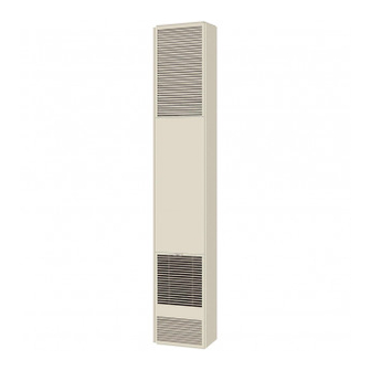
Counterflow wall furnace
Hide thumbs
Also See for CF403D-H:
- Installation and operating instructions manual (85 pages) ,
- Installation and operating instructions manual (28 pages)
Table of Contents
Advertisement
R
24 VOLT SYSTEM
WITH LOW-BTU
PILOT
24 VOLT SYSTEM
WITH INTERMITTENT
IGNITION (I.I.D.)
WARNING: If the information in this manual is not followed exactly, a fire or
explosion may result causing property damage, personal injury or loss of life.
-
Do not store or use gasoline or other flammable vapors and liquids in the
vicinity of this or any other appliance.
WHAT TO DO IF YOU SMELL GAS:
Do not try to light any appliance.
Do not touch any electrical switch; do not use any phone in your building.
Immediately call your gas supplier from a neighbor's phone.
Follow the gas supplier's instructions.
If you cannot reach your gas supplier, call the fire department.
-
INSTALLATION AND SERVICE MUST BE PERFORMED
BY A QUALIFIED INSTALLER, SERVICE AGENCY OR
THE GAS SUPPLIER.
WARNING: Operation of this furnace when not connected to a properly installed and maintained venting
system can result in Carbon Monoxide (C.O.) poisoning and possible death. For your safety, this furnace
and the venting system should be inspected at least annually by a qualified service technician.
The coating selected to provide longer life to the heat exchanger may smoke slightly upon initial firing. Please provide
adequate ventilation if this occurs.
This unit is for residential use only and is not approved for installation in mobile homes, greenhouses, or environments involving
dusty, wet, corrosive, or explosive conditions. Such conditions will invalidate the warranty and may create unsafe conditions.
Installation, maintenance, service, troubleshooting and repairs must be performed by a qualified service agency. Mr./
Mrs. Homeowner, DO NOT attempt any of these procedures yourself as this could expose you to property damage,
personal injury or loss of life and will invalidate all warranties.
INSTALLATION AND
OPERATING INSTRUCTIONS
P/N 78111 / REV. 06/2013
MODEL NUMBERS
NATURAL GAS
L.P. GAS
NATURAL GAS
L.P. GAS
INSTALLER: Leave this manual with the appliance.
CONSUMER: Retain this manual for future reference.
COUNTERFLOW
WALL FURNACE
CF403D-H CF553D-H
CF404D-H CF554D-H
CF407D-H CF557D-H
CF408D-H CF558D-H
This appliance is equipped
with a blocked flue switch
designed to protect against
improper venting of combus-
tion products.
THIS UNIT IS NOT TO BE
INSTALLED IN MOBILE
HOMES.
R
Advertisement
Table of Contents

Related Manuals for COZY CF403D-H


Summary of Contents for COZY CF403D-H
-
Page 1: Operating Instructions
COUNTERFLOW WALL FURNACE INSTALLATION AND OPERATING INSTRUCTIONS P/N 78111 / REV. 06/2013 MODEL NUMBERS 24 VOLT SYSTEM NATURAL GAS CF403D-H CF553D-H WITH LOW-BTU PILOT L.P. GAS CF404D-H CF554D-H 24 VOLT SYSTEM NATURAL GAS CF407D-H CF557D-H WITH INTERMITTENT IGNITION (I.I.D.) L.P. GAS... -
Page 2: Table Of Contents
Shipping Number Control Gas Input (Oval) Inlet Finished Dimensions Speed Amps CFM Weight MODELS WITH LOW-BTU STANDING PILOT CF403D-H 24 Volt Nat. 40,000 4” ½” 14-5/16”Wx10¼”Dx81-5/16”H 2 2.25 104 Lbs. CF404D-H 24 Volt L.P. 40,000 4” ½” 14-5/16”Wx10¼”Dx81-5/16”H 2 2.25 104 Lbs. -
Page 3: Safety Rules
SAFETY RULES Improper installation, adjustment, alteration, service or maintenance can cause property damage, bodily injury or death. If you do not understand these instructions or your local codes, call local authorities, a qualified installer, service agency, gas supplier, or the manufacturer. Do not install this fan type wall furnace in a recreational vehicle trailer or mobile home. - Page 4 VENTING - CONTINUED More than 10’ 10’ or Height above any Less roof surface 10’ within 10’ horizontally Ridge 2’ Min. 2’ Min. Ridge 3’ Min. 3’ Min. Chimney Chimney FIGURE A This appliance is equipped with a blocked flue switch. Listed Vent Top 2’...
-
Page 5: Combustion And Ventilation Air
COMBUSTION AND VENTILATION AIR ALL COMBUSTION AIR FROM ADJACENT INDOOR SPACES THROUGH INDOOR COMBUSTION AIR OPENINGS When installed, this gas appliance must be provided with fresh UL Listed Vent Cap air for combustion, ventilation, and dilution of hot flue gases. UL Listed Gas Vent The minimum required volume of the area where the appliance is installed should be 50 cubic feet per 1,000 btu/hr. -
Page 6: Rough-In Instructions
USING ADJACENT STUD SPACE FOR ALL LOCATION AND SPECIAL PRECAUTIONS COMBUSTION AIR FROM OUTSIDE The wall furnace should be located near the center of the HOLES CONNECTING TO area to be heated for optimal heat distribution. VENTILATED ATTIC If the wall furnace is installed directly on carpeting, tile or any CEILING combustible material other than wood flooring, the wall fur- PLATE... - Page 7 GAS ROUGH-IN Check local codes for requirements as to the size and type of To heater gas control valve gas line required. See Figure 5 for location of gas inlet holes in furnace cabinet. Compounds used on threaded joints of gas pipe should be Manual cut off valve resistant to the action of liquefied petroleum gases.
-
Page 8: Installation
INSTALLATION / WHEN RECESSED INSTALLATION (UP TO 9-1/4”) WHEN INSTALLED FLUSH TO WALL STEP 1.Cut out floor plate between 2x4 studs, so heater STEP 1.After locating furnace, cut 3-1/2”x12” rectangular hole will set flat on floor. in ceiling between ceiling joists. Make sure gasket is in STEP 2.Make electrical connection of 115 V. -
Page 9: Controls
Installation of B-W Gas Vent Firestop spacers supplied Installation of B-W Gas Vent for one-story buildings or for Ceiling plate spacers to center by manufacturer of B-W for each subsequent ceiling or first floor of multi-story B-W Gas Vent in stud space - Gas Vent floor level of multistory buildings. -
Page 10: Lighting & Re-Lighting Instructions
CF403D-H, CF404D-H, CF553D-H, CF554D-H - - STANDING PILOT FOR YOUR SAFETY READ BEFORE LIGHTING WARNING: If you do not follow these instructions exactly, a fire or explosion may result causing property damage, personal injury or loss of life. • If you cannot reach your gas supplier, call the fire A. - Page 11 CF407D-H, CF408D-H, CF557D-H, CF558D-H - - I.I.D. PILOT FOR YOUR SAFETY READ BEFORE LIGHTING WARNING: If you do not follow these instructions exactly, a fire or explosion may result causing property damage, personal injury or loss of life. • If you cannot reach your gas supplier, call the fire A.
-
Page 12: Operation
OPERATION PROPER BURNER FLAME This heater is equipped with a slow opening gas control. A proper flame will have a dark blue inner mantle On a call for heat the gas valve does not snap-open to that sits right on top of the burners with a lighter full manifold pressure, but opens with a gradual increase blue outer mantle rising above the burner, (See to normal manifold pressure. -
Page 13: Terminal Block Wiring Diagram
MOTOR (Green) POWER CORD (Black) P/N 91123 CF403D-H, CF404D-H, CF407D-H, CF408D-H, CF553D-H, CF554D-H, CF557D-H, CF558D-H CAUTION: Label all wires prior to disconnection when servicing controls. Wiring errors can cause improper and dangerous operation. Verify proper operation after servicing. AUXILIARY LIMIT SWITCH For your safety this furnace is equipped with a manual reset auxiliary limit switch. -
Page 14: Wiring Diagram
AUXILIARY SWITCH SWITCH SWITCH SWITCH SWITCH SWITCH LIMIT SWITCH BLACK BLACK PILOT AUXILIARY LIMIT SWITCH BLACK GAS VALVE CF403D-H, CF404D-H Spark Sense CF553D-H, CF554D-H 24 V 24 V Gnd. PICTORIAL Gnd.(Burner) SCHEMATIC MV/PV GAS VALVE AMPS MODEL NO. AMPS 2.25 CF407/557D-H 2.55... -
Page 15: Side & Rear Discharge Kits
ROUGH-INS FOR REAR OR SIDE DISCHARGE Install plastergrounds as shown in Figure 12 and Figure 13. This kit must be installed by a qualified installer or service technician. NOTE: When side discharge is being used, furnace should be set exactly 4” from side wall. Plaster Ground 1/2”... - Page 16 OPTIONAL KITS - CONTINUED This kit must be installed by a qualified installer or service technician. SIDE DISCHARGE (With Extension Boot) SIDE DISCHARGE ON CASING Use optional kit No. 30SRB-A. Use optional kit No. 306SR-A. Cut opening in drywall as shown in Fig. 17. Cut out and remove embossed area on casing side.
-
Page 17: Trouble Shooting Chart
TROUBLE SHOOTING CHART for qualified service technician - MAIN BURNER SYMPTOM POSSIBLE CAUSES CORRECTIVE ACTION Flame too large 1. Defective operator section of gas valve. 1. Replace complete valve. 2. Burner orifice too large. 2. Check with local gas company for proper orifice size and replace. -
Page 18: Possible Causes & Corrective Action
TROUBLE SHOOTIN G CHAR T - FOR USE BY QUALIFIED IN STALLER OR SER VICE TECHN ICIAN - PILOT AN D VALVE - CONTINUED SYM PTOM POSSIBLE CAUSES CORR ECTIVE ACTION Pilot w on't light 1. A ir in line. 1. - Page 19 THE FOLLOWING IS A LIST OF POSSIBLE CAUSES AND CORRECTIVE ACTIONS FOR BLOCKED FLUE SWITCH PROBLEMS - FOR USE BY A QUALIFIED INSTALLER OR SERVICE TECHNICIAN. POSSIBLE CAUSES CORRECTIVE ACTION 1. Blockage in vent pipe 1. A) Check vent pipe for blockage, such as bird nest, wasp nest, twigs, leaves, etc. 1.
-
Page 20: Repair Parts (Break Down)
ATTN: Contractors and Service Technicians, we only sell parts through our wholesalers, but the prices listed are for your convenience. For prompt parts service, contact the wholesaler from which you purchased your Cozy heater. NOTE: Parts & schematic drawings on current models are shown at REV. - Page 21 ATTN: Contractors and Service Technicians, we only sell parts through our wholesalers, but the prices listed above are for your convenience. For prompt parts service, contact the wholesaler from which you purchased your Cozy heater. NOTE: Parts & schematic drawings on current models are shown at www.cozyheaters.com.
- Page 22 ATTN: Contractors and Service Technicians, we only sell parts through our wholesalers, but the prices listed are for your convenience. For prompt parts service, contact the wholesaler from which you purchased your Cozy heater. NOTE: Parts & schematic drawings on current models are shown at REV. 04/2013 www.cozyheaters.com.
- Page 23 ATTN: Contractors and Service Technicians, we only sell parts through our wholesalers, but the prices listed above are for your convenience. For prompt parts service, contact the wholesaler from which you purchased your Cozy heater. NOTE: Parts & schematic drawings on current models are shown at www.cozyheaters.com.
- Page 24 VENT KIT NO. 31300-A ENCLOSURE TRIM KIT KIT NO. KIT NO. 406RR-A 16VE-A REAR REGISTER W/ BOOT - FLUSH 36VE-A KIT NO. 407RR-A REAR REGISTER - RECESS KIT NO. KIT NO. 306SR-A For description of above 30SRB-A reference numbers, SIDE SIDE REGISTER see reverse side.
- Page 25 ATTN: Contractors and Service Technicians, we only sell parts through our wholesalers, but the prices listed above are for your convenience. For prompt parts service, contact the wholesaler from which you purchased your Cozy heater. NOTE: Parts & schematic drawings on current models are shown at www.cozyheaters.com. APRIL 2013 REV.
-
Page 26: Warranty
Cozy Gas Fired Counterflow Furnace 10 Years 10 Years Cozy Gas Fired Counterflow Direct Vent Furnace 10 Years 10 Years Cozy Gas Fired Mobile Home Direct Vent Furnace 10 Years 10 Years Cozy Gas Fired Hi-Efficient Direct Vent Wall Furnace 10 Years 10 Years...
Need help?
Do you have a question about the CF403D-H and is the answer not in the manual?
Questions and answers