
Subscribe to Our Youtube Channel
Related Manuals for Speco O5LT1


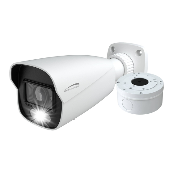
Summary of Contents for Speco O5LT1
- Page 1 User Manual Full-Color 5MP White Light Intensifier IP Camera O5LB1/O5LT1 Please read this manual carefully before operating the unit and keep it for further reference...
- Page 2 Important Safeguards and Warnings 1. Electrical safety All installation and operation here should conform to local electrical safety codes. Use a certified/listed 12VDC Class2 power supply only. Please note: Do not connect two power supplying sources to the device at the same time; it may result in device damage! The product must be grounded to reduce the risk of electric shock.
- Page 3 Statement This guide is for reference only. Product, manuals, and specifications may be modified without prior notice. Speco Technologies reserves the right to modify these without notice and without incurring any obligation. Speco Technologies is not liable for any loss caused by improper operation.
-
Page 4: Table Of Contents
Table of Contents Introduction ..........................................2 Web Access and Login ......................................3 Live View..........................................4 Camera Configuration ......................................6 System Configuration ................................6 4.1.1 System Information ..............................6 4.1.2 Date and Time ................................6 4.1.3 Local Recording ................................6 4.1.4 Storage .................................. - Page 5 4.7.1 Backup and Restore ..............................39 4.7.2 Reboot ..................................39 4.7.3 Upgrade ..................................39 4.7.4 Operation Log ................................40 Search ............................................ 41 Image Search ..................................41 Video Search ..................................43 5.2.1 Local Video Search ..............................43 5.2.2 SD Card Video Search..............................44 Appendix ............................................47 Appendix 1 Troubleshooting ......................................47 Appendix 2 Specifications .......................................
-
Page 6: Introduction
Thank you for purchasing this network camera! Please read this manual carefully before operating the unit and retain it for further reference. Should you require any technical assistance, please contact Speco Technologies Technical Support at 1-800-645-5516. Main Features Built-in PoE (Power over Ethernet) ... -
Page 7: Web Access And Login
2 Web Access and Login The IP camera settings can be accessed via a web browser through the LAN. Available web browser: IE (plug-in required)/ Firefox/Edge/Safari/Google Chrome It is recommended to use the latest version of these web browsers. The menu display and operation of the camera may be slightly different by using the browser with plug-in or without plug-in. Installing plug-in will display more functions of the camera. -
Page 8: Live View
3 Live View The window below will be shown after logging in. The following table describes the icons on the live view interface Icon Description Icon Description Original size of resolution SD card recording indicator Fit (correct scale) Abnormal color indicator Auto (fill the window) Abnormal clarity indicator Full screen (show video only) - Page 9 All indicator icons above will flash in live view interface only when the corresponding events are enabled. In full screen mode, to exit, double click on the mouse or press the ESC key on the keyboard. Click the zoom/focus control button to show the control panel. The descriptions of the control panel are as follows: Icon Description Icon...
-
Page 10: Camera Configuration
4 Camera Configuration Press the “Setup” button to go to the configuration interface. Note: Wherever applicable, click the “Save” button to save the settings. 4.1 System Configuration 4.1.1 System Information In the “System Information” interface, the system information of the device is listed. 4.1.2 Date and Time To set the time and date, go to SystemDate and Time. -
Page 11: Storage
Additionally, the snapshots triggered by smart events (including face detection, line crossing detection and intrusion detection) can be selected to save to the local PC. Rendering Mode: High-efficient mode, compatible mode or low-efficient mode can be optional. If the performance of your computer is not compatible with the web client or your computer has no graphics card, low-efficient mode is suggested. - Page 12 Weekly schedule Set the alarm time from Monday to Sunday for a single week. Each day is divided in one-hour increments. Green means scheduled. Blank means unscheduled. “Add”: Add the schedule for a special day. Drag the mouse to set the time on the timeline. “Erase”: Delete the schedule.
-
Page 13: Video Configuration
Set the format, resolution and quality of the image saved on the SD card and the snapshot interval and quantity and the timing snapshot here. Snapshot Quantity: The number you set here is the maximum quantity of snapshots. The actual quantity of snapshots may be less than this number. - Page 14 Brightness: Set the brightness level of the camera’s image. Contrast: Set the color difference between the brightest and darkest parts. Hue: Set the total color degree of the image. Saturation: Set the degree of color purity. The purer the color, the brighter the image is. Sharpness: Set the resolution level of the image plane and the sharpness level of the image edge.
-
Page 15: Video / Audio Configuration
value) according to the actual situation. If “Manual” is selected, the gain value shall be set manually. The higher the value is, the brighter the image is. Frequency: 50Hz and 60Hz can be optional. Overexposure Control: Choose “OFF”, “Low”, “Mid” or “High”. This function can automatically adjust the exposure parameter according to the actual effect of the image, effectively avoiding detail missing caused by image overexposure, so that the image will be more vivid. -
Page 16: Osd Configuration
Three video streams can be adjustable. Resolution: The size of image. Frame rate: The higher the frame rate, the video is smoother. Bitrate type: CBR and VBR are optional. Bitrate is related to image quality. CBR means that no matter how much change is seen in the video scene, the compression bitrate will be kept constant. -
Page 17: Video Mask
Set time stamp, device name, OSD content and picture overlap here. After enabling the corresponding display and entering the content, drag them to change their position. Then click the “Save” button to save the settings. Picture Overlap Settings: Check “OSD Content1”, choose “Picture Overlay” and click “Browse” to select the overlap picture. Then click “Upload” to upload the overlap picture. -
Page 18: Event Setup
1. Check “Enable” and then click the “Draw Area” button. 2. Drag the mouse to set the ROI area. 3. Set the level. 4. Click the “Save” button to save the settings. 4.3 Event Setup 4.3.1 Motion Detection Go to AlarmMotion Detection to set motion detection alarm. 1. -
Page 19: Other Alarms
motion-based recording to the NVR or CMS, even if there is motion in the video. Trigger SD Snap: If selected, the system will capture images on motion detection and save the images on an SD card. Trigger SD Recording: If selected, video will be recorded on an SD card on motion detection. Trigger Email: If “Trigger Email”... -
Page 20: Alarm Server
1. Go to AlarmAnomalySD Card Error as shown below. 2. Click “Enable” and set the alarm holding time. 3. Set alarm trigger options. Trigger alarm out, Email and FTP. The setup steps are the same as motion detection. Please refer to motion detectionchapter for details. -
Page 21: Line Crossing
1. Enable the applicable detection that is desired. Scene Change Detection: Alarms will be triggered if the scene of the video has changed. Video Blur Detection: Alarms will be triggered if the video becomes blurry. Video Cast Detection: Alarms will be triggered if the video becomes obscured. 2. - Page 22 1. Enable line crossing alarm and select the snapshot type and the detection target. Save Panoramic Picture to SD Card: If it is enabled, the detected panoramic pictures will be captured and saved to the SD card when there are targets detected. Save Target Cutout to SD Card: If it is enabled, the detected target cutout pictures will be captured and saved to the SD card when there are targets detected.
-
Page 23: Intrusion
Set the alarm line number and direction. Up to 4 lines can be added. Multiple lines cannot be added simultaneously. Direction:A<->B, A->B and A<-B optional. This indicates the direction of the intruder who crosses over the alarm line that would trigger the alarm. - Page 24 1. Enable intrusion alarm and select the snapshot type and the detection target. 2. Set the alarm holding time. 3. Click the “Save” button to save the settings. 4. Set the alarm area of the intrusion detection. Click the “Area” tab to go to the interface as shown below. Set the alarm area number on the right side.
-
Page 25: Face Detection
3. Cameras should be mounted at a height of 10ft or above. 4. Keep the mounting angle of the camera at about 45°. 5. The detected objects should not be less than 1% of the entire image and the largest sizes of the detected objects should not be more than 1/8 of the entire image. - Page 26 Use this to draw the approximate size of the face that you want the camera to capture. This is useful when there are multiple faces in the background or foreground that are not needed to be captured. To enable, Click “Draw Area” and drag the border lines of the rectangle to modify its size.
-
Page 27: Region Entrance
3. The depression angle (a) of the camera shall be less than or equal to 15°. 4. The object distance depends on the focal-length of the lens mounted in the camera. 5. In order to guarantee the captured face recognition rate, the requirement for face capture are: left or right face turn angle is less than about 30°;... -
Page 28: Region Exiting
Set the alarm area number on the right side. Up to 4 alarm areas can be added. Click the “Draw Area” button and then click around the area where you want to set as the alarm area in the image on the left side (the alarm area should be a closed area). -
Page 29: Target Counting
Set the alarm area number on the right side. Up to 4 alarm areas can be added. Click the “Draw Area” button and then click around the area where you want to set as the alarm area in the image on the left side (the alarm area should be a closed area). - Page 30 Staying Threshold: When the targets (human/vehicle) staying in the specified area exceed the threshold, alarms will be triggered. Counting Reset: The current number of the target counting can be reset. You can choose to reset the counting daily, weekly or monthly.
- Page 31 6. View the statistical information of target counting by line. Click “Chart” to enter the following interface. Select the report type. Daily report, weekly report, monthly report and annual report are selectable. Select the count type. Enter or leave can be optional. Select the start time and then click “Count”.
-
Page 32: Network Configuration
4.5 Network Configuration 4.5.1 TCP/IP Go to NetworkTCP/IP interface as shown below. There are two ways for network connection. Use IP address (take IPv4 for example)-obtain a local IP address automatically through DHCP. A typical router has a DHCP server built in, and therefore is able to assign an IP address to the camera. -
Page 33: Port
Either method of network connection can be used. If PPPoE is used to connect internet, the camera will get a dynamic WAN IP address. This IP address will change frequently. To be notified, the IP change notification function can be used. Click “IP Change Notification Config”... -
Page 34: Onvif
1. Check “Enable”. 2. Check the IP address and port of the transfer media server in the VMS. Then enable the auto report in the VMS when adding a new device. Next, enter the remaining information of the device in the VMS. After that, the system will automatically allot a device ID. -
Page 35: Snmp
4.5.6 SNMP To get camera status, parameters and alarm information and remotely manage the camera, the SNMP function can be used. Before using SNMP, please install an SNMP management tool and set the parameters of the SNMP, such as SNMP port, trap address. 1. -
Page 36: 802.1X
4.5.7 802.1x If it is enabled, the camera’s data can be protected. When the camera is connected to the network protected by the IEE802.1x, user authentication is needed. To use this function, the camera shall be connected to a switch supporting 802.1x protocol. The switch can be reckoned as an authentication system to identify the device in a local network. -
Page 37: Rtmp
4.5.9 RTMP You can access the third-party (like YouTube) to realize video live view through RTMP protocol. Go to ConfigNetworkRTMP. Check “Enable”, select stream type, set the reconnection time after timeout and server address as needed. Server address: Enter the server address allocated by the third party server. After that, click “Save”... -
Page 38: Ftp
Select the secure connection type at the “Secure Connection” pull-down list according to what’s required. SMTP Port: The SMTP port. Send Interval(S): The time interval of sending email. For example, if it is set to 60 seconds and multiple motion detection alarms are triggered within 60 seconds, they will be considered as only one alarm event and only one email will be sent. -
Page 39: Qos
the following interface will be displayed. * If there is a signed certificate, click “Browse” to select it and then click “Install” to install it. * Click “Create a private certificate” to enter the following creation interface. Click the “Create” button to create a private certificate. Enter the country (only two letters available), domain (camera’s IP address/domain), validity date, password, province/state, region and so on. -
Page 40: Security Configuration
Manager DSCP: The range is from 0 to 63. Generally speaking, the larger the number is, the higher the priority is. 4.6 Security Configuration 4.6.1 User Admin Go to SecurityUser Admin interface as shown below. Add user: 1. Click “Add” to pop up the following textbox. 2. -
Page 41: Online User
3. Enter the old password of the user in the “Old Password” text box. 4. Enter the new password in the “New password” and “Confirm Password” text box. 5. Modify the permission as necessary. 6. Click the “OK” button to save the settings. Note: To change the access level of a user, the user must be deleted and added again with the new access level. -
Page 42: Security Management
The setup steps are as follows: Check the “Enable address filtering” check box. Select “Block/Allow the following address”, IPv4/IPv6 and then enter IP address in the address box and click the “Add” button. 4.6.4 Security Management Go to SecuritySecurity Management as shown below. In order to prevent against malicious password unlocking, “locking once illegal login”... -
Page 43: Maintenance Configuration
4.7 Maintenance Configuration 4.7.1 Backup and Restore Go to MaintenanceBackup & Restore. Import & Export Settings Configuration settings of the camera can be exported form a camera into another camera. 1. Click “Browse” to select the save path for import or export information on the PC. 2. -
Page 44: Operation Log
4.7.4 Operation Log To query and export log: 1. Go to MaintenanceOperation Log. 2. Select the main type, sub type, start and end time. 3. Click “Search” to view the operation log. 4. Click “Export” to export the operation log. -
Page 45: Search
5 Search 5.1 Image Search In the Setup interface, click Search to go to the interface as shown below. Images that are saved on the PC or SD card can be found here. Local Image Search 1. Choose “Picture”—“Local”. 2. - Page 46 Click to return to the previous interface. SD Card Image Search 1. Choose “Picture”—“SD Card”. 2. Set time: Select date and choose the start and end time. 3. Choose the alarm events at the bottom of the interface. 4. Click to search the images.
-
Page 47: Video Search
Icon Description Icon Description Close: Select an image and click Close all: Click this button to close all this button to close the image. images. Save: Click this button to select the Save all: Click this button to select the path for saving the image on the path for saving all pictures on the PC. -
Page 48: Sd Card Video Search
Icon Description Icon Description Play button. After pausing the video, Pause button click this button to continue playing. Stop button Speed down Speed up Watermark display Enable / disable audio; drag the slider to adjust the volume after enabling audio. 5.2.2 SD Card Video Search Click Search to go to the interface as shown below. - Page 49 4. Select the alarm events at the bottom of the interface. 5. Select mix stream (video and audio stream) or video stream as needed. 6. Double click on a file name in the list to start playback. The time table can be shown in 24H/12H/2H/1H format by clicking the corresponding buttons. Video clip and downloading 1.
- Page 50 Click “Set up” to set the storage directory of the video files. Click “Open” to play the video. Click “Clear List” to clear the downloading list. Click “Close” to close the downloading window.
-
Page 51: Appendix
Appendix Appendix 1 Troubleshooting IP Scanner does not show any device. Make sure that the PC that’s running IP Scanner is on the same local network as the devices. Internet Explorer cannot download ActiveX control. IE browser may be set up to block ActiveX. Follow the steps below. 1. -
Page 52: Appendix 2 Specifications
Interfaces Reset Storage Built-in micro SD card slot; up to 256GB Remote Web browser, SecureGuard CMS/VMS, Apple TV, Amazon Fire TV, Speco Blue Monitoring Online Support simultaneous monitoring for up to 10 users and multi-stream transmission Connection UDP, IPv4, IPv6, DHCP, NTP, RTSP, RTP, RTCP, PPPoE, DDNS, SMTP, FTP, SNMP,HTTP, 802.1x, UPnP,... - Page 53 1CH audio input; Built-in MIC×1 Interfaces Reset Storage Built-in micro SD card slot; up to 256GB Remote Web browser, SecureGuard CMS/VMS, Apple TV, Amazon Fire TV, Speco Blue Monitoring Online Support simultaneous monitoring for up to 10 users and multi-stream transmission Connection Network Protocol UDP, IPv4, IPv6, DHCP, NTP, RTSP, RTP, RTCP, PPPoE, DDNS, SMTP, FTP, SNMP,HTTP, 802.1x, UPnP, HTTPs, QoS...
- Page 54 Models: O5LB1/O5LT1 Federal Communications Commission (FCC) Statements This device complies with Part 15 of the FCC Rules. Operation is subject to the following two conditions: (1) This device may not cause harmful interference, and (2) This device must accept any interference received, including interference that may cause undesired operation.
Need help?
Do you have a question about the O5LT1 and is the answer not in the manual?
Questions and answers