Table of Contents
Advertisement
Quick Links
DI-000-IPF01-02B
WARNINGS AND CAUTIONS:
• To be installed and/or used in accordance with appropriate electrical codes and regulations.
• If you are unsure about any part of these instructions, consult a qualified electrician.
• To avoid overheating and possible damage to this device and other equipment, do not install to
control a receptacle, fluorescent lighting, a motor- or a transformer-operated appliance other than
appropriate ceiling fans.
• To reduce the risk of fire or electrical shock, this control is to be used with ceiling fans that are rated
120VAC, total load 1.5 amperes maximum.
Tools needed to install your Fan Speed Control:
Slotted/Philips Screwdriver
Electrical Tape
Pliers
Pencil
Cutters
Ruler
Changing the color of your Fan Speed Control:
Your Fan Speed Control includes two color options. The Control ships with
the White frame attached. To change color of frame, proceed as follows:
Push in side at tab
to release
Position the Slide Switch Shaft with the opening in the frame and line
up the plastic snaps with the square holes in the strap..
Installing Fan Speed Control by itself or with other
devices:
If installing Control in a single device application, proceed with the
INSTALLING YOUR FAN SPEED CONTROL section. If installing
Control in a multi-device application, proceed as follows:
MULTI-DEVICE APPLICATION:
NOTE: You only need to remove side sections if installing with other
controls or if it does not fit in wall box – not when installing with
mechanical switches.
NOTE: There is NO derating necessary for multi-gang installations of
this Fan Speed Control.
Single Pole (One location) or 3-Way (Multi-location)
Bend back and
forth to remove side
section
INSTALLING YOUR FAN SPEED CONTROL
NOTE: Use check boxes
Step 1
Line up tabs on back of
slider to switch shaft and
OFF
press in side to attach
OFF
OFF
OFF
OFF
OFF
Step 2
Step 3
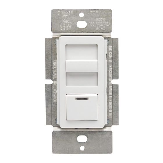
Quiet Fan Speed Control
120VAC, 60Hz
Cat. No. IPFØ1-1L, 1.5A (Lighted)
INSTALLATION INSTRUCTIONS
WARNINGS AND CAUTIONS:
• For use on ceiling paddle fans with split-capacitor or shaded pole motors only. Please refer to
manufacture's instructions or rating label on the motor to confirm type. Use with any other types of
motors or equipment may cause overheating and/or damge to the motors or equipment.
• Use only one (1) Fan Speed Control per load. The switch(es) will turn ON the fan at the speed level
selected at the control.
• Disconnect power at circuit breaker or fuse when servicing fixture.
• Use this device only with copper or copper clad wire. With aluminum wire use only devices marked
CO/ALR or CU/AL.
Remove
all inner
side
sections
Do not
remove
outer
side
sections
√
when Steps are completed.
WARNING:
To avoid fire, shock, or death; TURN OFF
POWER at circuit breaker or fuse and test that power is off
before wiring!
ON
OFF
ON
ON
OFF
ON
ON
OFF
ON
ON
OFF
ON
ON
OFF
ON
ON
OFF
ON
Removing existing switch:
Remove existing
wallplate and switch mounting screws. Carefully pull switch
from wall box. DO NOT remove wires attached to the switch
at this time.
Identifying your wiring application (most
common):
NOTE: If the wiring in the wall box does not resemble any of
these configurations, consult a qualified electrician.
Step 3
con't
Single-Pole:
3-Way:
Look at the back of your switch.
Look at the back of your switch.
If there are 2 wires connected to
If there are 3 wires connected to
two screw terminals (not
three screw terminals (not including
including a green or bare copper
a green or bare copper wire used
wire used for grounding), you
for grounding), you have a 3-Way
have a Single-Pole switch.
switch. Note that one of the
screw terminals will usually be a
different color (black) or labeled
Common. Tag that wire with
electrical tape to identify.
Disconnecting switch wires and preparing wires:
Step 4
• Disconnect wires from screw terminals or
Quickwire™ slots (shown).
• Pull off pre-cut insulation from Control leads.
• Make sure that the ends of the wires from the
wall box are straight (cut if necessary) .
• Remove 5/8" (1.6 cm) of insulation from each
wire in the wall box (shown).
• For Single-Pole Application, go to Step 5A.
• For 3-Way Application, go to Step 5B.
(if necessary)
Press in slot and
pull out wire
Tag Common
Screw Wire
Strip 5/8"
5/8"
Cut
Strip Gage
Advertisement
Table of Contents

Related Manuals for Leviton DECORA ILLUMATECH IPF01-1LX


Summary of Contents for Leviton DECORA ILLUMATECH IPF01-1LX
- Page 1 Single Pole (One location) or 3-Way (Multi-location) Quiet Fan Speed Control 120VAC, 60Hz Cat. No. IPFØ1-1L, 1.5A (Lighted) DI-000-IPF01-02B INSTALLATION INSTRUCTIONS WARNINGS AND CAUTIONS: WARNINGS AND CAUTIONS: • For use on ceiling paddle fans with split-capacitor or shaded pole motors only. Please refer to •...
- Page 2 Leviton is not liable for incidental, indirect, special, or consequential damages, including without limitation, damage...
Need help?
Do you have a question about the DECORA ILLUMATECH IPF01-1LX and is the answer not in the manual?
Questions and answers