Table of Contents
Advertisement
Quick Links
Advertisement
Table of Contents

Related Manuals for Dell VTY3T


Summary of Contents for Dell VTY3T
- Page 1 Questo manuale d’istruzione è fornito da trovaprezzi.it. Scopri tutte le offerte per Dell PowerEdge T440 VTY3T o cerca il tuo prodotto tra le migliori offerte di Server Dell EMC PowerEdge T440 Regulatory Model: E30S Series Regulatory Type: E30S002...
- Page 2 A WARNING indicates a potential for property damage, personal injury, or death. Copyright © 2018 Dell Inc. or its subsidiaries. All rights reserved. Dell, EMC, and other trademarks are trademarks of Dell Inc. or its subsidiaries. Other trademarks may be trademarks of their respective owners.
-
Page 3: Table Of Contents
Contents 1 Dell EMC PowerEdge T440 overview......................8 Supported configurations for the PowerEdge T440 system..................8 Front view of the system..............................10 Status LED indicators..............................14 System health and system ID indicator codes......................16 Drive indicator codes..............................17 Back view of the system..............................18 NIC indicator codes.............................. - Page 4 Viewing System Setup.............................. 36 System Setup details..............................36 System BIOS................................37 iDRAC Settings utility..............................57 Device Settings................................57 Dell Lifecycle Controller..............................57 Embedded system management..........................57 Boot Manager.................................. 58 Viewing Boot Manager..............................58 Boot Manager main menu............................58 One-shot BIOS boot menu............................58 System Utilities................................59...
- Page 5 Removing the drive from the drive carrier......................74 Installing a drive into the drive carrier........................75 Removing a 2.5 inch drive from a 3.5 inch drive adapter..................76 Installing a 2.5 inch drive into a 3.5 inch drive adapter..................77 Removing a 3.5 inch drive adapter from a 3.5 inch drive carrier................78 Installing a 3.5 inch drive adapter into the 3.5 inch drive carrier................
- Page 6 7 Using system diagnostics........................... 143 Dell Embedded System Diagnostics..........................143 Running the Embedded System Diagnostics from Boot Manager..............143 Running the Embedded System Diagnostics from the Dell Lifecycle Controller..........143 System diagnostic controls............................. 144 8 Jumpers and connectors ........................... 145 Jumpers and connectors ..............................145 System board jumper settings..........................
- Page 7 9 Getting help............................... 149 Contacting Dell................................149 Accessing system information by using QRL......................149 Quick Resource Locator for T440.......................... 150 Receiving automated support with SupportAssist ....................150 Installation and Service Manual Contents...
-
Page 8: Dell Emc Poweredge T440 Overview
• Back view of the system • Locating the Service Tag of your system Supported configurations for the PowerEdge T440 system The Dell EMC PowerEdge T440 system supports the following configurations: Installation and Service Manual Dell EMC PowerEdge T440 overview... - Page 9 Figure 1. Supported configurations for a PowerEdge T440 system Installation and Service Manual Dell EMC PowerEdge T440 overview...
-
Page 10: Front View Of The System
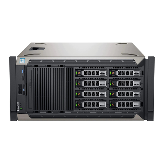
Front view of the system The front panel view of the systems. Figure 2. Front panel view of a 4 x 3.5 inch cabled drive system Installation and Service Manual Dell EMC PowerEdge T440 overview... - Page 11 Figure 3. Front panel view of a 8 x 3.5-inch hot swappable drive system Installation and Service Manual Dell EMC PowerEdge T440 overview...
- Page 12 Figure 4. Front panel view of a 8 x 3.5-inch hot swappable drive system in rack mode Installation and Service Manual Dell EMC PowerEdge T440 overview...
- Page 13 System identification The System Identification (ID) button is available on the front and back of the systems. Press the button to identify a system in a rack by turning on the button Installation and Service Manual Dell EMC PowerEdge T440 overview...
-
Page 14: Status Led Indicators
Enables you to convert the tower system to a rack system. Related links Status LED indicators Technical specifications Status LED indicators NOTE: The indicators display solid amber if any error occurs. Figure 6. Status LED indicators Installation and Service Manual Dell EMC PowerEdge T440 overview... - Page 15 Check the System Event Log or system messages for the specific issue. For more information about error • When the system is turned on. messages, see the Dell Event and Error Messages • When the system is in standby. Reference Guide at Dell.com/openmanagemanuals >...
-
Page 16: System Health And System Id Indicator Codes
Blinking amber Indicates that the system is experiencing a fault. Check the System Event Log for specific error messages. For more information about error messages, see the Dell Event and Error Messages Reference Guide at Dell.com/openmanagemanuals > OpenManage software. Related links... -
Page 17: Drive Indicator Codes
Flashes amber four times per second Drive failed. Flashes green slowly Drive rebuilding. Solid green Drive online. Flashes green for three seconds, amber for three seconds, and Rebuild stopped. then turns off after six seconds Installation and Service Manual Dell EMC PowerEdge T440 overview... -
Page 18: Back View Of The System
For more information about the PSU configurations, see the Technical Specifications section Enables you to remotely access iDRAC. For more information, see the iDRAC9 Enterprise port iDRAC User’s Guide at Dell.com/idracmanuals. Installation and Service Manual Dell EMC PowerEdge T440 overview... -
Page 19: Nic Indicator Codes
NIC, and the link LED indicator indicates the speed of the connected network. Figure 10. NIC indicator codes link LED indicator activity LED indicator Installation and Service Manual Dell EMC PowerEdge T440 overview... -
Page 20: Power Supply Unit Indicator Codes
Blinking green and turns off When hot-plugging a PSU, the PSU handle blinks green five times at a rate of 4 Hz and turns off. This indicates a PSU mismatch with respect to efficiency, feature set, health status, or supported voltage. Installation and Service Manual Dell EMC PowerEdge T440 overview... -
Page 21: Locating The Service Tag Of Your System
Express Service Code and Service Tag. Alternatively, the information may be on a sticker on the chassis of the system. The mini Enterprise Service Tag (EST) is found on the back of the system. This information is used by Dell to route support calls to the appropriate personnel. -
Page 22: Documentation Resources
Managing your system For information about systems management Dell.com/openmanagemanuals software offered by Dell, see the Dell OpenManage Systems Management Overview Guide. For information about setting up, using, and Dell.com/openmanagemanuals troubleshooting OpenManage, see the Dell OpenManage Server Administrator User’s Guide. - Page 23 Working with the Dell For information about understanding the features Dell.com/storagecontrollermanuals PowerEdge RAID controllers of the Dell PowerEdge RAID controllers (PERC), Software RAID controllers, or BOSS card and deploying the cards, see the Storage controller documentation. Understanding event and error For information about checking the event and error Dell.com/openmanagemanuals...
-
Page 24: Technical Specifications
Technical specifications The technical and environmental specifications of your system are outlined in this section. Topics: • System dimensions • Chassis weight • Processor specifications • PSU specifications • System battery specifications • Expansion bus specifications • Memory specifications • Storage controller specifications •... -
Page 25: System Dimensions
System dimensions Figure 12. Details the dimensions of the PowerEdge T440 system Table 9. Dimensions of PowerEdge T440 system (with bezel) 218 mm (8.58 307.9 mm 430.3 mm 464.362 mm 471.333 mm 538.4 mm 573.636 mm 37.065 mm (12.12 in) (16.94 in) (18.28 in) (17.37 in) -
Page 26: Chassis Weight
Chassis weight Table 10. Chassis weight System configuration Maximum weight 4 x 3.5 inch drive system 23.9 Kg (52.69 lb) 8 x 3.5 inch drive system 29.5 Kg (65.03 lb) 16 x 2.5 inch drive system 27.7 Kg (61.06 lb) Processor specifications The PowerEdge T440 system supports up to two Intel Xeon Processor Scalable Family processors. -
Page 27: Storage Controller Specifications
Table 12. Memory specifications Memory module sockets Memory capacity Minimum RAM Maximum RAM Sixteen 288-pin 8 GB with dual processors • 8 GB, 16 GB, or 32 GB single • Up to 512 GB RDIMM (minimum one memory module rank or dual rank (RDIMMs) •... -
Page 28: Nic Ports
IDSDM The IDSDM/vFlash card sits in the back of the system, in a Dell-proprietary slot. IDSDM/vFlash card supports three micro SD cards (two cards for IDSDM and one card for vFlash). MicroSD cards capacity for IDSDM are 16/32/64 GB while for vFlash the microSD card capacity is 16 GB. -
Page 29: Environmental Specifications
Environmental specifications NOTE: For additional information about environmental measurements for specific system configurations, see Dell.com/ environmental_datasheets. Table 15. Temperature specifications Temperature Specifications Storage –40°C to 65°C (–40°F to 149°F) Continuous operation (for altitude less than 950 m or 3117 10°C to 35°C (50°F to 95°F) with no direct sunlight on the equipment. -
Page 30: Standard Operating Temperature
Table 20. Operating temperature de-rating specifications Operating temperature de-rating Specifications Up to 35°C (95°F) Maximum temperature is reduced by 1°C/300 m (1°F/547 ft) above 950 m (3,117 ft). 35°C to 40°C (95°F to 104°F) Maximum temperature is reduced by 1°C/175 m (1°F/319 ft) above 950 m (3,117 ft). -
Page 31: Particulate And Gaseous Contamination Specifications
Two non-redundant power supply units are required. • Two non-redundant system fans are required. • Non-Dell qualified peripheral cards and/or peripheral cards greater than 25 W are not supported. • GPU is not supported. • Tape backup unit is not supported. -
Page 32: Initial System Setup And Configuration
The Integrated Dell Remote Access Controller (iDRAC) is designed to make system administrators more productive and improve the overall availability of Dell systems. iDRAC alerts administrators to system issues, helps them perform remote system management, and reduces the need for physical access to the system. -
Page 33: Log In To Idrac
Ensure that you change the default user name and password after setting up the iDRAC IP address. For more information about logging in to the iDRAC and iDRAC licenses, see the latest Integrated Dell Remote Access Controller User's Guide at Dell.com/idracmanuals. -
Page 34: Downloading Drivers And Firmware
Using Dell OpenManage Deployment Toolkit (DTK) Dell.com/openmanagemanuals Downloading drivers and firmware Dell recommends that you download and install the latest BIOS, drivers, and systems management firmware on your system. Prerequisite Ensure that you clear the web browser cache before downloading the drivers and firmware. -
Page 35: Pre-Operating System Management Applications
You can manage basic settings and features of a system without booting to the operating system by using the system firmware. Topics: • Options to manage the pre-operating system applications • System Setup • Dell Lifecycle Controller • Boot Manager • PXE boot Options to manage the pre-operating system applications Your system has the following options to manage the pre-operating system applications: •... -
Page 36: Viewing System Setup
The iDRAC settings utility is an interface to set up and configure the iDRAC parameters by using UEFI (Unified Extensible Firmware Interface). You can enable or disable various iDRAC parameters by using the iDRAC settings utility. For more information about this utility, see Integrated Dell Remote Access Controller User’s Guide at Dell.com/idracmanuals. -
Page 37: System Bios
System BIOS You can use the System BIOS screen to edit specific functions such as boot order, system password, setup password, set the SATA and PCIe NVMe RAID mode, and enable or disable USB ports. Related links System BIOS Settings details System Information Memory Settings Processor Settings... - Page 38 Option Description Boot Settings Specifies options to specify the Boot mode (BIOS or UEFI). Enables you to modify UEFI and BIOS boot settings. Network Settings Specifies options to manage the UEFI network settings and boot protocols. Legacy network settings are managed from the Device Settings menu. Integrated Devices Specifies options to manage integrated device controllers and ports, specifies related features and options.
- Page 39 Option Description System Specifies the name of the system manufacturer. Manufacturer System Specifies the contact information of the system manufacturer. Manufacturer Contact Information System CPLD Specifies the current version of the system complex programmable logic device (CPLD) firmware. Version UEFI Compliance Specifies the UEFI compliance level of the system firmware.
- Page 40 Option Description Memory Operating Specifies the memory operating mode. The options available are Optimizer Mode, Single Rank Spare Mode, Multi Mode Rank Spare Mode, and Mirror Mode. This option is set to Optimizer Mode by default. NOTE: The Memory Operating Mode option can have different default and available options based on the memory configuration of your system.
- Page 41 Option Description The options available are Maximum data rate, 10.4 GT/s, and 9.6 GT/s. This option is set to Maximum data rate by default. Maximum data rate indicates that the BIOS runs the communication links at the maximum frequency supported by the processors.
- Page 42 Option Description Option Description Family-Model- Specifies the family, model, and stepping of the processor as defined by Intel. Stepping Brand Specifies the brand name. Level 2 Cache Specifies the total L2 cache. Level 3 Cache Specifies the total L3 cache. Number of Cores Specifies the number of cores per processor.
- Page 43 Option Description Option Description Capacity Specifies the total capacity of the drive. This field is undefined for removable media devices such as optical drives. Boot Settings You can use the Boot Settings screen to set the boot mode to either BIOS or UEFI. It also enables you to specify the boot order. •...
- Page 44 Operating systems must be UEFI-compatible to be installed from the UEFI boot mode. DOS and 32-bit operating systems do not support UEFI and can only be installed from the BIOS boot mode. NOTE: For the latest information about supported operating systems, go to Dell.com/ossupport. Changing boot order About this task You may have to change the boot order if you want to boot from a USB key.
- Page 45 Network Settings You can use the Network Settings screen to modify UEFI PXE, iSCSI, and HTTP boot settings. The network settings option is available only in the UEFI mode. NOTE: The BIOS does not control network settings in the BIOS mode. For the BIOS boot mode, the optional Boot ROM of the network controllers handles the network settings.
- Page 46 UEFI iSCSI Settings You can use the iSCSI Settings screen to modify iSCSI device settings. The iSCSI Settings option is available only in the UEFI boot mode. BIOS does not control network settings in the BIOS boot mode. For the BIOS boot mode, the option ROM of the network controller handles the network settings.
- Page 47 On the System BIOS screen, click Integrated Devices. Integrated Devices details The Integrated Devices screen details are explained as follows: Option Description User Accessible Configures the user accessible USB ports. Selecting Only Back Ports On disables the front USB ports; selecting USB Ports All Ports Off disables all front and back USB ports.
- Page 48 Option Description Internal SD Primary When Redundancy is set to Disabled, either one of the SDMicroSD card can be selected to present itself as mass Card storage device by setting it to be primary card. By default primary SDMicroSD card is selected to be SD Card 1. If SD Card 1 is not present, then the controller will select SD Card 2 to be the primary SDMicroSD card.
- Page 49 Option Description Option Description x16 or x4 or x8 or x4x4x8 or x8x4x4 Bifurcation Slot 3 Bifurcation x4 or x8 Bifurcation Slot 4 Bifurcation Slot 5 Bifurcation x4 or x8 Bifurcation Serial Communication You can use the Serial Communication screen to view the properties of the serial communication port. Viewing Serial Communication To view the Serial Communication screen, perform the following steps: Turn on, or restart your system.
- Page 50 You can only change the rest of the options if the mode is set to Custom.This option is set to Performance Per Watt Optimized (DAPC) by default. DAPC is Dell Active Power Controller.Other options include Performance Per Watt (OS), Performance, and Workstation Performance.
- Page 51 Option Description Write Data CRC Enables or disables the Write Data CRC. This option is set to Disabled by default. Collaborative CPU Enables or disables the CPU power management option. When set to Enabled, the CPU power management is Performance controlled by the OS DBPM and the System DBPM (DAPC).
- Page 52 NOTE: If your operating system begins to load before you press F2, wait for the system to finish booting, and then restart your system and try again. On the System Setup Main Menu screen, click System BIOS. On the System BIOS screen, click System Security. System Security Settings details The System Security Settings screen details are explained as follows: Option...
- Page 53 Option Description NOTE: BIOS update requires HECI devices to be operational and DUP updates require IPMI interface to be operational. This setting needs to be set to Enabled to avoid updating errors. Secure Boot Enables Secure Boot, where the BIOS authenticates each pre-boot image by using the certificates in the Secure Boot Policy.
- Page 54 Steps To enter System Setup, press F2 immediately after turning on or rebooting your system. On the System Setup Main Menu screen, click System BIOS > System Security. On the System Security screen, verify that Password Status is set to Unlocked. In the System Password field, type your system password, and press Enter or Tab.
- Page 55 Press Esc to return to the System BIOS screen. Press Esc again, and a message prompts you to save the changes. Select Setup Password, change, or delete the existing setup password and press Enter or Tab. NOTE: If you change the system password or setup password, a message prompts you to reenter the new password. If you delete the system password or setup password, a message prompts you to confirm the deletion.
- Page 56 Option Description • SATA Ports in AHCI mode • BOSS PCIe Cards (Internal M.2 Drives) • Internal USB NOTE: RAID configurations and NVMe cards not are included as BIOS does not have the ability to distinguish between individual drives in those configurations. Redundant OS NOTE: This option is disabled if Redundant OS Location is set to None.
-
Page 57: Idrac Settings Utility
Dell Lifecycle Controller Dell Lifecycle Controller (LC) provides advanced embedded systems management capabilities including system deployment, configuration, update, maintenance, and diagnosis. LC is delivered as part of the iDRAC out-of-band solution and Dell system embedded Unified Extensible Firmware Interface (UEFI) applications. -
Page 58: Boot Manager
Launch System Enables you to access System Setup. Setup Launch Lifecycle Exits the Boot Manager and invokes the Dell Lifecycle Controller program. Controller System Utilities Enables you to launch System Utilities menu such as System Diagnostics and UEFI shell. Related links... -
Page 59: System Utilities
System Utilities System Utilities contains the following utilities that can be launched: • Launch Diagnostics • BIOS Update File Explorer • Reboot System Related links Boot Manager PXE boot You can use the Preboot Execution Environment (PXE) option to boot and configure the networked systems, remotely. To access the PXE boot option, boot the system and then press F12 during POST instead of using standard Boot Sequence from BIOS Setup. -
Page 60: Installing And Removing System Components
Damage due to servicing that is not authorized by Dell is not covered by your warranty. Read and follow the safety instructions that are shipped with your product. -
Page 61: Optional Front Bezel
Optional front bezel The front bezel is attached to the front of the system to prevent unauthorized access to the system peripherals. The front bezel can be locked for additional security. Removing the front bezel Prerequisite Follow the safety guidelines listed in Safety instructions. -
Page 62: System Feet
Using the key lock the bezel. Figure 14. Installing the front bezel System feet The system feet provide stability to the system in the tower mode. Removing the system feet Prerequisites NOTE: It is recommended that you remove the system feet only when you are converting the system from the tower mode to the rack mode, or when you are replacing the system feet with the wheel assembly. -
Page 63: Installing The System Feet
Figure 15. Removing the system feet Next step If applicable, install the system feet or the caster wheel assembly. Related links Installing the system feet Installing caster wheels Installing the system feet Prerequisites CAUTION: Install the feet on a stand-alone tower system to provide stability to the system. An unstable system might tip over and cause injury to the user or damage to the system. -
Page 64: Caster Wheels - Optional
Figure 16. Installing the system feet Next steps Place the system upright on a flat, stable surface, and rotate the system feet outward. Follow the procedure listed in After working inside your system. Caster wheels – optional Caster wheels provide mobility to the system in the tower mode. The caster wheel assembly consists of: •... -
Page 65: Installing Caster Wheels
Figure 17. Removing caster wheels Next step Install the caster wheels or the system feet, as applicable. Related links Installing the system feet Installing caster wheels Installing caster wheels Prerequisites Follow the safety guidelines listed in Safety instructions. Place the system on its side on a flat, stable surface. If installed, remove the system feet. -
Page 66: System Cover
Figure 18. Installing caster wheels Next step Follow the procedure listed in After working inside your system. Related links Removing the system feet System cover System cover provides security for the entire system and also helps in maintaining proper air flow inside the system. Removing the system cover Prerequisites Follow the safety guidelines listed in... -
Page 67: Installing The System Cover
Figure 19. Removing the system cover Next step Install the system cover. Related links Removing the front bezel Installing the system cover Installing the system cover Prerequisite NOTE: Ensure that all internal cables are connected and placed out of the way and no tools or extra parts are left inside the system. -
Page 68: Air Shroud
Figure 20. Installing the system cover Next steps Place the system upright on its feet on a flat and stable surface. If removed, install the bezel. Reconnect the peripherals and connect the system to the electrical outlet. Turn on the system, including all attached peripherals. Related links Installing the front bezel Air shroud... -
Page 69: Installing The Air Shroud
NOTE: Systems with x16 hard-drive backplanes use a different air shroud. To ensure proper cooling, always install the air shroud provided with your system. Figure 21. Removing the air shroud Next step Install the air shroud. Related links Installing the air shroud Installing the air shroud Prerequisites Follow the safety guidelines listed in... -
Page 70: Drives
Figure 22. Installing the air shroud Next step Follow the procedure listed in After working inside your system. Drives Drives are supplied in hot swappable drive carriers that fit in the drive slots. CAUTION: Before attempting to remove or install a drive while the system is running, see the documentation for the storage controller card to ensure that the host adapter is configured correctly. -
Page 71: Installing A Drive Blank
Figure 23. Removing a drive blank Next steps Follow the procedure listed in After working inside your system. Install a drive or a drive blank. If applicable, replace the front bezel. Related links Removing the front bezel Installing a drive blank Installing a drive blank The procedure for installing 2.5 inch and 3.5 inch drive blanks is identical. -
Page 72: Removing A Drive Carrier
Figure 24. Installing a drive blank Next step If removed, install the front bezel. Related links Installing the front bezel Removing a drive carrier Prerequisites Follow the safety guidelines listed in Safety instructions. If applicable, remove the front bezel. Using the management software, prepare the drive for removal. If the drive is online, the green activity or fault indicator flashes while the drive is turning off. -
Page 73: Installing A Drive Carrier
Figure 25. Removing a drive carrier Next steps Follow the procedure listed in After working inside your system. Install a drive carrier. If you are not replacing the drive immediately, insert a drive blank in the empty drive slot to maintain proper system cooling. Related links Installing a drive carrier Installing a drive blank... -
Page 74: Removing The Drive From The Drive Carrier
Close the drive carrier release handle to lock the drive in place. Figure 26. Installing a drive carrier Next step If applicable, install the front bezel. Related links Removing a drive blank Installing the front bezel Removing the drive from the drive carrier Prerequisite Follow the safety guidelines listed in Safety... -
Page 75: Installing A Drive Into The Drive Carrier
Figure 27. Removing the drive from the drive carrier Next step If applicable, install the drive into the drive carrier. Related links Removing the front bezel Installing a drive into the drive carrier Installing a drive blank Installing a drive into the drive carrier Installing a drive into the drive carrier Prerequisites Follow the safety guidelines listed in... -
Page 76: Removing A 2.5 Inch Drive From A 3.5 Inch Drive Adapter
Figure 28. Installing a drive into the drive carrier Related links Removing a drive blank Installing the front bezel Removing a 2.5 inch drive from a 3.5 inch drive adapter Prerequisites Follow the safety guidelines listed in Safety instructions. Remove the 3.5 inch drive adapter from the 3.5 inch drive carrier. NOTE: A 2.5 inch drive is installed in a 3.5 inch drive adapter, which is then installed in the 3.5 inch drive carrier. -
Page 77: Installing A 2.5 Inch Drive Into A 3.5 Inch Drive Adapter
Figure 29. Removing 2.5 inch drive from a 3.5 inch drive adapter Next step Install a 2.5 inch drive into a 3.5 inch drive adapter. Related links Removing a 3.5 inch drive adapter from a 3.5 inch drive carrier Installing a 2.5 inch drive into a 3.5 inch drive adapter Installing a 2.5 inch drive into a 3.5 inch drive adapter Prerequisite Follow the safety guidelines listed in... -
Page 78: Removing A 3.5 Inch Drive Adapter From A 3.5 Inch Drive Carrier
Figure 30. Installing a 2.5 inch drive into a 3.5 inch drive adapter Removing a 3.5 inch drive adapter from a 3.5 inch drive carrier Prerequisites Follow the safety guidelines listed in Safety instructions. If installed, remove the front bezel. Remove the 3.5 inch drive carrier from the system. -
Page 79: Installing A 3.5 Inch Drive Adapter Into The 3.5 Inch Drive Carrier
Figure 31. Removing a 3.5 inch drive adapter from a 3.5 inch drive carrier Next step Install the 3.5 inch drive carrier or install the 3.5 inch drive adapter into the 3.5 inch drive carrier. Related links Installing a 3.5 inch drive adapter into the 3.5 inch drive carrier Installing a 3.5 inch drive adapter into the 3.5 inch drive carrier Prerequisites Follow the safety guidelines listed in... -
Page 80: Optical Drives And Tape Drives
Figure 32. Installing a 3.5 inch drive adapter into the 3.5 inch drive carrier Next steps Install the 3.5 inch drive carrier into the system. If removed, install the front bezel. Related links Installing a 2.5 inch drive into a 3.5 inch drive adapter Installing the front bezel Optical drives and tape drives Your system supports one of the following configurations:... -
Page 81: Installing The Optical Or Tape Drive Blank
Figure 33. Removing the optical drive or tape drive blank Next steps Install the drive blank, an optical drive, or a tape drive. If applicable, replace the front bezel. Related links Installing a drive blank Installing the optical drive cage or tape drive Removing the front bezel Installing the front bezel Installing the optical or tape drive blank... -
Page 82: Removing The Optical Drive Cage Or Tape Drive
Figure 34. Installing the optical or tape drive blank Next steps Follow the procedure listed in After working inside your system. If applicable, replace the front bezel. Removing the optical drive cage or tape drive Prerequisites NOTE: The procedure to remove the optical drive cage is identical to removing a tape drive. Follow the safety guidelines listed in Safety instructions. -
Page 83: Installing The Optical Drive Cage Or Tape Drive
Figure 35. Removing the optical drive cage or tape drive Next step Install the optical drive cage or tape drive. Related links Installing the optical drive cage or tape drive Installing the front bezel Removing the front bezel Installing the optical drive cage or tape drive Prerequisite NOTE: The procedure to install the optical drive cage is the same as installing the tape drive. -
Page 84: Cabled Drives
Damage due to servicing that is not authorized by Dell is not covered by your warranty. Read and follow the safety instructions that are shipped with your product. -
Page 85: Installing The Internal Hard Drive Bay
Figure 37. Removing the internal hard drive bay Next step Follow the procedure listed in After working inside your system. Installing the internal hard drive bay Prerequisites Follow the safety guidelines listed in Safety instructions. Follow the procedure listed in Before working inside your system. -
Page 86: Removing A Cabled Drive
Damage due to servicing that is not authorized by Dell is not covered by your warranty. Read and follow the safety instructions that are shipped with your product. -
Page 87: Installing A Cabled Drive
Figure 39. Removing a cabled drive Next steps Follow the procedure listed in After working inside your system. Install the internal drive bay into the chassis. If disconnected, reconnect the power and data cable(s) to the remaining drive(s) in the internal drive bay. Related links Removing the internal hard drive bay Installing the internal hard drive bay... -
Page 88: Drive Backplane
Figure 40. Installing a cabled drive Next steps Install the internal drive bay into the chassis. Follow the procedure listed in After working inside your system. Enter System Setup and ensure that the drive controller is enabled. Exit System Setup and restart the system. Install any software required for operating the drive as described in the documentation for the drive. - Page 89 Figure 41. x16 drive backplane backplane P4 power connector backplane power connector backplane power connector for optical and tape drives signal connector Mini SAS HD SAS_A0 Mini SAS HD SAS_B0 I2C Connector Installation and Service Manual Installing and removing system components...
-
Page 90: Removing A Hard Drive Backplane
Figure 42. x8 drive backplane ODD power connector backplane P4 power connector backplane sideband signal connector Mini SAS SAS_A0 Mini SAS SAS_B0 Removing a hard drive backplane Prerequisites CAUTION: To prevent damage to the drives and backplane, you must remove the hard drives from the system before removing the backplane. -
Page 91: Installing A Hard Drive Backplane
Figure 43. Removing a backplane Next step Install a hard drive backplane. Related links Removing a drive blank Removing the optical drive cage or tape drive Removing a cabled drive Removing the air shroud Removing the front bezel Installing a hard drive backplane Installing a hard drive backplane Prerequisites Follow the safety guidelines listed in... - Page 92 Figure 45. Installing a hard drive backplane Next steps Install the air shroud. Install the drives into their original slots. If applicable, install the bezel. Follow the procedure listed in After working inside your system. Related links Installing the internal cooling fan Installing the air shroud Installing a cabled drive Installing the optical drive cage or tape drive...
-
Page 93: Backplane Cable Routing
Backplane cable routing Cable routing - 8 x 3.5 inch drive backplane cable retention latch SAS A0 SAS B0 drive backplane Installation and Service Manual Installing and removing system components... - Page 94 Figure 46. Cable routing - 8 x 3.5 inch drive backplane with internal PERC cable retention latch SAS A0 SAS B0 internal PERC drive backplane Installation and Service Manual Installing and removing system components...
- Page 95 Figure 47. Cable routing -16 x 2.5 inch drive backplane with internal PERC cable retention latch SAS A0 SAS B0 internal PERC drive backplane Installation and Service Manual Installing and removing system components...
-
Page 96: System Memory
Figure 48. Cable routing - 4 x 3.5 inch cabled HDD cable retention latch signal cable cabled HDD System memory The system supports DDR4 registered DIMMs (RDIMMs). System memory holds the instructions that are executed by the processor. NOTE: MT/s indicates DIMM speed in MegaTransfers per second. Memory bus operating frequency can be 2666 MT/s, 2400 MT/s, or 2133 MT/s depending on the following factors: •... - Page 97 Figure 49. System memory view Table 30. Memory channels Proces Channel 0 Channel 1 Channel 2 Channel 3 Channel 4 Channel 5 Proces Slots A1 and A7 Slots A2 and A8 Slots A3 Slots A4 and A9 Slots A5 and A10 Slots A6 sor 1 Proces...
-
Page 98: General Memory Module Installation Guidelines
Table 31. Memory population DIMM Type DIMMs Populated/ Operating Frequency (in Maximum DIMM Rank/Channel Voltage Channel MT/s) RDIMM 2666, 2400, 2133, 1866 Dual rank or single rank 1.2 V 2666, 2400, 2133, 1866 Dual rank or single rank LRDIMM 2666, 2400, 2133, 1866 Quad rank 1.2 V 2666, 2400, 2133, 1866... - Page 99 Memory optimized (independent channel) mode This mode supports Single Device Data Correction (SDDC) only for memory modules that use x4 device width. It does not impose any specific slot population requirements. Memory sparing NOTE: To use memory sparing, this feature must be enabled in BIOS menu of System Setup. Table 32.
-
Page 100: Removing A Memory Module
Processor Configuration Memory population Memory population information Multi rank sparing population order 1, 2, 3, 4, 5, 6, 7, 8, 9, 10 Populate in this order, odd amount allowed. Requires three ranks or more per channel. Dual CPU (Populate Optimized (Independent channel) C1{1}, C2{1}, C1{2}, C2{2}, C1{3}, Odd amount of DIMM slots per CPU round robin starting... -
Page 101: Installing A Memory Module
Next steps Install the memory module. If you are removing the memory module permanently, install a memory module blank. The procedure to install a memory module blank is similar to that of the memory module. Related links Removing the air shroud Installing a memory module Installing a memory module Prerequisite... -
Page 102: Cooling Fans
Damage due to servicing that is not authorized by Dell is not covered by your warranty. Read and follow the safety instructions that are shipped with your product. -
Page 103: Installing The Internal Cooling Fan
Figure 52. Removing the internal cooling fan Next steps Follow the procedure listed in After working inside your system. Install the internal cooling fan. Related links Removing the air shroud Installing the internal cooling fan Installing the internal cooling fan Prerequisites Follow the safety guidelines listed in Safety... -
Page 104: Removing The External Cooling Fan
Damage due to servicing that is not authorized by Dell is not covered by your warranty. Read and follow the safety instructions that are shipped with your product. -
Page 105: Installing The External Cooling Fan
Damage due to servicing that is not authorized by Dell is not covered by your warranty. Read and follow the safety instructions that are shipped with your product. -
Page 106: Optional Internal Usb Memory Key
Figure 55. Installing the external cooling fan Next steps Install the air shroud. Follow the safety guidelines listed in Safety instructions. Related links Installing the air shroud Removing the air shroud Optional internal USB memory key An optional USB memory key installed inside your system can be used as a boot device, security key, or mass storage device. To boot from the USB memory key, configure the USB memory key with a boot image and then specify the USB memory key in the boot sequence in System Setup. -
Page 107: Expansion Card Holder
Damage due to servicing that is not authorized by Dell is not covered by your warranty. Read and follow the safety instructions that are shipped with your product. -
Page 108: Installing The Expansion Card Holder
Damage due to servicing that is not authorized by Dell is not covered by your warranty. Read and follow the safety instructions that are shipped with your product. - Page 109 Card Type Slot Priority Maximum Allowed GPGPU (NVIDIA) Card, Network(Broadcom/Intel) 1,2,4,5 NIC (Intel) 1,2,4,5 PERC9/ 9.14G (FXN) 4,5,2 RAID - PERC9+ (Internal) (Dell) 4,5,2 RAID - PERC10 (Internal) (Dell) 4,5,2 RAID - PERC10 (External)(Dell) 4,5,2 NIC(Broadcom) 4,5,2 Card, Network ((Broadcom/Intel/Emulex, 4,5,2 Qlogic) BOSS M.2 (SATA) (Dell)
-
Page 110: Gpu Card Installation Guidelines
GPU card installation guidelines Observe the following guidelines while installing a GPU card: • GPU are supported only in the Rack mode configuration. • GPU can be installed only on systems that have 1100 W or higher power supply units. •... -
Page 111: Installing An Expansion Card
Figure 58. Removing an expansion card Figure 59. Installing the filler bracket Next steps Follow the procedure listed in After working inside your system. Install an expansion card. Install the expansion card holder. Install the air shroud. Related links Removing the air shroud Removing the expansion card holder Installing an expansion card Installing the expansion card holder... - Page 112 Remove the expansion card holder. Steps Unpack the expansion card and prepare it for installation. For instructions, see the documentation accompanying the card. Open the expansion card latch adjacent to the slot you want to install the expansion card. Remove the existing expansion card or filler bracket from the expansion card holder. NOTE: Store this bracket for future use.
-
Page 113: Optional Idsdm Or Vflash Card
Related links Removing the air shroud Removing a expansion card Installing the expansion card holder Optional IDSDM or vFlash card The IDSDM/vFlash card combines the IDSDM and/or vFlash features into a single module. NOTE: The write-protect switch is on the IDSDM/vFlash card. Removing the MicroSD card Prerequisites Follow the safety guidelines listed in... -
Page 114: Removing The Optional Idsdm Or Vflash Card
Removing the optional IDSDM or vFlash card Prerequisites Follow the safety guidelines listed in Safety instructions. Follow the procedure listed in Before working inside your system. Remove the air shroud. Steps Locate the IDSDM/vFlash connector on the system board. To locate IDSDM/vFlash, see the System board jumpers and connectors section. Holding the pull tab, lift the IDSDM/vFlash card out of the system. -
Page 115: Processors And Heat Sinks
Steps Locate the IDSDM/vFlash connector on the system board. To locate IDSDM/vFlash, see the System board jumpers and connectors section. Align IDSDM/vFlash card with the connector on the system board. Push IDSDM/vFlash card until it is firmly seated on the system board. Figure 63. -
Page 116: Removing A Processor And Heat Sink Module
Removing a processor and heat sink module Prerequisites WARNING: The heat sink may be hot to touch for some time after the system has been powered down. Allow the heat sink to cool before removing it. Follow the safety guidelines listed in Safety instructions. -
Page 117: Removing The Processor From The Processor And Heat Sink Module
Figure 64. Removing the processor and heat sink module Next step Install the PHM. Related links Removing the air shroud Installing a processor and heat sink module Removing the processor from the processor and heat sink module Prerequisites NOTE: Only remove the processor from the processor and heat sink module if you are replacing the processor or heat sink. This procedure is not required when replacing a system board. - Page 118 Follow the safety guidelines listed in Safety instructions. Follow the procedure listed in Before working inside your system. Remove the air shroud. Remove the processor and heat sink module. Steps Place the heat sink with the processor side facing up. Insert a flat blade screwdriver into the release slot marked with a yellow label.
-
Page 119: Installing The Processor Into A Processor And Heat Sink Module
Figure 66. Removing the processor bracket Next step Install the processor into the processor and heat sink module. Related links Removing the air shroud Removing a processor and heat sink module Installing the processor into a processor and heat sink module Installing the processor into a processor and heat sink module Prerequisite Follow the safety guidelines listed in... - Page 120 Figure 67. Installing the processor bracket If you are using an existing heat sink, remove the thermal grease from the heat sink by using a clean lint-free cloth. Use the thermal grease syringe included with your processor kit to apply the grease in a quadrilateral design on the top of the processor.
- Page 121 Place the heat sink on the processor and push down on the base of the heat sink until the bracket locks onto the heat sink. NOTE: • Ensure that the two guide pin holes on the bracket match the guide holes on the heat sink. •...
-
Page 122: Installing A Processor And Heat Sink Module
Installing a processor and heat sink module Prerequisites CAUTION: Never remove the heat sink from a processor unless you intend to replace the processor. The heat sink is necessary to maintain proper thermal conditions. Follow the safety guidelines listed in Safety instructions. -
Page 123: Power Supply Units
Figure 70. Installing a processor and heat sink module Next step Follow the procedure listed in After working inside your system. Power supply units The power supply unit (PSU) is an internal hardware component which supplies power to the components in the system. Your system supports one of the following: •... -
Page 124: Removing A Power Supply Unit Blank
CAUTION: If two PSUs are installed, both the PSUs must have the same type of label. For example, Extended Power Performance (EPP) label. Mixing PSUs from previous generations of PowerEdge servers is not supported, even if the PSUs have the same power rating. Mixing PSUs will result in mismatch condition or failure to turn the system on. NOTE: When two identical PSUs are installed, power supply redundancy (1+1 –... -
Page 125: Removing A Power Supply Unit
Figure 72. Installing a power supply unit blank Next step Follow the procedure listed in After working inside your system. Removing a power supply unit Prerequisites CAUTION: The system needs one power supply unit (PSU) for normal operation. On power-redundant systems, remove and replace only one PSU at a time in a system that is powered on. -
Page 126: Installing A Power Supply Unit
Installing a power supply unit Prerequisites Follow the safety guidelines listed in Safety instructions. For systems that support redundant PSU, ensure that both the PSUs are of the same type and have the same maximum output power. NOTE: The maximum output power (shown in watts) is listed on the PSU label. Step Slide the PSU into the system until the PSU is fully seated and the release latch snaps into place. -
Page 127: Installing A Cabled Power Supply Unit
Steps Disconnect all the power cables from the power supply unit (PSU) . Remove the screw securing the PSU to the chassis and slide the PSU out of the PSU cage. Figure 75. Removing a cabled PSU Next steps Install a cabled PSU. Follow the procedure listed in After working inside your system. -
Page 128: Power Interposer Board
Damage due to servicing that is not authorized by Dell is not covered by your warranty. Read and follow the safety instructions that are shipped with your product. -
Page 129: Installing The Power Interposer Board
Damage due to servicing that is not authorized by Dell is not covered by your warranty. Read and follow the safety instructions that are shipped with your product. -
Page 130: System Battery
Next steps Install the cooling shroud. Install the PSUs or PSU blank. Follow the procedure listed in After working inside your system. Related links Installing the air shroud Installing redundant power supply unit Installing a cabled power supply unit Installing a power supply unit Installing a power supply unit blank System battery The system battery is used for low-level system functions such as powering the real-time and date settings of the system. -
Page 131: Control Panel Assembly
Figure 79. Removing the system battery To install a new system battery, hold the battery with the positive side facing up and slide it under the securing tabs. Press the battery into the connector until it snaps into place. Figure 80. Installing the system battery Next steps If applicable, connect the cables to the expansion card(s). -
Page 132: Installing The Control Panel Assembly
Figure 81. Removing the control panel assembly To remove the information tag, perform the following steps: Locate and press the tabs on the information tag. b Push the information tag out of the slot to remove it from the control panel. NOTE: Retain the information tag to replace it in the new control panel. - Page 133 Figure 82. Installing the information tag Figure 83. Installing the control panel assembly To install the information tag, push the information tag into the control-panel slot. Connect the control panel cable and the control panel USB cable to the control panel assembly. Align and insert the control panel into the control panel slot in the chassis.
-
Page 134: System Board
System board A system board (also known as the motherboard) is the main printed circuit board in the system with different connectors used to connect different components or peripherals of the system. A system board provides the electrical connections to the components in the system to communicate. - Page 135 Figure 84. System board screws Installation and Service Manual Installing and removing system components...
-
Page 136: Installing The System Board
Figure 85. Removing the system board Next step Install the system board. Related links Removing the air shroud Removing the internal cooling fan Removing the expansion card holder Removing a expansion card Removing the optional IDSDM or vFlash card Optional internal USB memory key Replacing optional internal USB memory key Removing a processor and heat sink module Removing a memory module... - Page 137 Update the BIOS and iDRAC versions. Re-enable the Trusted Platform Module (TPM). For more information, see the Replacing the Trusted Platform Module section. Import your new or existing iDRAC Enterprise license. For more information, see the Integrated Dell Remote Access Controller User's Guide at Dell.com/idracmanuals.
-
Page 138: Entering The System Service Tag By Using System Setup
Click Ok. Import your new or existing iDRAC Enterprise license. For more information, see the Integrated Dell Remote Access Controller User's Guide at Dell.com/idracmanuals. Restoring the Service Tag by using the Easy Restore feature By using the Easy Restore feature, you can restore your Service Tag, license, UEFI configuration, and the system configuration data after replacing the system board. -
Page 139: Replacing The Trusted Platform Module
Replacing the Trusted Platform Module Prerequisites Follow the safety guidelines listed in Safety instructions. Follow the procedure listed in Before working inside your system. NOTE: • Ensure that your operating system supports the version of the TPM module being installed. •... -
Page 140: Initializing The Tpm 1.2 For Txt Users
The TPM Status changes to Enabled, Activated. Initializing the TPM 1.2 for TXT users While booting your system, press F2 to enter System Setup. On the System Setup Main Menu screen, click System BIOS > System Security Settings. From the TPM Security option, select On with Pre-boot Measurements. From the TPM Command option, select Activate. -
Page 141: Updating Bios
Figure 88. Installing the system ears Next steps Install the system cover. Install the system in the rack. For more information, see the Rack Installation Guide that is shipped with your system. Follow the procedure listed in After working inside your system. -
Page 142: Manually Update The Service Tag
• Restore data from a previously created Hardware Server Profile, press F10 NOTE: When the restore process is complete, BIOS prompts to restore the system configuration data. • To restore the system configuration data, press Y • To use the default configuration settings, press N NOTE: After the restore process is complete, system reboots. -
Page 143: Using System Diagnostics
Using system diagnostics If you experience a problem with your system, run the system diagnostics before contacting Dell for technical assistance. The purpose of running system diagnostics is to test your system hardware without using additional equipment or risking data loss. If you are unable to fix the problem yourself, service and support personnel can use the diagnostics results to help you solve the problem. -
Page 144: System Diagnostic Controls
System diagnostic controls Menu Description Configuration Displays the configuration and status information of all detected devices. Results Displays the results of all tests that are run. System health Provides the current overview of the system performance. Event log Displays a time-stamped log of the results of all tests run on the system. This is displayed if at least one event description is recorded. -
Page 145: Jumpers And Connectors
Jumpers and connectors This topic provides specific information about the jumpers. It also provides some basic information about jumpers and switches and describes the connectors on the various boards in the system. Jumpers on the system board help to disable the system and setup passwords. -
Page 146: Disabling Forgotten Password
Disabling forgotten password The software security features of the system include a system password and a setup password. The password jumper enables or disables password features and clears any password(s) currently in use. Prerequisite Steps Turn off the system, including any attached peripherals, and disconnect the system from the electrical outlet. Remove the system cover. -
Page 147: System Board Jumpers And Connectors
System board jumpers and connectors Figure 89. T440 System board jumpers and connectors Table 38. System board connectors Item Connector Description DIMMs for CPU 1 channels 0,1,2,3,4,5 Memory slots A1-A10 for CPU 1 Intrusion switch Intrusion switch connector SATA B Onboard SATA B connector Backplane signal Backplane signal connector... - Page 148 Item Connector Description ODD power connector ODD power System power connector System power PIB signal 2 connector PIB signal 2 IDSDM+VFlash connector IDSDM+VFlash PIB signal 1 connector PIB signal 1 SATA A connector SATA A Internal USB 3.0 connector Internal USB 3.0 coin cell battery COIN Cell BATTERY PCIe slots 1-5...
-
Page 149: Getting Help
Contacting Dell Dell provides several online and telephone based support and service options. If you do not have an active internet connection, you can find contact information about your purchase invoice, packing slip, bill, or Dell product catalog. Availability varies by country and product, and some services may not be available in your area. -
Page 150: Quick Resource Locator For T440
Dell. This information is used by Dell Technical Support to troubleshoot the issue. • Proactive contact — A Dell Technical Support agent contacts you about the support case and helps you resolve the issue. The available benefits vary depending on the Dell Service entitlement purchased for your device. For more information about SupportAssist, go to Dell.com/SupportAssist.
Need help?
Do you have a question about the VTY3T and is the answer not in the manual?
Questions and answers