These instructions apply only for the destination countries listed on the appliance's data plate. 
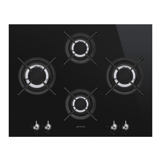
This is a class 3 built-in hob. We advise you to read this manual carefully, which contains all the instructions for maintaining the appliance’s aesthetic and functional qualities. For further information on the product: www.smeg.com...
Instructions 1 Instructions • Make sure that the flame-spreader crowns are correctly positioned in 1.1 General safety instructions their housings with their respective burner caps. Risk of personal injury • Be aware of how rapidly the • During use the appliance and its cooking zones heat up.
Page 3
Instructions • Switch the appliance off Risk of damaging the appliance immediately after use. • Use wooden or plastic utensils. • DO NOT MODIFY THIS • Do not seat on the appliance. APPLIANCE. • Do not use steam jets to clean the •...
Page 4
Instructions • Do not use steam jets to clean the • Installation with flexible hose must appliance. be carried out so that the length of the piping does not exceed 2 metres • Do not use rough or abrasive when fully extended as regards materials or sharp metal scrapers.
Instructions For this appliance 1.4 Appliance purpose • This appliance is intended for • Do not obstruct ventilation cooking food in the home openings and heat dispersal slots. environment. Every other use is • Do not insert pointed metal considered improper. objects (cutlery or utensils) into •...
Instructions • Consign the appliance to the 1.7 How to read the user manual appropriate selective collection This user manual uses the following reading centres for electrical and conventions: electronic equipment waste, or Instructions deliver it back to the retailer when General information on this user purchasing an equivalent product, manual, on safety and final...
Description 90 cm AUX = Auxiliary R = Rapid SR = Semi-rapid UR = Ultra rapid RR = Reduced rapid UR* = Ultra rapid 2.2 Symbols Cooking zones Burner knobs Front left Centre left Rear left Central Rear right Central right Useful for lighting and adjusting the hob burners.
Description 2.3 Available accessories WOK ring Useful when using a wok. The accessories intended to come into contact with food are made of materials that comply with the provisions of current legislation. Original supplied and optional accessories can be requested to Authorised Assistance Centres.
3 Use Improper use 3.1 Instructions Risk of damage to surfaces Improper use Danger of burns • Do not use aluminium foil to cover the burners or hob body. • Make sure that the flame-spreader • Cooking vessels or griddle plates crowns are correctly positioned in their should be placed inside the perimeter of seats with their respective burner caps.
3.3 Using the hob Correct positioning of the flame- spreader crowns and burner caps All the appliance’s control and monitoring devices are located together on the front Before lighting the hob burners, make sure panel. The burner controlled by each knob that the flame-spreader crowns are is shown next to the knob.
Page 12
Correct positioning of the grids Ring reducers Under the grids there are silicone rests with The ring reducers must be rested on the hob a hole that must be centred onto the grid. Make sure they are properly matching fixing pins on the surface. positioned.
Page 13
Practical tips for using the hob Using a griddle For better burner efficiency and to minimise A few precautions are necessary if you wish gas consumption, use pans with lids and of to use a griddle: suitable size for the burner, so that the •...
Cleaning and maintenance 4 Cleaning and maintenance 4.2 Cleaning the appliance To keep the surfaces in good condition, 4.1 Instructions they should be cleaned regularly after use. Let them cool first. Improper use Ordinary daily cleaning Risk of damage to surfaces Always use only specific products that do not contain abrasives or chlorine-based •...
Page 15
Cleaning and maintenance Cooking hob grids Igniters and thermocouples Remove the grids and clean them with For correct operation the igniters and lukewarm water and non-abrasive thermocouples must always be perfectly detergent. Make sure to remove any clean. Check them frequently and clean encrustations.
Installation 5 Installation 5.1 Clearances above and around domestic appliances This appliance must be installed by an highest part of the hob shall be protected authorised person in accordance with this for the full width and depth of the instruction manual, AS/NZS 5601.1 – cooking surface area in accordance Gas installations (installation and pipe with Clause 5.12.1.2.
Installation 3. Additional requirements for 5.2 Safety instructions Freestanding and Elevated Cooking Heat production during appliance Appliaces – (Measurements D & E) operation Where D, the distance from the Risk of fire periphery of the nearest burner to a horizontal combustible surface is less •...
Installation 5.3 Section cut from the countertop 5.4 Mounting Over built-in oven unit The following operation requires building and/or carpentry work The clearance between the hob and the and must therefore be carried out kitchen furniture or other installed by a competent tradesman. appliances must be enough to ensure Installation can be carried out on sufficient ventilation and air discharge.
Page 19
Installation Over empty kitchen unit or drawers Fixing brackets If there are other pieces of furniture (lateral Screw the fixing brackets (A) into the holes walls, drawers, etc.), dishwashers or fridges on the sides of the bottom casing to under the hob, a double-layer wooden properly fasten the hob to the structure.
Installation 5.5 Gas connection With steel hob To prevent leakage of liquid between the Gas leak frame of the hob and the work surface, put Danger of explosion the insulating seal provided in position before assembly. • After carrying out any operation, check 1.
Page 21
Installation Connection of the appliance to the gas To check the operating pressure of the supply must be in accordance with the appliance it is recommended at least 2 requirements of AS5601. A ½” BSP large size burners are used. Ensure connector at the inlet is recommended and appliance is secured to wall when the gas supply line to the appliance must be...
Page 22
Installation Room ventilation When the job is complete, the installer must issue a certificate of conformity. The room containing the appliance should have a permanent air supply in accordance with the standards in force. The room where the appliance is installed must have enough air flow needed for the regular combustion of gas and the necessary air change in the room itself.
Installation 5.6 Adaptation to different types of gas 3. Pull the knobs and the knob bezels upwards to remove them. If other types of gas are to be used, the nozzles must be replaced and the primary air must be adjusted. In order to replace the nozzles and adjust the burners, the hob top must be removed.
Page 24
Installation 5. Remove the fastening plates and the hob 3. Adjust the air flow by moving the air top. regulator B to obtain the distance D given in the corresponding table. 4. After adjusting each burner, reassemble the appliance correctly. Adjusting the minimum setting for natural or town gas 1.
Page 25
Installation Adjusting the minimum setting for LPG Lubricating the gas cocks Tighten the screw located at the side of the Over time the gas taps may become difficult to turn and get blocked. Clean them tap rod clockwise all the way. internally and replace the lubrication Following adjustment to a gas grease.
Installation 5.7 Electrical connection The appliance can work in the following modes: Power voltage • 220-240 V 1N~ Danger of electrocution 220-240V~ 1 mm • Have the electrical connection performed by authorised technical personnel. 20 mm • Use personal protective equipment. 3 x 1 mm²...
Installation 5.8 For the installer • The plug must be accessible after installation. Do not bend or trap the power cable. • The appliance must be installed according to the installation diagrams. • Do not try to unscrew or force the threaded elbow of the fitting.