Table of Contents
Advertisement
Quick Links
Advertisement
Table of Contents

Related Manuals for horiba F-70 Series


Summary of Contents for horiba F-70 Series
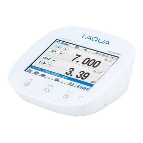
- Page 1 Instruction Manual 表紙は別途デザインの表紙とする pH/ION METER F-73...
- Page 2 HORIBA, Ltd., any malfunctioned or damaged Product attributable to responsibility of HORIBA, Ltd. for a period of one (1) year from the delivery unless otherwise agreed with a written agreement. In any one of the following cases, none of the warranties set forth herein shall be extended;...
- Page 3 REGULATIONS ■ Conformable Directive This equipment conforms to the following directives and standards: Directives: The EMC Directive 2004/108/EC The Low Voltage Directive 2006/95/EC Standards: [the EMC Directive] EN61326-1:2006 Class B, Basic requirements [the Low Voltage Directive] EN61010-1:2010(Ed.3.0) ● Installation Environment This product is designed for the following environment.
- Page 4 REGULATIONS ■ FCC Rules Any changes or modifications not expressly approved by the party responsible for compliance shall void the user's authority to operate the equipment. ● WARNING This equipment has been tested and found to comply with the limits for a Class A digital device, pursuant to part 15 of the FCC Rules.
- Page 5 SAFETY OPERATION ■ Hazard Classification and Warning Symbols Warning messages are described in the following manner. Read the messages and follow the instructions carefully. ● Hazard classification This indicates an imminently hazardous situation which, if not avoided, will result in death or serious injury. This signal word is to be limited to the most extreme situations.
- Page 6 SAFETY OPERATION ■ Safety Precautions This section provides precautions to enable you to use the product safely and correctly and to prevent injury and damage. The terms of DANGER, WARNING, and CAUTION indicate the degree of imminency and hazardous situation. Read the precautions carefully as it contains important safety messages.
- Page 7 SAFETY OPERATION ■ Product Handling Information ● Operational Precautions Do not drop, crash, or give any physical impact on the instrument. ● Do not immerse the instrument into alcohol, organic solvent, strong ● acid, strong alkaline, or the like. The instrument body contains ABS resin, acrylic resin, and some rubber parts.
- Page 8 MANUAL INFORMATION ■ Description in This Manual This interprets the necessary points for correct operation and notifies the important points for handling the instrument. This indicates the part of where to refer the information. HINT! This indicates reference information. MANUAL INFORMATION...
-
Page 9: Table Of Contents
Contents Chapter 1 OVERVIEW ................1 1.1 Description of Each Part ................ 1 1.1.1 Rear ....................1 1.1.2 Display .................... 1 1.1.3 Left Side ..................2 1.1.4 Right Side ..................2 1.1.5 Accessories ..................2 1.1.6 Operation Keys ................3 1.1.7 Icons (Icon Bar) ................ - Page 10 Contents 3.1.3 Calibration Interval ................ 36 3.1.4 Checking Before Use ..............37 3.2 pH Calibration ..................38 3.2.1 Calibration Preparation ..............38 3.3 Checking Before Use ................41 3.4 Calibration for Custom selection ............42 3.4.1 Calibration Preparation ..............42 3.5 pH Measurement Setting ..............
- Page 11 Contents 5.1 mV Measurement Setting ..............62 5.2 Temperature Setting ................62 5.2.1 Solution Temperature Entry in MTC (Manual Temperature Setting) ......... 63 5.3 Alarm Setting ..................63 5.3.1 Input Upper or Lower Limit Values ..........64 5.4 Electrode Model Setting ............... 65 5.4.1 Electrode Model Selection ............
- Page 12 Contents Chapter 9 Data ..................90 9.1 Measurement data_All ................90 9.2 Deleting Saved Data ................90 9.3 Measurement data_latest50 ..............91 9.4 Measured data_Search ................. 91 9.5 Cal. results_All ..................92 9.6 Copy all Meas. Data ................92 9.7 Delete all meas. Data ................93 9.8 Delete all cal.
-
Page 13: Chapter 1 Overview
Chapter 1 OVERVIEW Chapter 1 OVERVIEW This chapter describes functions and basic operations of the instrument. 1.1 Description of Each Part 1.1.1 Rear CH2 reference electrode CH1 reference electrode CH2 measurement electrode CH1 measurement electrode CH2 for temperature electrode CH1 for temperature electrode 1.1.2 Display Status bar Touch panel... -
Page 14: Left Side
Instructs the usage of the instrument. Quick manual Instructs the operations of calibration and measurement. Ferrite core Attach this device to the AC adapter cable to reduce interference. *Clock battery (CR-2032) is put into the battery cover at the instrument bottom. HORIBA... -
Page 15: Operation Keys
Chapter 1 OVERVIEW 1.1.6 Operation Keys Operation key Function Turns ON or OFF the power. POWER (Press and hold for 2 seconds or more.) Displays the calibration screen (CAL screen). MEAS Displays the measurement screen (MEAS screen). DATA Displays the data screen (DATA screen). The POWER key does not work for 10 seconds after the AC adapter is connected. -
Page 16: Icons (Icon Bar)
Used to delete calibration data or the data saved in Trash box the instrument. Used to start and stop the operations of measurement and calibration, and to change to the Operation instantaneous value display. The icon label depends on the corresponding operation. HORIBA... -
Page 17: Status Icons
Chapter 1 OVERVIEW 1.1.8 Status Icons The icons displayed on the top of the touch panel show information on the instrument. Status icon Function Shows that the automatic hold function is ON, and that the end point is determined automatically according to input Auto hold signals from the electrode based on the pre-selected stability criterion of measurement values. -
Page 18: Meas Screen
The displayed temperature is the electrode electrode temperature (ATC). connection Not displayed: The displayed temperature is preset indicator value (MTC). Not displayed: An instantaneous value is displayed. HOLD indicator Blinking: In-process for HOLD Lighting up: HOLD completed. HORIBA... -
Page 19: Basic Operation Of Touch-Panel And Touch-Key
Chapter 1 OVERVIEW 1.2 Basic Operation of Touch-Panel and Touch-Key The instrument has touch panel and keys and you can operate it by touching the screen. The 3 basic operations of Tap, Flick, and Drag allow you to operate the instrument intuitively. -
Page 20: Function And Operation Of The Meas Screen
You can shift the screen to the digital, graph or analog screen by flicking it. Digital display If arrows, like , appear when you touch the screen, you can flick in the directions to switch the screen display. Graph display Analog display HORIBA... - Page 21 Chapter 1 OVERVIEW ● Graph display You can change the scale of the vertical axis in the graph display. It allows you to check a small change in measurement values. The vertical axis is zoomed in. The displayed range narrows. Displays the next or Displays the the latest data.
-
Page 22: Function And Operation Of The Cal Screen
, appear when you touch the screen, you can flick in the directions to switch the screen display. You can change the width of graph so that you can easily recognize variation of the indicated value at the graph screen. HORIBA... -
Page 23: Assembling The Electrode Stand
Chapter 1 OVERVIEW The width of measurement range becomes narrower to enlarge the display of measurement values. Displays the Displays the next or previous data. the latest data. The width of measurement range becomes wider to reduce the display of measurement values. By tapping the graph screen after you have changed it, the graph screen range optimizes automatically and displays the latest data. -
Page 24: Connecting The Electrode
Do not screw in it. 1.6.2 Temperature Connector Insert the temperature connector into the jack socket on the instrument. If the temperature connector is unconnected or the connection is wrong, the MTC set temperature is displayed as the liquid temperature. HORIBA... -
Page 25: Connecting The Power Source
Chapter 1 OVERVIEW 1.7 Connecting the Power Source Insert the AC adapter cable by fitting with the connector socket of in the instrument. ・ Do not insert the cable with force when the connectors do not match. ・ Attach the provided ferrite core to the AC adapter cable. -
Page 26: Connecting The Personal Computer
If you change the transfer formats, power OFF both of the instrument and the personal computer once, and then turn ON them again. ・ For the details of communication commands, register with our website and see the free download page of manuals. HORIBA... -
Page 27: Turn On The Power
Chapter 1 OVERVIEW 1.10 Turn on the Power Press and hold the POWER key for 2 seconds or longer. Following the startup screen, the MEAS screen will be displayed. ・ The POWER key does not work for 10 seconds after the AC adapter is connected. Wait for a while after connecting AC adapter. -
Page 28: Chapter 2 Before Measurement (Meter Set)
HOLD TYPE item. Select the measurement stability condition of the 6 types (EXACT, NORMAL, BRIEF, TIME, CUSTOMIZE, Manual) in the AUTO HOLD selection screen. To cancel the operation, tap to return to the previous screen. HORIBA... -
Page 29: Custom Setting
Chapter 2 Before Measurement (Meter SET) Each HOLD condition is described below. Stability condition Function In the AUTO HOLD mode, the instrument judges potential stability Auto hold automatically to set the measurement values. Content Measuring Mode Temperature target Time (s) Criteria 【Default】... -
Page 30: Sample Name Setting
Up to 10 characters can be input. The setting applies. To cancel the settings, tap to return to the previous screen. HINT! To delete a registered sample name, tap on the right of the sample name, enter noth- ing, and tap HORIBA... -
Page 31: Interval Memory Setting
Chapter 2 Before Measurement (Meter SET) 2.5 Interval Memory Setting The measured data can be stored at set time intervals. on the right of the Interval memory item and select ON. Enter Interval Time Display the Time item when select ON. on the right of the Time item. -
Page 32: Usb Memory Setting
To cancel the operation, tap When the ejection is completed, a notice message will appears. Tap If you remove a USB memory from the instrument in a way other than mentioned above, data may not be saved correctly or data may be corrupted. HORIBA... - Page 33 Chapter 2 Before Measurement (Meter SET) Format Use this item to format a USB memory in FAT16. Note that formatting deletes all stored data. on the right of the Format item and tap in the execution confirmation screen. To cancel the operation, tap A message that formatting is in progress appears during formatting.
-
Page 34: Printer Setting
Auto printout item and select ON. Printout Layout This item allows you to change printing contents. on the right of the Printout Layout item. The printing format screen is displayed. to return to the previous screen. HORIBA... - Page 35 Chapter 2 Before Measurement (Meter SET) ● When selecting CUSTOMIZE CUSTOMIZE allows you to select items you want to print out among Measurement date/time, User name, Settings, Sensor info•Cal. User. Select CUSTOMIZE from Printout Layout, and on the right of the each printing item. is ON: The item is selected.
-
Page 36: Screen Settings
You can adjust the display brightness by tapping , or by dragging on the scale. on the right of the Display brightness item. When the screen becomes the desired brightness, tap To cancel the operation, tap to return to the previous screen. HORIBA... - Page 37 Chapter 2 Before Measurement (Meter SET) Power Saving Mode You can set the time for power saving mode. on the right of the Power saving mode item and select ON. ● Back light off time When selecting ON for Power saving mode, the Back light off time item is displayed.
-
Page 38: Sound Setting
When the sound volume is set to 0, the instrument is in the mute mode. on the right of the Sound volume set- tings item. When the screen becomes the desired volume, To cancel the operation, tap to return to the previous screen. HORIBA... -
Page 39: Language Setting
Chapter 2 Before Measurement (Meter SET) 2.10 Language Setting You can change language settings. on the right of the Language item. Select the language. To cancel the operation, tap 2.11 Security Setting Security setting allows you to set a password for an administrator of the instrument. - Page 40 When the Security setting is ON, at least 1 administrator is required for the instrument. Administrators have to keep the password. We recommend registering 2 or more administrators. Administrator's names are marked with a star on the user selection screen. HORIBA...
-
Page 41: User Entry/Info Change/Delete
Chapter 2 Before Measurement (Meter SET) 2.12 User Entry/Info Change/Delete When an operater is registered, the operater name can be put in measurement/calibration information, data printouts, data memory. on the right of the User entry/info change/delete item, when user registration, change password and user deletion. - Page 42 When the Security setting is ON, at least 1 administrator is required for the instrument. Administrators have to keep the password. We recommend registering 2 or more administrators. Administrator's names are marked with a star on the user selection screen. HORIBA...
-
Page 43: Date Setting
Chapter 2 Before Measurement (Meter SET) 2.13 Date Setting You can set the date and time. on the right of the Date/Time setting item. The Date/Time setting screen is displayed. to return to the previous screen. Date You can set the date. on the right of the Year, month, day item. -
Page 44: Analog Output Adjustment
The Output value adjustment screen is dis- played. to adjust the analog output volt- age. To cancel the operation, tap to return to the previous screen. HORIBA... -
Page 45: Temperature Sensor Calibration
Chapter 2 Before Measurement (Meter SET) 2.15 Temperature Sensor Calibration You can perform calibration of the temperature sensor. on the right of the Temp. calibration item. The Temp. calibration setting screen is dis- played. To cancel the operation, tap to return to the previous screen. -
Page 46: Resetting To Factory Defaults
Press and hold the POWER key for 2 seconds to turn ON. If you disconnect the AC adapter after powering OFF, the POWER key does not work for 10 seconds after the AC adapter is reconnected. Wait for a while after reconnecting AC adapter. HORIBA... -
Page 47: Chapter 3 Ph Measurement
Chapter 3 pH Measurement Chapter 3 pH Measurement 3.1 pH Calibration Setting This section describes the procedures to set the conditions of pH calibration. Tap the channel setting and the measurement item in the MEAS screen to set "CH1" and "pH". Press the CAL key to display the pH CAL screen. -
Page 48: Calibration Interval
Display the Cal. Interval item when select ON at the calibration interval. Tap on the right of the Cal. Interval item. Enter the interval day in the numerical-key screen. The setting applies. To cancel the settings, tap HINT! We recommend performing calibration once a day, before measurement. HORIBA... -
Page 49: Checking Before Use
Chapter 3 pH Measurement 3.1.4 Checking Before Use If you set the Checking Before Use setting to ON, it allows you to check repeatability after calibration by comparing the measured value of pH7 standard solution with the calibration result. After the set point calibrations are completed, repeatability is automatically checked using the deviation between the calibrated and measured values at pH7. -
Page 50: Ph Calibration
Wash the pH electrode with pure water (ion exchange water), and wipe it off by filter paper or tissue paper. Open the internal solution filler port of the pH electrode. Immerse the pH electrode into a beaker of pH7 standard solution. HORIBA... - Page 51 Chapter 3 pH Measurement Calibration of the 1st point to start calibration with the 1st point. The measurement value is displayed, and the HOLD indicator blinks until the reading stabilizes. To stop calibration tap while the HOLD indicator blinks. The brinking interval of the HOLD indicator may not be constant depending on the reading stability level.
- Page 52 This appears only for calibration data on the DATA screen. (Calibration with 85% or less sensitivity Electrode NG 85% or less than does not apply to measurement, but is recorded on the DATA screen.) Replace the electrode. HORIBA...
-
Page 53: Checking Before Use
Chapter 3 pH Measurement 3.3 Checking Before Use When the preliminary check function is ON, you can check repeatability with pH7 standard solution. Use this function to check measurement accuracy by checking repeatability. An operation guide is displayed after the 2nd point calibration is completed. Check the repeatability according to the operation guide. -
Page 54: Calibration For Custom Selection
HOLD indicator is lit up and the progress bar shows that the 1st point calibraion is completed. After the 1st point calibration is completed, tap to proceed to the 2nd point calibration. Perform the 2 point and later point calibraton in the same procedures as above. HORIBA... -
Page 55: Ph Measurement Setting
Chapter 3 pH Measurement 3.5 pH Measurement Setting This section describes the procedures to set the conditions of pH measurement. Tap the channel setting and the measurement item in the MEAS screen to set "CH1" and "pH". and tap "CH1 MEAS SET". pH measurement setting items are displayed. -
Page 56: Temperature Compensation Setting
MTC (Manual Temperature Compensation) When selecting MTC for the TEMP setting item, the Temperature item is displayed. on the right of the Temperature item. Enter the sample temperature on the numerical- key screen. The setting applies. To cancel the settings, tap HORIBA... -
Page 57: Temperature Conversion Function Setting
Chapter 3 pH Measurement 3.8 Temperature Conversion Function Setting To use the temperature conversion function, set TEMP conversion to ON. The measured pH value of a sample varies with the temperature. In addition, the change degree with temperature depends on the sample property. -
Page 58: Alarm Setting
When selecting ON the Alarm, lower limit item, the Lower limit value, tap on the right of the Lower limit value item. Enter a lower limit value on the numerical-key screen. The setting applies. To cancel the settings, tap HORIBA... -
Page 59: Electrode Model Setting
Chapter 3 pH Measurement 3.10 Electrode Model Setting When an electrode model is set, the model name can be displayed on data printouts or recorded in saved data. Select the electrode model to be used for measurement. You can set a desired name with up to 10 characters by selecting the Customize item. 3.10.1 Electrode Model Selection on the right of the Electrode model item. -
Page 60: Electrode Lot No. Setting
Enter the electrode lot No. in the numerical screen. Up to 8 digits can be entered. To cancel the settings, tap HINT! To delete a registered electrode lot No., tap on the right of the electrode lot No., enter nothing, and tap HORIBA... -
Page 61: Ph Measurement
Chapter 3 pH Measurement 3.12 pH Measurement This section describes the procedures of pH measurement. Tapping allows you to check the information of the current calibration (operator, cali- bration date, calibration points). Wash the electrode with pure water (ion exchange water), and wipe it off either with filter paper or tissue paper. -
Page 62: Chapter 4 Ion Measurement
Up to 5 points calibration is possible. Set the number of the calibration points. on the right of the Calibration Points item. in the Calibration points setting screen to set the calibration points. The setting applies. To cancel the settings, tap HORIBA... -
Page 63: Checking Before Use
Chapter 4 ION Measurement 4.1.2 Checking Before Use If you set the Checking Before Use setting to ON, it allows you to check repeatability after calibration by comparing the measured value of pH7 standard solution with the calibration result. After the set point calibrations are completed, repeatability is automatically checked using the deviation between the calibrated and measured values at pH7. -
Page 64: Ion Calibration
Open the internal solution filler port of the ION electrode. Immerse the ION electrode into a beaker of the standard solution used for the 1st point calibration. HORIBA... - Page 65 Chapter 4 ION Measurement Calibration of the 1st point Tap the ION value at the right of "Set:" to display the numerical-key screen. when the mol/L unit is set) to select the auxiliary unit of standard solution used for calibration. Each tapping switches the unit as g/L -->...
-
Page 66: Checking Before Use
An operation guide is displayed after the 2nd point calibration is completed. Check the repeatability according to the operation guide. After the set point calibrations are completed, repeatability is automatically checked using the deviation between the calibrated and measured values at the 1st point. HORIBA... -
Page 67: Ion Measurement Setting
Chapter 4 ION Measurement 4.4 ION Measurement Setting This section describes the procedures to set the conditions of ION measurement. Tap the channel setting and the measurement item in the MEAS screen to set "CH1" and "ION". and tap "CH1 MEAS SET". ION measurement setting items are displayed. -
Page 68: Temperature Compensation Setting
MTC (Manual Temperature Compensation) When selecting MTC for the TEMP setting item, the Temperature item is displayed. on the right of the Temperature item. Enter the sample temperature on the numerical- key screen. The setting applies. To cancel the settings, tap HORIBA... -
Page 69: Alarm Setting
Chapter 4 ION Measurement 4.7 Alarm Setting When the measurement values exceeds the set upper or lower limit, the instrument detects it to display the notice on the screen or to output the signal from the external ouput terminal. If the measurement values exceeds the alarm range, the color of the pertinent channel "CH"... - Page 70 To change the unit (mg/L, µg/L, etc.), tap on the unit change key on the right of the numerical-key screen. The setting applies. To cancel the settings, tap Even when unit or ion type is changed, the alarm set value will not change. HORIBA...
-
Page 71: Electrode Model Setting
Chapter 4 ION Measurement 4.8 Electrode Model Setting When an electrode model is set, the model name can be displayed on data printouts or recorded in saved data. Select the electrode model to be used for measurement. You can set a desired name with up to 10 characters by selecting the Customize item. 4.8.1 Electrode Model Selection on the right of the Electrode model item. -
Page 72: Ion Valency Setting (For Customized Electrode Model Only)
Enter the electrode lot No. in the numerical-key screen. Up to 8 digits can be entered. To cancel the settings, tap HINT! To delete a registered electrode lot No., tap on the right of the electrode lot No., enter nothing, and tap HORIBA... -
Page 73: Ion Measurement
Chapter 4 ION Measurement 4.10 ION Measurement This section describes the procedures of ION measurement. Wash the electrode with pure water (ion exchange water), and wipe it off either with filter paper or tissue paper. Open the internal solution filler port of the electrode. -
Page 74: Chapter 5 Mv Measurement
In MTC, measure the solution temperature and enter the value in advance. The instrument displays the entered temperature. If the temperature terminals of the instruction and electrode are not connected, temperature setting is performed in MTC even when ATC is set. HORIBA... -
Page 75: Solution Temperature Entry In Mtc (Manual Temperature Setting)
Chapter 5 mV Measurement 5.2.1 Solution Temperature Entry in MTC (Manual Temperature Setting) Display the Temperature item when select MTC. on the right of the Temperature item. Enter the solution temperature on the numerical- key screen. The setting applies. To cancel the settings, tap 5.3 Alarm Setting When the measurement values exceeds the set upper or lower limit, the instrument detects it to display the notice on the screen or to output the signal from the external ouput... -
Page 76: Input Upper Or Lower Limit Values
When selecting ON the Alarm, lower limit item, the Lower limit value, tap on the right of the Lower limit value item. Enter an upper limit value on the numerical-key screen. The setting applies. To cancel the settings, tap HORIBA... -
Page 77: Electrode Model Setting
Chapter 5 mV Measurement 5.4 Electrode Model Setting When an electrode model is set, the model name can be displayed on data printouts or recorded in saved data. Select the electrode model to be used for measurement. You can set a desired name with up to 10 characters by selecting the Customize item. 5.4.1 Electrode Model Selection on the right of the Electrode model item. -
Page 78: Electrode Lot No. Setting
Enter the electrode lot No. in the numerical-key screen. Up to 8 digits can be entered. To cancel the settings, tap HINT! To delete a registered electrode lot No., tap on the right of the electrode lot No., enter nothing, and tap HORIBA... -
Page 79: Mv Measurement
Chapter 5 mV Measurement 5.6 mV Measurement This section describes the procedures of mV measurement. Wash the electrode with pure water (ion exchange water), and wipe it off either with filter paper or tissue paper. Open the internal solution filler port of the electrode. -
Page 80: Chapter 6 Orp Measurement
When the calibration is completed, the HOLD indicator is lit, displaying the calibration result. after checking the calibration result to return to the CAL screen. To start ORP measurement, press the MEAS key. HORIBA... -
Page 81: Orp Measurement Setting
Chapter 6 ORP Measurement 6.2 ORP Measurement Setting This section describes the procedures to set the conditions of ORP measurement. Tap the channel setting and the measurement item in the MEAS screen to set "CH1" and "ORP". and tap "CH1 MEAS SET". ORP measurement setting items are displayed. -
Page 82: Alarm Setting
When selecting ON the Alarm, lower limit item, the Lower limit value, tap on the right of the Lower limit value item. Enter an upper limit value on the numerical-key screen. The setting applies. To cancel the settings, tap HORIBA... -
Page 83: Electrode Model Setting
Chapter 6 ORP Measurement 6.5 Electrode Model Setting When an electrode model is set, the model name can be displayed on data printouts or recorded in saved data. Select the electrode model to be used for measurement. You can set a desired name with up to 10 characters by selecting the Customize item. 6.5.1 Electrode Model Selection on the right of the Electrode model item. -
Page 84: Electrode Lot No. Setting
Enter the electrode lot No. on the numerical-key screen. Up to 8 digits can be entered. To cancel the settings, tap HINT! To delete a registered electrode model name, tap on the right of the electrode model name, enter nothing, and tap HORIBA... -
Page 85: Orp Measurement
Chapter 6 ORP Measurement 6.7 ORP Measurement This section describes the procedures of ORP measurement. Wash the electrode with pure water (ion exchange water), and wipe it off either with filter paper or tissue paper. Open the internal solution filler port of the electrode. -
Page 86: Chapter 7 Application Mode
For the sample addition method, a small amount of sample is added to the standard solution for the target ion species, to increase the concentration of the target ion. The original ion concentration is obtained from the change in electric potential when the sample is added. HORIBA... -
Page 87: General Cautions For Standard Addition Method
Chapter 7 Application Mode Sample addition method (Single) The sample is added only once to the standard solution of the target ion species. Sample addition method (Double) The sample is added twice to the standard solution of the target ion species. This mode is used to obtain the electric potential slope of the electrode used. -
Page 88: Known Addition Method (Single) Measurement
Immerse the ion electrode in sample solution and tap The measurement starts. When the indication stabilizes, the HOLD indicator lights up and the measurement value is determined. to proceed to the next measurement. HORIBA... -
Page 89: Known Addition Method (Double) Measurement
Chapter 7 Application Mode Immerse the ion electrode in sample solution after the additive standard solution and tap The measurement starts. When the measurement is completed, concentration of the sample and the measuring condition are displayed as measurement results. to return to the ION standard addition mode screen. 7.1.6 Known Addition Method (Double) Measurement This mode is used to obtain the concentration of the ion species under measurement by adding a small amount of the target ions to the sample solution twice, thus increasing the... -
Page 90: Sample Addition Method (Single) Measurement
Measurement condition setting on the right of the Sample addition method item in the ION standard addition mode screen. on the right of the Sample add. method (Single) item. HORIBA... - Page 91 Chapter 7 Application Mode Set the measurement condition in the Sample add. method (Single) screen. Enter sample volume, concentration of the additive standard solution, volume of the additive standard solution and electrode slope. key after complete setting. The MEAS screen is displayed. To return the set value to default, tap the Setting item and range Volume of the additive sample solution:...
-
Page 92: Sample Addition Method (Double) Measurement
Immerse the ion electrode in sample solution and tap The measurement starts. When the indication stabilizes, the HOLD indicator lights up and the measurement value is determined. to proceed to the next measurement. Immerse the ion electrode in the 1 sample solution and tap The measurement starts. HORIBA... - Page 93 Chapter 7 Application Mode to proceed to the next measurement. Immerse the ion electrode in the 2 sample solution and tap The measurement starts. When the measurement is completed, concentration of the sample and the measuring condition are displayed as measurement results. to return to the ION standard addition mode screen.
-
Page 94: Chapter 8 Periodic Inspection Mode
The setting applies. The check mark on the current setting item is displayed. To cancel the settings, tap The setting of pH periodic inspection mode is completed. Hereinafter, how to set each pH periodical inspection item is described. HORIBA... -
Page 95: Jis Mode
Chapter 8 Periodic Inspection Mode 8.1.2 JIS Mode According to JIS regulation, the measurement with a solution of pH9 is given three times after measurement by standard solutions of pH7 and pH4. The result is displayed on the screen. When the periodic inspection mode starts, the operation guide is shown on the screen. - Page 96 When the above measurement does not solve the defective conditions, perform the followings. ・ Clean the electrode. ・ Confirm the right standard solution is used. ・ Check if the electrode is deteriorated, and replace it to new one if necessary. HORIBA...
-
Page 97: Pharmacopoeia Mode
Chapter 8 Periodic Inspection Mode 8.1.3 Pharmacopoeia Mode After measurement with the standard solutions of pH7 and pH4 (or pH9), the measurement using the standard solution of pH7 is repeated 5 times, and the result is displayed. This check procedures conform to the regulation of the Japanese Pharmacopoeia (JP). -
Page 98: Simulator (X-51) Mode
Set the resolution to 0.001 pH in the pH SETUP screen. Set the temperature compensation to ATC. According to the operation guide, perform functional check as calibration by the standard solutions of pH7, pH4 in the following order. (1) Calibration by standard solutions pH6.865 pH4.008 HORIBA... - Page 99 Chapter 8 Periodic Inspection Mode (2) Linearity check pH0.000 pH4.000 pH7.000 pH10.000 pH14.000 (3) Indication check by inputting high impedance Input pH0.000 Input pH14.000 (4) Temperature indication check The displayed pH values at this time have nothing to do with the check result. 0.0°C 30.0°C 60.0°C...
-
Page 100: Ion Periodic Inspection Mode Setting
10.0 mmol/L Simulated linearity check 100 µmol/L 240 mV 120 mV 10.0 mmol/L 0 mV 1.00 mol/L −120 mV 100 mol/L Simulated temperature check 0.0°C 30.0°C 60.0°C 100.0°C When all the check is completed, the result is outputted automatically. HORIBA... -
Page 101: Comment Input
Chapter 8 Periodic Inspection Mode 8.3 Comment Input A comment can be entered up to 100 characters. Use this fuction to record periodical checks, etc. to use the function. To delete the content input previously, tap F-73... -
Page 102: Chapter 9 Data
"DELETE" is displayed under the ID number. to return the Measured data_All screen. "del" is indicated as the ID of the data to be deleted. After that, tap to execute deletion. To execute, tap . Not to execute, tap HORIBA... -
Page 103: Measurement Data_Latest50
Chapter 9 Data 9.3 Measurement data_latest50 You can check just the latest 50 data. The data are sorted in descending order of measurement data. 9.4 Measured data_Search You can search saved data by one of measurement item, operator, or sample name. (You can not use mutiple seach conditions at a time.) on the right of the Measured... -
Page 104: Cal. Results_All
Copy all meas. Data completion screen. Before copying data, make sure that sufficient capacity is available in the USB memory. If the copy stops in the middle, turn OFF the power and reboot the instrument, and then execute the copy again. HORIBA... -
Page 105: Delete All Meas. Data
Chapter 9 Data 9.7 Delete all meas. Data You can delete all measurement data saved in the instrument. on the right of the Delete all meas. Data to delete the all measurement data. To cancel the operation, tap in the Delete all meas. DATA screen. 9.8 Delete all cal. -
Page 106: Chapter 10 Specifications
±0.1°C ±1 digit Measuring range ±1999.9 mV mV (ORP) Resolution 0.1 mV Repeatability ±0.1 mV ±1 digit Measuring principle Ion electrode 0.00 µg/L to 999 g/L (mol/L) Measuring range Resolution Valid numbers 3 digits Repeatability ±0.5% ±1 digit of full scale HORIBA... -
Page 107: Default Settings
Chapter 10 Specifications 10.2 Default Settings 10.2.1 Meter Default Settings Default Item Selection item/Setting range values Security management Security Enable/Disable Disable function EXACT/NORMAL/BRIEF/ Hold condition Hold setting mode NORMAL TIME/CUSTOM/OFF (Manual) In selecting Time setting value 2 seconds to 999 seconds 10 seconds "TIME"... -
Page 108: Measurement Condition Default Settings (Can Be Set Per Operator)
Standard solution NIST/USA/Custom/China NIST Calibration points 1 to 5 points 2 points Calibration interval setting Enable/Disable Disable pH calibration Calibration interval 1 to 999 days 3 days condition Preliminary check Enable/Disable Disable JIS/Pharmacopeia/ Periodical check X-51 X-51 (Digital simulator) HORIBA... - Page 109 Chapter 10 Specifications Selection item/ Default Item Setting range values Upper limit Enable/Disable Disable value setting Lower limit Enable/Disable Disable value setting Alarm condition Upper limit ±1999.9 mV 1999.9 mV value Lower limit −1999.9 mV ±1999.9 mV value measurement ATC (Automatic temperature condition Temperature compensation)/...
- Page 110 MTC (Manual temperature Temperature compensation) setting Temperature input value in 0.0°C to 100.0°C 25.0°C selecting "MTC" Model None Electrode data lot No. None Calibration points 1 to 5 points 2 points calibration Preliminary check Enable/Disable Disable condition Sample ID None HORIBA...
- Page 111 Chapter 10 Specifications Selection item/ Default Item Setting range values Japanese/English/ Language English Chinese/Korean STANDARD, COOL, Screen theme STANDARD MONOTONE, KYOTO Brightness 1 to 10 Screen Power saving setting Enable/Disable Disable mode Back light off 1 to 999 minutes 60 minutes time Interface condition...
-
Page 112: Options
Chapter 10 Specifications 10.3 Options This section lists spare and optional parts for the pH meter.These parts are possible through HORIBA distributors. Place an order specifying their name, model, and part number. Part name Part number Remarks AC adapter, 3014031951... - Page 113 For any question regarding this product, please contact your local agency, or inquire from the Customer Registration website (http://www.horiba.com/register) 1st edition: October 2011 CODE: GZ0000260895...
- Page 114 表紙は別途デザインの表紙とする...
Need help?
Do you have a question about the F-70 Series and is the answer not in the manual?
Questions and answers