Table of Contents
Advertisement
Quick Links
Commercial Hybrid Water Heating System
Demand Duo™ Model
CHS199100CU
WARNING
WARNING
•
Do not store or use gasoline or other flammable vapors and liquids in the vicinity of this or any other
appliance.
•
WHAT TO DO IF YOU SMELL GAS
−
Do not try to light any appliance.
−
Do not touch any electrical switch; do not use any phone in your building.
−
Immediately call your gas supplier from a neighbor's phone. Follow the gas supplier's instructions.
−
If you cannot reach your gas supplier, call the fire department.
•
Installation and service must be performed by a qualified installer, service agency or the gas supplier.
Rinnai Commercial Hybrid System Installation and Operation Manual
INSTALLATION AND OPERATION MANUAL
If the information in these instructions is not followed exactly, a fire or
explosion may result causing property damage, personal injury, or death.
Demand Duo™
Advertisement
Table of Contents

Subscribe to Our Youtube Channel
Related Manuals for Rinnai Demand Duo CHS199100CUiP


Summary of Contents for Rinnai Demand Duo CHS199100CUiP
- Page 1 Immediately call your gas supplier from a neighbor’s phone. Follow the gas supplier’s instructions. − If you cannot reach your gas supplier, call the fire department. • Installation and service must be performed by a qualified installer, service agency or the gas supplier. Rinnai Commercial Hybrid System Installation and Operation Manual...
-
Page 2: Table Of Contents
Contents 1. Welcome ............3 6. System Plumbing ......... 35 Pressure Relief Valve Requirements ....35 2. Safety .............. 4 PRV Temperature Requirements ..... 35 Safety Symbols ............ 4 Piping Diagram for Basic Installations ....36 Safety Precautions ..........5 Piping Diagram for Multiple Unit Installations . -
Page 3: Welcome
Training on Rinnai Tankless Water Heaters is accessible at www.trainingevents.rinnai.us. • Read all instructions in this manual before installing the system. The system must be installed according to the exact instructions in this manual. Rinnai Commercial Hybrid System Installation and Operation Manual... -
Page 4: Safety
It may also be used to alert against unsafe practices. Rinnai Commercial Hybrid System Installation and Operation Manual... -
Page 5: Safety Precautions
• Rinnai recommends that every home have a carbon • Do not use this appliance if any part has been under monoxide (CO) alarm in the hallway near bedrooms in water. -
Page 6: About
* First Hour Delivery Rating is a theoretical calculation based on 70% usable tank capacity (Tank Capacity x .70 + (recovery) = First Hour Rating ** The maximum gas supply pressure must not exceed the value specified by the manufacturer. Rinnai products are continually being updated and improved; therefore, specifications are subject to change without prior notice. Recovery Capabilities U.S. -
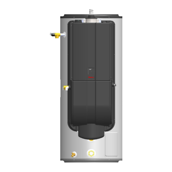
Page 7: Dimensions And Connections
Dimensions and Connections Measurements in inches (in.) LEFT RIGHT FRONT Rinnai Commercial Hybrid System Installation and Operation Manual... -
Page 8: Installation
Gas sizing; Connecting gas lines, water lines, valves, and electricity; Knowledge of applicable national, state, and local codes; Installing venting through a wall or roof; and training in installation of tankless water heaters. Training for Rinnai Tankless Water Heaters is accessible online at www.trainingevents.rinnai.us. Installation Guidelines When installing the Demand Duo™, follow these guidelines:... -
Page 9: Typical Installation Illustrations
Gas Control Valve Gas Union Drip Leg (Sediment Trap) Cold Water Supply Valve Cold Water Supply Thermal Expansion Tank Non-Tempered Supply Line Thermostatic Mixing Valve Non-Tempered Return Line Field Supplied Rinnai Commercial Hybrid System Installation and Operation Manual... -
Page 10: Unpack The Demand Duo
• PVC glue/cement and primer • 2 conductor 22 AWG wire for controller • Single gang electrical box • Wire nuts • Unions and drain valves • Drain pan • Earthquake strap Rinnai Commercial Hybrid System Installation and Operation Manual... -
Page 11: Choose An Installation Location
Water Quality Guidelines This section provides information on the importance of water quality to the Rinnai Tankless Water Heater. The information is intended to serve as general guidelines only and is not a complete list of water quality guidelines. - Page 12 * Clearance for servicing is 24 in. (610 mm) in front of water heater Back 0 in. Sides (Left and Right) 0 in. 0 in. Minimum 0 in. Minimum ** 12 in. Minimum 0 in. Minimum Door *6 in. Minimum Rinnai Commercial Hybrid System Installation and Operation Manual...
-
Page 13: Transporting The Demand Duo
5. Replace the screws around the perimeter of the plastic enclosures. Strap A Plastic STRAP Enclosure (Side) Lower Enclosure STRAP Strap B Plastic Enclosure (Bottom) Rinnai Commercial Hybrid System Installation and Operation Manual... -
Page 14: Installation Location Checklist
The installation must conform with local codes or, in the absence of local codes, with the National Fuel Gas □ Code, ANSI Z223.1/NFPA 54, or the Natural Gas and Propane Installation Code, CSA B149.1. Rinnai Commercial Hybrid System Installation and Operation Manual... -
Page 15: Venting
If it becomes necessary to NOTICE access an enclosed vent system for service or repairs, Rinnai is not responsible for any costs or difficulties in accessing the vent system. The warranty does not cover obtaining access to a vent system in an enclosed environment. -
Page 16: Venting Installation Sequence
• Where condensate or vapor could cause damage or could be detrimental to the operation of regulators pressure relief valves, or other equipment. Rinnai Commercial Hybrid System Installation and Operation Manual... -
Page 17: Select A Vent Type
Exhaust Exhaust Combustion Air Room Air For Combustion Rinnai Commercial Hybrid System Installation and Operation Manual... - Page 18 (Dégagement conforme aux codes d’installation locaux et aux exigences du foumisseur de gaz.) [2] Permitted only if veranda, porch, deck, or balcony is fully open on a mini- mum of two sides beneath the floor. Rinnai Commercial Hybrid System Installation and Operation Manual...
- Page 19 60 in. (1.52 m) vertically 12 in. (0.30 m) between terminals Inside Corner Between terminals at same level All terminations (horizontal and/or vertical) must terminate 12 in. (0.30 m) above grade or anticipated snow level. Rinnai Commercial Hybrid System Installation and Operation Manual...
- Page 20 Important: Install the venting termination according to the diagrams and instructions in this manual. Slope the venting 1/4 in. per foot toward the appliance according to the vent manufacturer’s installation instructions. Dispose of condensate per local codes. Rinnai Commercial Hybrid System Installation and Operation Manual...
- Page 21 Combustion air termination not permitted in shaded area Horizontal Vent and Combustion Air Piping For illustration purposes only. Listed equivalent length is based on worst case scenario of 3 X 90° elbows or 18 equivalent ft. Rinnai Commercial Hybrid System Installation and Operation Manual...
- Page 22 Exhaust Vent Pipe Install the exhaust vent pipe. Ensure it is properly seated. Supplied Secure the exhaust vent pipe to the exhaust adapter ring with the supplied screw. Rinnai Commercial Hybrid System Installation and Operation Manual...
- Page 23 3 in. (76 mm) Vent Lengths 65 ft (20 m) 150 ft (46 m) • 45° elbow is equivalent to 3 ft (1 m) • 90° elbow is equivalent to 6 ft (1.83 m) Rinnai Commercial Hybrid System Installation and Operation Manual...
- Page 24 (Dégagement conforme aux codes d’installation locaux et aux exigences du foumisseur de gaz.) [2] Permitted only if veranda, porch, deck, or balcony is fully open on a mini- mum of two sides beneath the floor. Rinnai Commercial Hybrid System Installation and Operation Manual...
- Page 25 NOTE: All terminations (horizontal and/or vertical) must terminate 12 in. above grade or anticipated snow level. Exhaust Termination Clearances for Internal (Indoor) Room Air Applications 12 in. 12 in. (0.30 m) 60 in. (1.52 m) vertically between terminals Inside Corner Rinnai Commercial Hybrid System Installation and Operation Manual...
- Page 26 /kW) of total input rating of all appliances in the confined space. Note: If ducts are used, the cross sectional area of the duct must be greater than or equal to the required free area of the openings to which they are connected. Rinnai Commercial Hybrid System Installation and Operation Manual...
- Page 27 Combustion air provided to the appliance should not be taken from any area of the structure that may produce a negative pressure (i.e. exhaust fans, powered ventilation fans). WARNING TO PREVENT POSSIBLE PERSONAL INJURY OR DEATH DUE TO ASPHYXIATION, COMMON VENTING WITH OTHER MANUFACTURER’S INDUCED DRAFT APPLIANCES IS NOT ALLOWED. Rinnai Commercial Hybrid System Installation and Operation Manual...
- Page 28 (Room Air) Exhaust Vent termination per ANSI Z223.1/NFPA 54. For clearances not specified in ANSI Z223.1/NFPA 54, clearances are in accordance with local installation codes and the requirements of the gas supplier. Rinnai Commercial Hybrid System Installation and Operation Manual...
- Page 29 Install the exhaust vent pipe. Ensure it is properly seated. Exhaust Vent Pipe Secure the exhaust vent pipe to the exhaust Supplied adapter ring with the supplied screw. screw Rinnai Commercial Hybrid System Installation and Operation Manual...
- Page 30 65 ft (20 m) 150 ft (46 m) 50 ft (15 m) • 45° elbow is equivalent to 3 ft (1 m) • 90° elbow is equivalent to 6 ft (2 m) Rinnai Commercial Hybrid System Installation and Operation Manual...
- Page 31 (Indoor Units Only. Direct Vent and Non-Direct/Room Air Vent) Common venting allows multiple Rinnai Tankless Water Heaters to share the same vent system. Rinnai water heaters can only be common vented with Schedule 40 PVC/CPVC or with the Rinnai certified common vent system.
- Page 32 Use 10 ft (3 m) as equivalent vent length for 90° elbows. • For use with CU199i internal (indoor) tankless water heaters only. Common Vent Maximum Equivalent Vent Length Rinnai Common Vent System or Schedule 40 PVC/CPVC HEADER DIAMETER Max System 3 in.
- Page 33 CVent Wall Terminal Kit 6 in. 780061 Intake Rain Cap 6 in. 780060 Intake Rain Cap 4 in. 790098 Exhaust Flue Rain Cap 6 in. 790097 Exhaust Flue Rain Cap 4 in. Rinnai Commercial Hybrid System Installation and Operation Manual...
- Page 34 Condensate trap must include a loop that can hold 6 in. (15 cm) of water. See “PVC/CPVC Common Vent Installation” illustration on this page. Rinnai Commercial Hybrid System Installation and Operation Manual...
-
Page 35: System Plumbing
If a relief valve discharges periodically, this may be due operation. to thermal expansion in a closed water supply system. Contact the water supplier or local plumbing inspector on how to correct this situation. Do not plug the relief valve. Rinnai Commercial Hybrid System Installation and Operation Manual... -
Page 36: Piping Diagram For Basic Installations
Condensate must be disposed of according to local codes. Tankless Gas Supply Condensate Drain Line Pipe T&P to Open Drain Cold Water Supply Building Circulation Building Hot Water Pump Return Line (Optional) Rinnai Commercial Hybrid System Installation and Operation Manual... - Page 37 Rinnai Commercial Hybrid System Installation and Operation Manual...
-
Page 38: Connect Water Heater To The Water Supply
This will result in premature failure of the fittings, which is not covered by the warranty. Rinnai Commercial Hybrid System Installation and Operation Manual... -
Page 39: Condensate
• A condensate neutralizer kit, 804000074, is • Use only venting that is approved and identified as available from Rinnai. The kit allows condensate to acceptable for your particular model. flow through neutralizing media that raises the pH • of the condensate to a level that will help prevent Slope the venting toward the appliance according corrosion of the drain and public sewer system. - Page 40 Water Water Level Level • Water heaters have an integrated condensate trap. DO NOT install an external condensate trap. EXTERNAL TRAP NOT REQUIRED CONDENSATE DRAIN (1/2 in. PVC) Rinnai Commercial Hybrid System Installation and Operation Manual...
-
Page 41: Gas Supply
1. Access the gas connections by removing the four (4) plastic rivet screws that attach the lower enclosure to the assembly. Then, slowly remove the lower enclosure. 3/4 in. MNPT Gas Connection on Bottom of Water Heater Lower Enclosure Rinnai Commercial Hybrid System Installation and Operation Manual... - Page 42 CU199 Condensing Tankless Water Heaters. 9. Perform a leak and pressure test prior to operating the water heater. If a leak is detected, do not operate the water heater until the leak is repaired. Rinnai Commercial Hybrid System Installation and Operation Manual...
-
Page 43: Power Supply
The Tankless Water Heater wiring diagram is located on the inside of the water heater front cover. The controller wiring diagram is located on the inside front cover of the controller. B R W G B - Black R - Red W - White G - Green Bl - Blue Rinnai Commercial Hybrid System Installation and Operation Manual... - Page 44 Controller Diagnostics Slow flash indicates Tankless Flow Rate has controller is active with dropped below 2.5 GPM no errors Power supply is working correctly Tank Recovery Pump Activated Rinnai Commercial Hybrid System Installation and Operation Manual...
-
Page 45: Post-Installation Checklist
□ Check the gas lines and connections for leaks. □ Confirm that the gas inlet pressure is within limits. □ Confirm that the water heater is rated for the gas type supplied. Rinnai Commercial Hybrid System Installation and Operation Manual... -
Page 46: Maintenance
This will remove excess sediment from the bottom of the tank. This sediment, if allowed to Cold Water accumulate, will reduce the efficiency and the life of Supply Valve the tank. Drain Valve Rinnai Commercial Hybrid System Installation and Operation Manual... -
Page 47: Appendices
Appendices Service/Maintenance Log Date Service / Maintenance Completed Rinnai Commercial Hybrid System Installation and Operation Manual... -
Page 48: Replacement Parts
Rinnai Commercial Hybrid System Installation and Operation Manual... -
Page 49: Warranty
If Rinnai determines that repair of a product is not possible, Rinnai may replace the product with a comparable product at Rinnai’s sole discretion. - Page 50 Limitation on Warranties No one is authorized to make any other warranties on behalf of Rinnai America Corporation. Except as expressly provided herein, there are no other warranties, expressed or implied, including, but not limited to warranties of merchantability or fitness for a particular purpose, which extend beyond the description of the warranty herein.
-
Page 51: Notes
Notes Rinnai Commercial Hybrid System Installation and Operation Manual... - Page 52 100000571(03) 10/2019...
Need help?
Do you have a question about the Demand Duo CHS199100CUiP and is the answer not in the manual?
Questions and answers