
Related Manuals for Exor eX710G


Summary of Contents for Exor eX710G
- Page 1 User’s Manual for eX700 Series Touchscreen Products eX700 Series Operating Instructions MANUGENEX7xx - Version 2.12 © 2018-2022 EXOR International S.p.A.
- Page 2 “as is” without warranty of any kind. Third-party brands and names are the property of their respective owners. www.exorint.com Software available in these products is based on OpenSource. Visit oss.exorint.net for more details. MANUGENEX7xx - Version 2.12 © 2018-2022 EXOR International S.p.A. - Subject to change without notice...
-
Page 3: Table Of Contents
5.5 Optional plugin module installation procedure 6 Power Supply, Grounding and Shielding 7 Battery 8 Special Instruction for Use 9 Getting Started 10 Unpacking and Packing Instructions MANUGENEX7xx - Version 2.12 © 2018-2022 EXOR International S.p.A. - Subject to change without notice... -
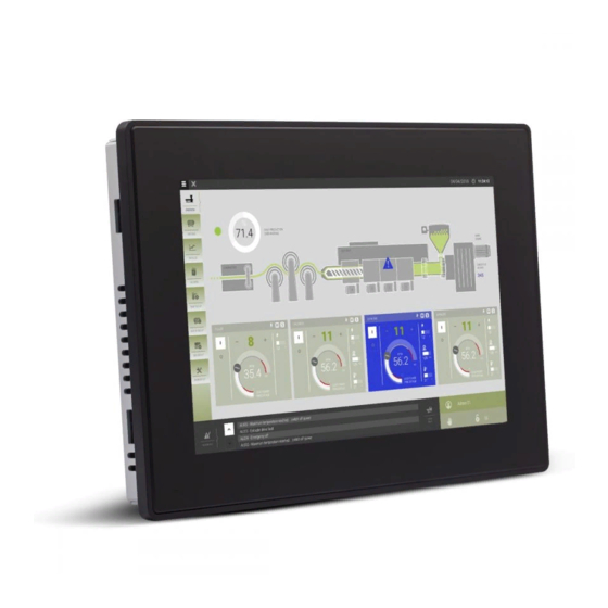
Page 4: Introduction
The operational guidelines described below is information which relates to the device, installation, transpor- tation, storage, assembly, use and maintenance. This Operating Instruction describes the main features of the Exor operator panels. The Manual refers to the following models: eX705 Operator interface with TFT color 5” widescreen display multitouch projected capacitive touchscreen eX707 Operator interface with TFT color 7”... -
Page 5: Safety Guide
ATTENTION: indicates a failure to observe safety rules and that deficiency may cause damage. ATTENTION CAUTION: indicates a failure to observe safety rules and that deficiency may cause defects to the equipment or inconsistencies. CAUTION MANUGENEX7xx - Version 2.12 © 2018-2022 EXOR International S.p.A. - Subject to change without notice... -
Page 6: Product Overview
• Powerful browser wih industry standard Web engines. • Optional CODESYS V3 PLC runtime with choice of major I/O protocols. • Optional plug-in modules for fieldbus systems, I/O and controllers. MANUGENEX7xx - Version 2.12 © 2018-2022 EXOR International S.p.A. - Subject to change without notice... -
Page 7: Standards And Approvals
In compliance with the above regulations the products are CE marked. Products described in this manual may have other approvals and certificates. Please refer to product datasheets available at www.exorint.com MANUGENEX7xx - Version 2.12 © 2018-2022 EXOR International S.p.A. - Subject to change without notice... - Page 8 II 3D Ex tc IIIC T95°C Dc IECEx Marking IECEx: IECEx ULD 17.0019X Ex ec IIC T5...T4 Gc 0°C≤Tamb≤+50°C or -20°C≤Tamb≤+60°C Ex tc IIIC T95°C Dc MANUGENEX7xx - Version 2.12 © 2018-2022 EXOR International S.p.A. - Subject to change without notice...
-
Page 9: Technical Specifications
Immunity to conducted disturbances inducted by radiofrequency field 0.15 ÷ 80 MHz, 10V EN 61000-4-6 Power frequency magnetic field immunity test Enclosure, 50/60Hz, 30A/m EN 61000-4-8 MANUGENEX7xx - Version 2.12 © 2018-2022 EXOR International S.p.A. - Subject to change without notice... - Page 10 12 cycles (60Hz); 70% duration: 25 cycles (50Hz); 30 cycles (60Hz); Phase: 0°-180° Test executed on the 230Vac side of the Exor International S.p.A. Power Supply EN 61000-4-11 Port: DC mains; Level: 0% duration: 10ms 20 spaces by 1s Test executed on the 24Vdc of the EUT...
-
Page 11: Technical Data
For applications requiring compliance with EN 61131-2 and specifically in reference to 10 ms voltage dips (accor- ding to EN 61000-4-29), the lower power supply voltage limit is 20,4Vdc. MANUGENEX7xx - Version 2.12 © 2018-2022 EXOR International S.p.A. - Subject to change without notice... - Page 12 For applications requiring compliance with EN 61131-2 and specifically in reference to 10 ms voltage dips (accor- ding to EN 61000-4-29), the lower power supply voltage limit is 20,4Vdc. MANUGENEX7xx - Version 2.12 © 2018-2022 EXOR International S.p.A. - Subject to change without notice...
- Page 13 For applications requiring compliance with EN 61131-2 and specifically in reference to 10 ms voltage dips (accor- ding to EN 61000-4-29), the lower power supply voltage limit is 20,4Vdc. MANUGENEX7xx - Version 2.12 © 2018-2022 EXOR International S.p.A. - Subject to change without notice...
-
Page 14: Dimensions
4 Technical Data 4.1 Dimensions Cut out MODEL eX705 147mm/5.78” 107mm/4.21” 136mm/5.35” 96mm/3.78” 56mm/2.40” 8mm/0.31” MANUGENEX7xx - Version 2.12 © 2018-2022 EXOR International S.p.A. - Subject to change without notice... - Page 15 271mm/10.67” 186mm/7.32” 56mm/2.20” 8mm/0.31” eX712 344,5mm/13.56” 163mm/6.41” 332,5mm/13,09” 163mm/6,41” 49mm/1,92” 8mm/0,31” eX715 422mm/16.60” 267mm/10.50” 411mm/16.18” 256mm/10.00” 56mm/2.20” 8mm/0.31” eX721 552mm/21.73” 347mm/13.66” 541mm/21.30” 336mm/13.22” 56mm/2.20” 8mm/0.31” MANUGENEX7xx - Version 2.12 © 2018-2022 EXOR International S.p.A. - Subject to change without notice...
-
Page 16: Installation Environment
1,5mm to 6mm max surface roughness where the gasket is applied: O120 um • A. eX7xx B. Installation cut-out MANUGENEX7xx - Version 2.12 © 2018-2022 EXOR International S.p.A. - Subject to change without notice... -
Page 17: Safety Instruction
Place the fixing brackets contained in the fixing kit as shown in figure CAUTION Tightening torque: 130Ncm or screw each fixing screw until the bezel corner gets in contact with the panel. MANUGENEX7xx - Version 2.12 © 2018-2022 EXOR International S.p.A. - Subject to change without notice... -
Page 18: Connections
2. Power Supply 3. Serial port 4. Ethernet Port 0 (10/100Mb) 5. Ethernet Port 1 (10/100Mb) 6. Expansion slot for Plugin module 7. SD Card Slot MANUGENEX7xx - Version 2.12 © 2018-2022 EXOR International S.p.A. - Subject to change without notice... - Page 19 3. Ethernet port 1 (10/100Mb) 4. Serial Port 5. Ethernet port 0 (10/100/1000Mb) 6. Power Supply 7. 2x Expansion slot for Plugin module 8. SD Card Slot MANUGENEX7xx - Version 2.12 © 2018-2022 EXOR International S.p.A. - Subject to change without notice...
-
Page 20: Serial Port
ETH0 > 10/100Mb link > OFF BLINKING: Activity ETH1/2 > 100Mb link > ON ETH1/2 > 10Mb link > OFF On eX705 100Mb link > ON 10Mb link > OFF MANUGENEX7xx - Version 2.12 © 2018-2022 EXOR International S.p.A. - Subject to change without notice... -
Page 21: Optional Plugin Module
• 1 SPI interface • 1 2G/3G interface Note: It is not possible to stack two modules that are using the same type of interface. MANUGENEX7xx - Version 2.12 © 2018-2022 EXOR International S.p.A. - Subject to change without notice... -
Page 22: Optional Plugin Module Identification
1816 serial number AA0000225000000561AA version id of the product 050100A00000000 manufacturer address Exor International S.p.A. Via Monte Fiorino 9 IT-37057 San Giovanni Lupatoto (VR) MANUGENEX7xx - Version 2.12 © 2018-2022 EXOR International S.p.A. - Subject to change without notice... -
Page 23: Optional Plugin Module Installation Procedure
5 Connections 5.5 Optional plugin module installation procedure PLCM PLIO03 MANUGENEX7xx - Version 2.12 © 2018-2022 EXOR International S.p.A. - Subject to change without notice... - Page 24 - PLCM09X: 2xDigital Inputs voltage 12÷30 Vdc, 3mA; 2xDigital Outputs voltage 12÷30 Vdc, 0.5A - PLIO03: 20xDigital Inputs voltage 12÷30 Vdc; 12xDigital Outputs voltage 12÷30 Vdc, 0.5A; 4xAnalog inputs 0÷10 Vdc, 4-20mA; 4xAnalog outputs: 0÷10 Vdc, 4-20mA MANUGENEX7xx - Version 2.12 © 2018-2022 EXOR International S.p.A. - Subject to change without notice...
- Page 25 • a module plugged in Slot#1 or into Slot#2 will be the CanPort 0, • a module plugged in Slot#3 or into Slot#4 will be the CanPort 1. MANUGENEX7xx - Version 2.12 © 2018-2022 EXOR International S.p.A. - Subject to change without notice...
-
Page 26: Power Supply, Grounding And Shielding
The suggested wiring for the power supply is shown below. Fig. 6.2 All the electronic devices in the control system must be properly grounded. Grounding must be performed according to applicable regulations. MANUGENEX7xx - Version 2.12 © 2018-2022 EXOR International S.p.A. - Subject to change without notice... -
Page 27: Battery
Dispose of batteries according to local regulations. ATTENTION This device cannot be disposed of as a domestic waste but according to WEEE European Directive 2012/19/EU MANUGENEX7xx - Version 2.12 © 2018-2022 EXOR International S.p.A. - Subject to change without notice... -
Page 28: Special Instruction For Use
Create an Update Package using JMobile Studio and copy it to a USB Flash drive. Updated product documentation is available at www.exorint.com. For the products described in this manual please check: Systems Settings User Manual JMobile Studio User Manual MANUGENEX7xx - Version 2.12 © 2018-2022 EXOR International S.p.A. - Subject to change without notice... -
Page 29: Unpacking And Packing Instructions
10 Unpacking and Packing Instructions Fig. 11.1: eX705, eX707, eX707G, eX710, eX710G, eX712 Fig. 11.2: eX715, eX721 To repack the unit, please follow the instructions backwards. MANUGENEX7xx - Version 2.12 © 2018-2022 EXOR International S.p.A. - Subject to change without notice...
Need help?
Do you have a question about the eX710G and is the answer not in the manual?
Questions and answers