Exor eTOP 500 Series Operating Instructions Manual
Hide thumbs
Also See for eTOP 500 Series:
- Operating instructions manual (30 pages) ,
- Operating instructions manual (31 pages)

Related Manuals for Exor eTOP 500 Series


Summary of Contents for Exor eTOP 500 Series
- Page 1 Series 500 Glass Operating Instructions Basic User’s Manual for eTOP Series 500 Glass Touchscreen Products Exor International S.p.A. MANUGENETOP5xxG Ver. 1.00...
- Page 2 Copyright © 2015 Exor International S.p.A. – Verona, Italy Subject to change without notice The information contained in this document is provided for informational purposes only. While efforts were made to verify the accuracy of the information contained in this documentation, it is provided “as is” without warranty of any kind.
-
Page 3: Table Of Contents
Table of Contents Table of Contents Introduction Safety Guide 1 Product Overview 2 Standards and Approvals 3 Technical Specifications 4 Technical Data 4.1 Dimensions 4.2 Installation Environment 4.3 Installation Procedure 5 Connections 5.1 Serial Port 5.2 Ethernet Port 5.3 Optional plugin module 6 Power Supply, Grounding and Shielding 7 Battery 8 Cleaning Faceplates... -
Page 4: Introduction
The operational guidelines described below is information which relates to the device, installation, tran- sportation, storage, assembly, use and maintenance. This Operating Instruction describes the main features of the Exor operator panels. The Manual refers to the following models: eTOP507G Operator interface with TFT color 7”... -
Page 5: Safety Guide
Safety Guide Safety Guide The manual contains safety standards that must be respected for the personal safety and to avoid damage. Indications of attention are divided into three levels of severity: DANGER: indicates a failure to observe safety rules and such failure may cause death or serious injuries. DANGER ATTENTION: indicates a failure to observe safety rules and that deficiency may cause damage. -
Page 6: Product Overview
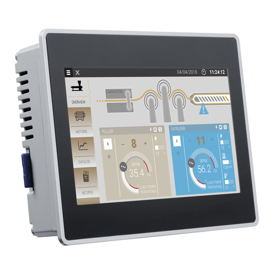
Product Overview 1 Product Overview The Exor eTOP Series 500 Glass HMI products combine state-of-the-art features and top performance with an oustanding design. They are the ideal choice for all demanding HMI applications including factory energy and marine applications. The eTOP Series 500 Glass features a high-brightness, contrast-enhanced ruggedized TFT display with a fully dimmable LED backlight. -
Page 7: Standards And Approvals
Standards and Approvals 2 Standards and Approvals The products have been designed for use in an industrial environment in compliance with the 2004/108/ EC EMC Directive. The products have been designed in compliance with: EN 61000-6-4 EN 55011 Class A EN 61000-6-2 EN 61000-4-2 EN 61000-4-3... - Page 8 Standards and Approvals Product Identification The product may be identified through a plate attached to the rear cover. You will have to know the type of unit you are using for correct usage of the information contained in the guide. An example of this plate is shown in the figure below: eTOP507G product model name...
-
Page 9: Technical Specifications
100% duration: 1 cycle and 250 cycles (50Hz); 40% duration: 10 cycles (50Hz); duration: 25 cycles (50Hz); Phase: 0°-180° Test executed on the 230Vac side of the Exor International S.p.A. Power Supply EN 61000-4-11 Durability information Backlight service life 40000 Hrs. or more... -
Page 10: Technical Data
Technical Data 4 Technical Data Model eTOP507G eTOP507MG Display / Backlight TFT Color / LED TFT Color / LED Colors Resolution 800X480 800X480 Diagonal (inches) 7” widescreen 7” widescreen Dimming User memory flash 128MB 256MB SD card slot Yes. Flash memory storage Yes. - Page 11 Technical Data Model eTOP510G eTOP515G Display / Backlight TFT Color / LED TFT Color / LED Colors Resolution 1280X800 1024X768 Diagonal (inches) 10.1” widescreen 15” Dimming User memory flash 256MB 256MB SD card slot Yes. Flash memory storage Yes. Flash memory storage Recipe memory limited only by available memory limited only by available memory...
-
Page 12: Dimensions
Technical Data 4.1 Dimensions Cut out MODEL eTOP507G 187mm/7.36” 147mm/5.79” 176mm/6.90” 136mm/5.35” 47mm/1.85” 8mm/0.31” eTOP507MG 187mm/7.36” 147mm/5.79” 176mm/6.90” 136mm/5.35” 47mm/1.85” 8mm/0.31” MANUGENETOP5xxG Operating Instructions VER 1.00... - Page 13 Technical Data Cut out MODEL eTOP510G 282mm/11.10” 197mm/7.80” 271mm/10.67” 186mm/7.32” 56mm/2.20” 8mm/0.31” MANUGENETOP5xxG Operating Instructions VER 1.00...
- Page 14 Technical Data Cut out MODEL eTOP515G 392mm/15.43” 307mm/12.08” 381mm/15” 296mm/11.65” 56mm/2.20” 8mm/0.31” MANUGENETOP5xxG Operating Instructions VER 1.00...
-
Page 15: Installation Environment
Technical Data 4.2 Installation Environment Avoid prolonged exposition to direct sunlight to avoid the risk of overheating the device. The equipment is not intended for installation in contact with corrosive chemical compounds. Check the resistance of the front panel to a specific compound before installation. Do not use tools of any kind (screwdrivers, etc.) to operate the touch screen of the panel. -
Page 16: Safety Instruction
Technical Data 4.3 Installation Procedure Place the fixing brackets as shown in figure. CAUTION Screw each fixing screw until the bezel corner gets in contact with the panel. MANUGENETOP5xxG Operating Instructions VER 1.00... -
Page 17: Connections
Connections 5 Connections eTOP507G, eTOP507MG 1. Serial Port 2. 2x Ethernet Port 3. USB Port (version 2.0 - 1.1) 4. USB Port (version 2.0 High speed only) 5. Power Supply 6. Expansion slot for Plugin module 7. SD Card Slot MANUGENETOP5xxG Operating Instructions VER 1.00... - Page 18 Connections eTOP510G, eTOP515G 1. Serial Port 2. 2x Ethernet Port 3. USB Port (version 2.0 - 1.1) 4. USB Port (version 2.0 High speed only) 5. Power Supply 6. Expansion slot for Plugin module 7. SD Card Slot MANUGENETOP5xxG Operating Instructions VER 1.00...
-
Page 19: Serial Port
Connections 5.1 Serial Port The serial port is used to communicate with the PLC or with another type of controller. Different electrical standards are available for the signals in the PLC port connector: RS-232, RS-422, RS-485. The serial port is software programmable. Make sure you select the appropriate interface in the programming software. -
Page 20: Optional Plugin Module
Connections 5.2 Ethernet Port The Ethernet port have two status indicators. Please see description in figure. OFF: Valid link has NOT been detected ON: No activity ON: Valid link has been detected BLINKING: Activity MANUGENETOP5xxG Operating Instructions VER 1.00... - Page 21 Connections 5.3 Optional plugin module eTOP500 Glass Series have several optional plugin module, multiple modules configurations are possible. Slot#2 and Slot#4 are available only if plugin module has the “bus extension connector”. Each slot carries three communication channels: • 1 serial interface •...
- Page 22 Connections Below you can find relation between modules and max number of modules that can be used into eTOP500 Glass serie panels, based on their Interface Type: Module Application Max Modules Interface Type Bus Extension connector PLCM01 1 for eTOP507G 2 for eTOP507MG PLCM01-NE 1 for eTOP507G...
- Page 23 Power Supply, Grounding and Shielding 6 Power Supply, Grounding and Shielding The power supply terminal block is shown in the figure below. Fig. 6.1 Note: Ensure that the power supply has enough power capacity for the operation of the equipment. The unit must always be grounded to earth.
-
Page 24: Optional Plugin Module Installation Procedure
Battery 7 Battery These devices are equipped with rechargeable Lithium battery, not user-replaceable. The following information is maintained by the battery: • hardware real-time clock (date and time) Charge: At first installation must be charged for 48 hours. When the battery is fully charged, it ensures a period of 3 months of data back-up at 25°C. Battery ATTENTION Dispose of batteries according to local regulations. -
Page 25: Power Supply, Grounding And Shielding
Cleaning Faceplates / Getting Started 8 Cleaning Faceplates The equipment must be cleaned only with a soft cloth and neutral soap product. Do not use solvents. 9 Getting Started eTOP Series 500 Glass HMI products must be programmed with the software JMobile Studio. JMobile Studio is a software tool that must be properly installed on a computer running Microsoft Windows. -
Page 26: Battery
System Settings 10 System Settings eTOP Series 500 Glass HMI products have a System Settings tool to allow configuration of system options. The user interface of System Settings tool is based on a rotating menu. Use navigation buttons Next/ Back to scroll through the available options. The active item is highlighted on the left side. -
Page 27: Cleaning Faceplates
System Settings Activation of Systems Settings in System Mode: During normal operation If JMobile runtime is not running: Press “System Settings” button on the HMI screen. If JMobile runtime is running: recall context menu, select “System Settings” Select the Restart option then choose the “Configuration OS” option. Note: To recall the context menu click and hold any unused area of the touchscreen for a few seconds. -
Page 28: System Settings
System Settings Resize Image Area reserved to authorized technical personnel Download Configuration OS update the Configuration OS module of BSP Download Main OS update the Main OS module of BSP Download Splash Image replace the splash screen image displayed by the device at power- up;... - Page 29 Unpacking and Packing Instructions Unpacking and Packing Instructions to repack the unit, please follow the instructions backwards. MANUGENETOP5xxG Operating Instructions VER 1.00...
Need help?
Do you have a question about the eTOP 500 Series and is the answer not in the manual?
Questions and answers