Table of Contents
Advertisement
Quick Links
Advertisement
Table of Contents
Troubleshooting

Related Manuals for KVM-TEC 6701i


Summary of Contents for KVM-TEC 6701i
- Page 1 USER-MANUAL MATRIXLINE FIBER MX-F 6811L CPU/LOCAL 6811R CON/REMOTE Industryline smart connections Industryline MVX-i 6701i SET 6701iL CPU/LOCAL 6701iR CON/REMOTE Industryline fiber MVXi-F 6801 SET 6801iL CPU/LOCAL 6801iR CON/REMOTE Check out our Installation Channel:...
-
Page 2: Table Of Contents
2.2.1 Mounting pads and rubber feet 2.2.2 Mounting kits (optional) 2.3 Installing the extender 2.4 Startup 2.5 Replacing the SFP module 2.6 Removing a CATx cable 2.7 Removing a fiber cable 3.1 How to access the main menu 3.2 Status Menu 2 | kvm-tec... - Page 3 3.9.4 How to show the last received image 3.9.5 How to turn on or off monitor synchronization 3.9.6 How to lock the main menu 3.9.7 How to use power saving mode 3.9.8 How to select your type of keyboard kvm-tec | 3...
- Page 4 4.9 How to set up a private connection 4.10 How to enable the User-PC Binding mode 4.11 How to enable the disconnect on PC Power Down option 4.12 How to hide info display 4.13 How to reconnect on startup 4 | kvm-tec...
- Page 5 10. Declaration of Conformity 11.1 Requirements for CAT5e/6/7 cables 11. Requirements for cables 11.3 Requirements network switch 11.2 Requirements fibER cables 11.2.1 Multi-Mode (standard) 11.2.2 Single-Mode (optional) 12. Requirements Network Switch 13. First Aid 14. Extended warranty 15. Notes kvm-tec | 5...
-
Page 6: Introduction
In these user instructions the Industryline MVXi/MVXi-F KVM Extender is referred to as ‘product’ or ‘extender‘. The MVXi/PC is referred to as the ‘local unit’ and the MVXi/Monitor is referred to as the ‘remote unit‘. 6 | kvm-tec... -
Page 7: Safety Instructions
Do not use other adapters. • Prior to connecting to the mains, make sure your local mains voltage matches the rating indicated on the product. • The product must be connected to a permanent and earthed AC wall socket. kvm-tec | 7... - Page 8 Unplug all connections before cleaning the product. Do not use wipes or chemicals as these could damage the surface. Wipe the housing with a damp cloth. Electrical/ electronic parts must not be cleaned. • Alterations to the product and technical modifications are not permitted. 8 | kvm-tec...
-
Page 9: Technical Specifications
97,5 x 41 x 103,5 mm / 3.83x 1.57 x 4.7 inch ” Weight: local unit 302g/0.66lbs. remote 291g/0.64lbs Expected product life: 82 820 hours / 9.5 years Laser MVX1-F: Class 1 Laser Product 1 according to DIN 40008/EN and VDE 0837 kvm-tec | 9... -
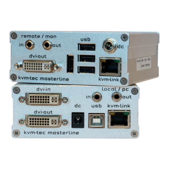
Page 10: Product Elements
DVI connection to PC DC in Connection power supply 12-24V kvm-link/ RJ45 socket Connection for CAT5/6/7 cable or fibre cable USB connection ground screw dvi-out DVI connection to monitor Power/Status LED Display the status of the Extender 10 | kvm-tec... - Page 11 Name Function DC in connection power 12-24V USb connectionfor keyboard and mouse ground screw kvm-link/ RJ45 socket Connection for CAT5/6/7 cable or fibre cable dvi-out DVI-D connection to monitor Power/Status LED Displays the status of the extender kvm-tec | 11...
-
Page 12: Meaning Of Led Indicators
Fast Update in Progress Green Update Succedded Green V. fast Yes** Red/Green V. fast RJ45 Socket LEDs * Yellow Yellow Slow Green Green V. fast * MVX only ** Rem. Only Table 1: Meaning of LED indicators 12 | kvm-tec... -
Page 13: Installation Of The Extender
4 x mounting pads REMOTE UNIT/CON 1 x Power Connector 4 x rubber feet 4 x mounting pads INDUSTRYLINE FIBER 2 x SFP Modul-Multimode up to 500m / 1640 ft. (alternativ with Single-Mode up to 20km / 12 mi) kvm-tec | 13... -
Page 14: Mounting Options
The following mounting kits are available: Rack Mounting Kit RMK-F - Part No. 6130 The rack mounting kit RMK-F is for mounting kvm-tec Industryline MVXi Extender. It consists of a19“ rack shelf and an alu-faceplate. Rack Mounting Kit RMK-FN - Part No. 6131 The rack mounting kit RMK-FN is for assembling kvm-tec Industryline MVXi Extender. -
Page 15: Installing The Extender
In the case of the latter, an additional Network Switch must be installed. With a Network Switch, each user can gain quick access to any of the required computers. point to point connection Set up for Switching System up to 48 endpoint Set up for Switching Systgem up to 48 endpoints kvm-tec | 15... - Page 16 2. INSTALLATION OF THE EXTENDER 2. USB from Kayboard and Mouse 2. USB to PC 4. DVI out 4. DVI in from Monitor from PC 16 | kvm-tec...
- Page 17 HDMI socket of the CPU / Local Unit (PC-in). Then connect the monitor with the HDMI-DVI cable to the CON / Remote Unit. HAVE FUN - your kvm-tec Extender is now in use for many years ( MTBF approx 10 years)
- Page 18 2. INSTALLATION OF THE EXTENDER 2. USB from Kayboard and Mouse 2. USB to PC 4. DVI out 4. DVI in from Monitor from PC 18 | kvm-tec...
- Page 19 HDMI socket of the CPU / Local Unit (PC-in). Then connect the moni- tor with the HDMI-DVI cable to the CON / Remote Unit. HAVE FUN - your kvm-tec Extender is now in use for many years ( MTBF approx 10 years) kvm-tec | 19...
-
Page 20: Startup
2. Pull the metal latch of the SFP module forwards until it is at a right angle. 3. Replace the SFP module with the other module. Put the metal latch back in position. Only use SFP modules from kvm-tec, or recommended by kvm-tec. 20 | kvm-tec... -
Page 21: Removing A Catx Cable
To remove a CATx cable: • Press the latch down and slowly pull the cable out. 2.7 REMOVING A FIBER CABLE To remove a fiber cable: • Press the latch down and slowly pull the cable out. kvm-tec | 21... -
Page 22: How To Access The Main Menu
M Option Overview Overview of all upgrades DDC Option DDC Option Fixed ice position 1020 x 1080 W Network Settings Network Settings G ExtenderSettings Settings Extender Switching List List of all extenders in the switching system Exit Exit 22 | kvm-tec... -
Page 23: Status Menu
The enabled options and the current FW-version is displayed in the left top corner. Link status shows whether there is a physical connection available. Connection indicates if kvm data is currently able to be transmitted. Video and USB show if data is currently being transmitted. kvm-tec | 23... -
Page 24: How Determine The Current Firmware Version
3. EXTENDER MENU/SETTINGS 3.3 HOW DETERMINE THE CURRENT FIRMWARE VERSION To view the firmware version: • Make sure the main menu is open. The currently installed firmware versions of the remote and local units are displayed below (e.g. ‘4267’) 24 | kvm-tec... -
Page 25: How To Perform A Firmware Update
3. EXTENDER MENU/SETTINGS 3.4 HOW TO PERFORM A FIRMWARE UPDATE The latest version of the firmware can be downloaded from http://www.kvm-tec.com/en/ support/firmware-download.html. Each update file is accompanied by a detailed description of the update process. There are four ways to perform an update:... -
Page 26: Update Via A Bitmap Image
The file will be output from an image and will be copied and storede to the currently connected extenders. Wait until all 3 phases of the update have been completed and make sure that you have Never unplug or plug in the devices during the update. 26 | kvm-tec... -
Page 27: Update With Usb Stick
2. copy the update file ( ending in .kvm) to the USB stick 3. make sure that the update file is directly on the stick and that it is not in any subdirectory 4. the USB stick must be formatted with FAT-32 kvm-tec | 27... - Page 28 3. EXTENDER MENU/SETTINGS Plug in the USB stick and wait for a moment 28 | kvm-tec...
- Page 29 3. EXTENDER MENU/SETTINGS Wait until all 4 phases have been completed. kvm-tec | 29...
-
Page 30: Performing Autoupdate
You can select in the menu which part should be updated. As soon as the devices are connected, the firmware is copied from one unit to the other. The flashing of the LEDs indicates that the update process has been completed ( the LEDs are then green) 30 | kvm-tec... -
Page 31: Performing Network Update
The information is then sent to the marked units. During this process the devices can still be in operation. As soon as all updates have been transmitted, the marked devices can be restarted and start with the new firmware. kvm-tec | 31... -
Page 32: Unlock An Upgrade
The information is then sent to the marked units. During this process the devices can still be in operation. As soon as all updates have been transmitted, the marked devices can be restarted and start with the new firmware. 32 | kvm-tec... -
Page 33: How To Enable Or Disable The Usb Memory Upgrade
2. Press the M key. The Options Overview menu opens. The current USB Memory status is displayed (Enabled or Disabled). 3. Press 1 to enable or 0 to disable the USB Memory upgrade The kvm-tec feature „USB save“ prevents the intrusion of viruses via the USB interface. by deactivating mass storage devices. kvm-tec | 33... -
Page 34: How To Define What Ddc Information By The Pc
• Press 4 through 8 to use a predefined resolution which is saved. 3. Press ESC to go back to the main menu. 3.8 HOW TO CHANGE THE NETWORK SETTINGS See chapter „Switching Menu Settings“. 34 | kvm-tec... -
Page 35: How To Change The Extender Settings
To access the Extender Settings menu: 1. Make sure the main menu is open. 2. Press the G key. The Extender Settings menu appears. 3. The extender settings are distributed across two sub-menus: Remote Settings and Local Settings. kvm-tec | 35... - Page 36 3. EXTENDER MENU/SETTINGS 4. To access the local or remote extender settings: • Press the L key to access the Local Settings menu. • Press the R key to access the Remote Settings menu. 36 | kvm-tec...
-
Page 37: How To Optimize Vga Preferences
• Press K for automatic adjustment and positioning of the image area. • Press I to reset parameters to default values. • Press S to save the settings and exit the menu. • Press Q to exit without saving. kvm-tec | 37... -
Page 38: How To Enable Or Disable The Usb Compatibility Mode
The USB compatibility mode can be enables or disabled. To enable/disable the USB compatibility mode: 1. From the Extender Settings menu, press the L key. The Local Settings menu appears. 2. Press the U key to enable or disable the USB compatibility mode. 38 | kvm-tec... -
Page 39: How To Set The Baud Rate For The Rs232
1. From the Extender Settings menu, press the R key. The Remote Settings menu appears. 2. Press the R key. The Baud Rate menu appears. 3. To select a baud rate press the applicable key. The Enter Parity menu opens. 4. To select a parity rate press the applicable key. kvm-tec | 39... - Page 40 The baud rate can be set in the menu. There is a universal setting for baud rates up to 9600 which transmits all different RS232 configurations transparently. For higher baud rates the following settings are available via the menu: Baudrate Parity Stopbits 4800 9600 19200 Even 38400 Mark 57600 Space 115200 230400 40 | kvm-tec...
-
Page 41: How To Show The Last Received Image
1. In the Extender Settings menu, press the R button. The Remote Settings menu becomes Press S to activate or deactivate the function. 2. press S to activate or deactivate the function. 3. press ESC to return to the main menu. kvm-tec | 41... -
Page 42: How To Turn On Or Off Monitor Synchronization
To turn on monitor synchronization: 1. From the Extender Settings menu, press the R key. The Remote Settings menu appears. 2. Press the I key to enable or disable the function. 3. Press ESC to go back to the main menu. 42 | kvm-tec... -
Page 43: How To Lock The Main Menu
The extender menu can be locked. When enabled, the extender locks 5 minutes after start up to prevent unauthorized access. To lock or unlock the menu: 1. From the Extender Settings menu, press the R key. The Remote Settings menu appears. 2. Press the L key. The Menu Lock Menu appears. kvm-tec | 43... -
Page 44: How To Use Power Saving Mode
1. From the Extender Settings menu, press the R key. The Remote Settings menu appears. 2. Press the P key to enable or disable the power saving mode. 3. When in power saving mode, press any key to return to the menu. 44 | kvm-tec... -
Page 45: How To Select Your Type Of Keyboard
1. From the Extender Settings menu, press the R key. The Remote Settings menu appears. 2. Press the K key. The Keyboard Locale menu opens: • Press E to select English (QWERTY) • Press D to select German (QWERTZ) • Press F to select French (AZERTY) kvm-tec | 45... -
Page 46: 9How To Change The Keyboard Fallback Mode
To change the keyboard fallback mode: 1. From the Extender Settings menu, press the R key. The Remote Settings menu appears. 2. Press the O key to change the keyboard fallback mode to 0, 1 or 2. 46 | kvm-tec... -
Page 47: How To Change Keyboard Hortcuts
• Press a single key. Edit the frequency with left and right arrows. - OR - • Press a key combination 3.9.11 HOW TO CLOSE THE EXTENDER SETTINGS MENU To close the Extender Settings menu: • Press Q to close the Extender Settings menu. kvm-tec | 47... -
Page 48: How To Switch Between Different Computers
• If the password system is active, the user currently logged in is displayed at the bottom. You can manually logout by pressing the “x” key or disconnect from the current PC by pressing the „d“ key. 48 | kvm-tec... -
Page 49: How To Share Videos
If the selected local extender currently isn‘t connected, a regular connection including USB, etc. is established. kvm-tec | 49... - Page 50 3. EXTENDER MENU/SETTINGS Videosharing 50 | kvm-tec...
-
Page 51: Network Settings
To access the Network Settings menu (Master View and Network Mode): 1. Make sure the main menu is open (see chapter „How to access the main menu“) 2. Press the W key. The Enter User/Password window opens. kvm-tec | 51... - Page 52 You may have more than one selected depending on their function. Some modes require others, and others are incompatible with each other, but the system will automatically recognise this for you. Press the M key to access the Network Mode menu. 52 | kvm-tec...
-
Page 53: How To Force Disconnect Or Select A Workstation From The Current Connected Devices
To force disconnect or select a workstation from the current connected devices: 1. Make sure the Master View menu is open (see chapter „How to access the Network Settings menu (Master View and Network Mode)”). kvm-tec | 53... - Page 54 • Press the D key to force disconnect the selected device/connection. • Press the E key or Enter key to select a PC or workstation to create or break a connection to that unit. • Press the Q key to exit. 54 | kvm-tec...
-
Page 55: How To Manage User Details,Rights And Groups
To manage user details, rights and groups: 1. Make sure the Master View menu is open (see chapter „How to access the Network Settings menu (Master View and Network Mode)”). 2. Press O to exit the menu. kvm-tec | 55... - Page 56 2. Press the U key. The User List menu opens. • Press the A key to add a new user. • Press the R key to delete the selected user. • Press the I key to display details about the selected user which may be edited. 56 | kvm-tec...
- Page 57 Admins and private connections can’t be interrupted. • User: In the case that a User interrupts the connection of another User, the interrupted User may reclaim the original connection. Admins, Masters and private connections can’t be interrupted. kvm-tec | 57...
-
Page 58: How To View The Status Of All Remote Units
The Console Extender List allows you to view all remote units in the switching network and their current status. To view the status of all remote extenders: 1. Make sure the Master View menu is open (see chapter „How to access the Network Settings menu (Master View and Network Mode)”). 58 | kvm-tec... - Page 59 • “free” indicates that this extender is not busy. 3. To edit the name of an extender, press the I key. The Console Extender Detail menu opens. 4. Press the E key to edit the name of the extender. kvm-tec | 59...
-
Page 60: How To View The Status Of All Local Units
To view the status of all local units: 1. Make sure the Master View menu is open (see chapter „How to access the Network Settings menu (Master View and Network Mode)”). 2. Press the P key. The PC Extender List menu opens. 60 | kvm-tec... - Page 61 Team A PC: Group 2 Team B PC: Group 3 Alex, Blair and Charlie are assigned to be members of Group 1 and Group 2. Danny, Em and Frankie are assigned to be members of Group 1 and Group 3. kvm-tec | 61...
-
Page 62: How To Set Up Dual-Head Or Multi-Head Systems
To group individual local and remote extenders: 1. Make sure the Master View menu is open (see chapter „How to access the Network Settings menu (Master View and Network Mode)“). 2. Press the M key. The Multi-Head configuration menu opens. 62 | kvm-tec... - Page 63 4. Press the A key to add individual extenders. The extender type is automatically determined once the first extender has been selected. 5. Press the E key to edit the multi-head set name of max. 16 characters. kvm-tec | 63...
-
Page 64: How To Enable User Groups And Rights And Login Access
To enable the password option: 1. Make sure the Network Mode menu is open (see chapter „How to access the Network Settings menu (Master View and Network Mode)”). 2. Press the P key to disable or enable the option. 64 | kvm-tec... -
Page 65: How To Auto-Connect To A Free Computer After An Interruption
To enable the auto-connect option: 1. Make sure the Network Mode menu is open (see chapter „How to access the switching menu Master View and Network Mode“). 2. Press the C key to disable or enable the option. kvm-tec | 65... -
Page 66: How To Set Up A Private Connection
2. Press the V key to disable or enable the option. 3. To establish a private connection hold down Shift while you select a new connection (either in the switching menu or by pressing the hot-key combination (see chapter „How to switch between different computers“). 66 | kvm-tec... -
Page 67: How To Enable The User-Pc Binding Mode
To enable the User-PC Binding mode: 1. Make sure the Network Mode menu is open (see chapter „How to access the switching menu Master View and Network Mode“). 2. Press the B key to disable or enable the option. kvm-tec | 67... -
Page 68: How To Enable The Disconnect On Pc Power Down Option
To enable the PC Power Down option: 1. Make sure the Network Mode menu is open (see chapter „How to access the switching menu Master View and Network Mode“). 2. Press the D key to disable or enable the option. 68 | kvm-tec... -
Page 69: How To Hide Info Display
To hide the info display during startup: 1. Make sure the Network Mode menu is open (see chapter „How to access the switching menu Master View and Network Mode“). 2. Press the H key to disable or enable the option. kvm-tec | 69... -
Page 70: How To Reconnect On Startup
1. Make sure the Network Mode menu is open (see chapter „How to access the switching menu Master View and Network Mode“). 2. Press the T key to disable or enable the option. 4.14 VIDEO SHARING See chapter „How to share videos“. 70 | kvm-tec... -
Page 71: How To Set The Password Timeout
See chapter „How to switch between different computers“. • T – Time in min: You define the number of minutes since the last switch before the user and password details are required again to switch. kvm-tec | 71... -
Page 72: Maintenance And Care
Install current firmware from our homepage www.kvm- green has an incorrect tec.com/support display LED is blinking Different firmware Please contact the kvm-tec support team via e-mail: green or USB is not support@kvm-tec.com or by phone: +43 2253 81912 30 compatible 72 | kvm-tec... -
Page 73: Troubleshooting
The packaging is made of environmentally friendly materials, which may be disposed through your local recycling facilities. By disposing of the packaging and packaging waste in the proper manner, you help to avoid possible hazards for the environment and public health. kvm-tec | 73... -
Page 74: Warranty
Austria kvm-tec ASIA-PACIFIC Sales p +9173573 20204 email: sales.apac@kvm-tec.com Phone: 0043 (0) 2253 81 912 kvm-tec China Sales - P + 86 1360 122 8145 email: chin- Fax: 0043 (0) 2253 81 912 99 asales@kvm-tec.com Email: support@kvm-tec.com Web: www.kvm-tec.com Find our newest updates and FAQs on our homepage: http://www.kvm-tec.com/support... -
Page 75: Declaration Of Conformity
10. DECLARATION OF CONFORMITY EU DECLARATION OF CONFORMITY Manufacturer: KVM-TEC Electronic GmbH Gewerbepark Mitterfeld 1A, 2523 Tattendorf, Austria Commercial register number: FN 272328h LG Wr. Neustadt I hereby declare that the device Product: Industryline MVX und MVXi-F Type: MVXi - Digital KVM Extender... - Page 76 EN 61000-3-2:2014 EN 61000-3-3:2013 EN 60950-1:2006+A2:2013, IEC 60950:2005 LASER CLASS 1: EN 60825-1:2007 compatible with IEEE 803.3z Signed for and on behalf of: KVM-TEC Electronic GmbH Place and date of issue: Tattendorf, 2018-05-09 Name, Function, Signature: Ing. Dietmar Pfurtscheller, CEO/Geschäftsführer...
-
Page 77: Requirements For Cat5E/6/7 Cables
Only use shielded installation cable with min. cross section of 24 AWG throughout the length. • The shield should be contiguous and connected to both ends. A shielded patch cable is allowed for connection to the device. Schema EIA/TIA-568 B Color Orange/White Orange Green/White Blue Blue/White Green Brown/White Brown kvm-tec | 77... -
Page 78: Requirements Network Switch
The network switch must fulfil the following specifications: 1 Gigabit Switch, with true port to port transfer rates of 1 Gigabit/second The following switches have all been tested and verified to work with all features of kvm-tec electronic’s Industryline MVXi KVM-extenders. - Page 79 6146 NS24SFP/4SFP+ Network Switch 24x SFP/4x SFP+ 6166 NS48SFP/4SFP+ Network Switch 48 x SFP/4x SFP+ with redundancy power supply 6151 Network Switch 32 x SFP/2x QSFP+ NS32SFP+/2QSFP+ 6161 NS48SFP+/4QSFP+ Network Switch 48x SFP+ 10G / 4x QSFP+ kvm-tec | 79...
-
Page 80: First Aid
Check if other units have ther Unit the same behaviour Contact kvm-tec Contact kvm-tec support support We are here for you to answer your questions about installation? Manual download www.kvm-tec.com kvm-tec Installationchannel on our homepage personally +43 2253 81912 80 | kvm-tec... -
Page 81: Extended Warranty
14. EXTENDED WARRANTY 2 years warrnaty Part nr 9003 Warranty extension to 5 years per set Part nr 9002 Warranty extension to 5 years per uni kvm-tec | 81... -
Page 82: Notes
15. NOTES 82 | kvm-tec... - Page 83 | 83...
Need help?
Do you have a question about the 6701i and is the answer not in the manual?
Questions and answers