Table of Contents
Advertisement
Quick Links
RG79F146H03
ATW INDOOR UNIT OPTIONAL PARTS
2 ZONE KIT
PAC-TZ02-E
● This 2 zone kit MUST be used with Cylinder unit or Hydrobox except for E * SE models.
● Before starting installation, read the following description together with the installation manual included with the Cylinder unit (Hydrobox).
● Please read carefully and observe fully the following safety precautions.
WARNING
Precaution that must be observed to prevent injuries or death.
CAUTION
Incorrect handling could lead to injury or damage to house and household articles.
●
After installation, carry out a test run to ensure correct operation, then explain operation method and safety precautions to the
end user.
Tell your customers to keep this installation manual, and when they give or sell this machine to any other person include this
installation manual with it.
●
If Cylinder unit (Hydrobox) has already been connected to the power supply, ensure circuit breaker is off before carrying out
electrical work.
●
If the 2 zone kit is installed incorrectly or modified after installation by the user, water may leak or 2 zone kit may fall from
Cylinder unit or wall.
●
All installation should be performed by a qualified technician according to local regulations and the instructions given in this
manual.
●
Connections must be made securely and without tension on the terminals.
●
The 2 zone kit must be installed by 2 or more people.
●
All exposed water pipework should be insulated to prevent unnecessary heat loss and condensation.
●
To also use the 2 zone kit in Cooling mode, securely apply heat-insulation to draining pipework. If heat-insulation is
inadequate, condensation could occur on the surface of pipes and dew could drop on the floor or important goods.
●
To prevent dirty water from draining onto the floor next to Cylinder unit or under Hydrobox, please connect appropriate
discharge pipework from the 2 zone kit to its disposal location.
●
Secure 2 zone kit to prevent it from falling.
●
Do not hold piping or drain socket when moving the 2 zone kit.
●
Avoid the connection of piping or drain socket from damage. Otherwise, it may cause water leakage.
●
To prevent incorrect installation, please connect the flexible hose at the bend radius of 150 mm or more.
●
The water flow rate between the Cylinder unit (Hydrobox) and the 2 zone kit must be greater than the total flow rate of Zone1
and Zone2. Otherwise, Zone1 and Zone2 may not be heated properly.
INSTALLATION MANUAL
WARNING
CAUTION
1
Advertisement
Table of Contents

Related Manuals for Mitsubishi Electric RG79F146H03


Summary of Contents for Mitsubishi Electric RG79F146H03
- Page 1 RG79F146H03 ATW INDOOR UNIT OPTIONAL PARTS 2 ZONE KIT PAC-TZ02-E INSTALLATION MANUAL ● This 2 zone kit MUST be used with Cylinder unit or Hydrobox except for E * SE models. ● Before starting installation, read the following description together with the installation manual included with the Cylinder unit (Hydrobox).
-
Page 2: Disposal Of The Unit
2006/66/EC Article 20 Information for end-users and Annex II. Your Mitsubishi Electric heating system products have been manufactured with high quality materials and components which can be recycled and/or reused. The symbol in Figure 1.1 means that electrical and electronic equipment, batter- ies and accumulators at the end of their life, should be disposed of separately from your household waste. -
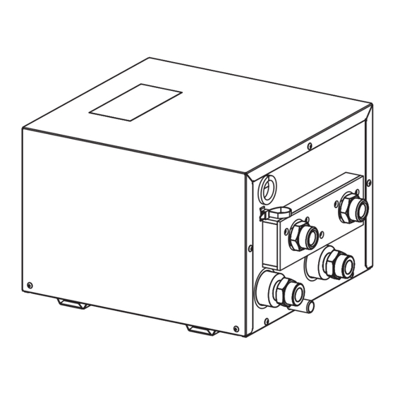
Page 3: Component Parts
Component parts Pump3 Pump2 Mixing valve Thermistor Manual air vent Reactor box Earth terminal Thermistor Installation position Unit: mm <Cylinder unit> <Hydrobox> min300 for service access Water circuit and system fi gure 2 zone kit <Zone2> Cylinder unit Mixing Pump3 Floor heating THW8 valve... - Page 4 In the case of Cylinder unit Ensure that the 2 zone kit does not touch the pressure relief valve. Remove the screw from the 2 zone kit and reuse to secure In the case of Cylinder unit After hand tighten the nut, tighten the joint 1 turn. If necessary, tighten by another 1/4 of a turn.
- Page 5 In the case of Hydrobox Remove the back plate from Install the included the top of the 2-zone kit. back plate accessory. Back plate <Side view> ● Ensure that the notch is positioned at the TOP of the back Back plate plate.
-
Page 6: Drain Piping
In the case of Hydrobox <View from below> Heating only model Heating only model After hand tighten the nut, tighten the joint 1 turn. Heating and cooling model If necessary, tighten by another 1/4 of a turn. Pipe cover Letter Pipe description (Local supply) Space heating/Indirect DHW tank (primary) return connection... - Page 7 Wiring <Cylinder unit> <Hydrobox> Earth terminal TBO.1 TBO.1 CN01 CN01 (BK) (BK) CNP1 CNP1 (WH) CN3C CN3C CNP4 (BU) (BU) TBO.2 (RD) LED1 CNPWM (WH) CNV1 TBO.3 CN851 (WH) (BK) CNRF Pump/ (WH) LED2 THW6/7/8/9 THW6/7/8/9 TBO.4 CN105 LED3 (RD) Mixing valve/ CNIT (BU)
-
Page 8: Specifications
DIP Switch settings of Cylinder unit (Hydrobox) Setting the following DIP switches are necessary for 2 zone control. (See the installation manual of Cylinder unit (Hydrobox) for more information.) DIP switch Function Setting when using 2 zone kit SW2-6 Mixing tank WITHOUT Mixing tank WITH Mixing tank SW2-7 2-zone temperature control... - Page 9 Pump setting selection You can check the setting by pressing the push button. If you press the button for 2 to 10 seconds, the user interface switches to “setting selection” if the user interface is unlocked. You can change the settings as below table. LED1 LED2 LED3...
- Page 10 CP: Constant Pressure The head (pressure) is kept constant, irrespective of the heat demand. CP1: lowest constant pressure curve CP2: intermediate constant pressure curve CP3: highest constant pressure curve CP Auto Adapt: highest to lowest constant pressure curve The Auto Adapt function enables the circulator to adjust the pump performance automatically to the size of the system or the variations in load over time.
- Page 12 Please be sure to put the contact address/telephone number on this manual before handing it to the customer. HEAD OFFICE: TOKYO BUILDING, 2-7-3, MARUNOUCHI, CHIYODA-KU, TOKYO 100-8310, JAPAN Printed in the UNITED KINGDOM...
Need help?
Do you have a question about the RG79F146H03 and is the answer not in the manual?
Questions and answers