Table of Contents
Advertisement
Quick Links
RTKA489206DK0000BU
Evaluation Kit and GUI
This document demonstrates basic operations of the
GUI and RAA489206 Evaluation Kit. Use this
document in the sequence it was written, each
section assumes the previous section was completed.
See the
RAA489206
datasheet for detailed
information.
Software
The RAA489206 Evaluation Board GUI Code zip file
must be downloaded from the Documentation and
Downloads section of the
board page. The RAA489206 GUI is built on top of
Excel using Visual Basic for Applications (VBA 1.00).
It is designed to allow you to perform detailed
evaluation of the RAA489206 and also includes a
simplified demonstration GUI.
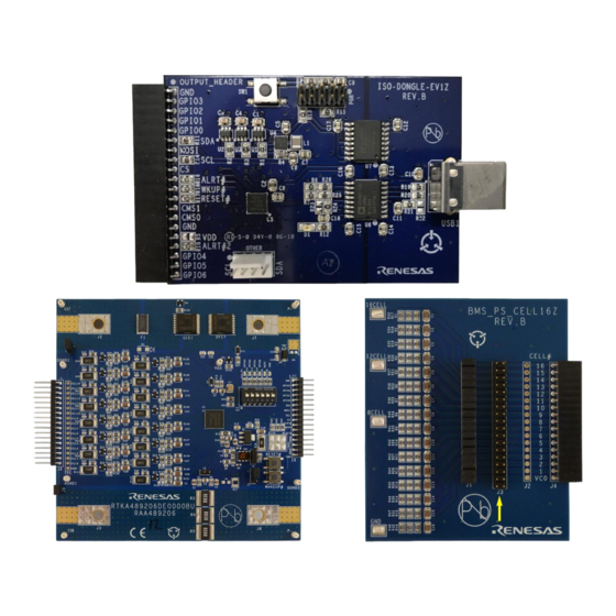
Kit Contents
The RAA489206 Evaluation Kit consists of the
following components:
▪ RTKA489206DE0000BU - RAA489206 eval board
▪ ISO-DONGLE-EV1Z - RAA489206
communications dongle with USB cable
▪ BMS-PS-CELL16Z - A 16-cell resistor ladder board
R16UZ0010EU0100 Rev.1.0
Jun 22, 2021
RTKA489206DK0000BU
Evaluation Kit Manual
Features
▪ High hot plug rating: 62V
▪ V
accuracy: ±5mV
CELL
▪ V
= 55V
BAT
▪ I
accuracy: ±0.2%
PACK
▪ 16-bit V
and I
CELL
PACK
▪ High-side CFET/DFET drivers
▪ Charge/Load wakeup detection circuitry
▪ 4-pin GPIO port
▪ Integrated 3.3V regulator
2
▪ Supports I
C and SPI communications
Recommended Equipment
The following equipment is also needed to complete
an evaluation of the device:
• Power supply (or battery pack)
• Current meter
• Voltmeter
• Oscilloscope
measurements
Page 1
© 2021 Renesas Electronics
Advertisement
Table of Contents

Related Manuals for Renesas RTKA489206DK0000BU


Summary of Contents for Renesas RTKA489206DK0000BU
- Page 1 • Current meter • Voltmeter ▪ RTKA489206DE0000BU - RAA489206 eval board ▪ ISO-DONGLE-EV1Z - RAA489206 • Oscilloscope communications dongle with USB cable ▪ BMS-PS-CELL16Z - A 16-cell resistor ladder board R16UZ0010EU0100 Rev.1.0 Page 1 Jun 22, 2021 © 2021 Renesas Electronics...
- Page 2 RTKA489206DK0000BU Evaluation Kit Manual PACK+ VBAT1 VBAT2 CFET DFET LDMON VC16 GPIO3 CB16 VC15 CB15 GPIO0 RAA489206 V2P5 Battery Front BASE EMITTER CMS0 MISO/SDA PACK- EPAD MOSI THERM AUX1/XT1 ADDR/CS ALRT VTEMP WAKEUP RESET THERM AUX0/XT0 DGND Figure 1. RAA489206 Typical Application R16UZ0010EU0100 Rev.1.0...
-
Page 3: Table Of Contents
RTKA489206DK0000BU Evaluation Kit Manual Contents Functional Description ..............5 Evaluation Board . - Page 4 RTKA489206DK0000BU Evaluation Kit Manual Launching the Demo GUI ............30 Initializing the Demo GUI .
-
Page 5: Functional Description
RTKA489206DK0000BU Evaluation Kit Manual Functional Description Evaluation Board The RAA489206 evaluation board (Figure 2) as shipped from stock is set up for 16 cells with external cell balancing components selected to provide ~500mA of cell balancing current. Figure 2. RAA489206 Evaluation Board (Top) Figure 3. -
Page 6: Evaluation Board Leds
RTKA489206DK0000BU Evaluation Kit Manual Supply current can be monitored by connecting the current meter across J9 or J10. These jumpers MUST be in place if a current meter is not. Exceptions are listed in High Current Loads. The board can be configured for fewer cells by installing jumpers on connector TPC, or across parts of J3 on the... -
Page 7: Evaluation Board Communications Switches
RTKA489206DK0000BU Evaluation Kit Manual Evaluation Board Communications Switches The communication protocol of the RAA489206 is determined by the connection of pin CMS0 (see datasheet). The selection is configured by the jumper J5 in the lower right corner of the evaluation board. With a jumper connecting Pin 2 to Pin 3, the device is configured for I C only. -
Page 8: Resistor Ladder
RTKA489206DK0000BU Evaluation Kit Manual Using the GUI the dongle can be configured to drive or read the RAA489206 GPIO pins. Under some circumstances the dongle draws current from the RAA489206 evaluation board, it might be necessary to disconnect the dongle from the evaluation board if attempting to measure only the current drawn by the RAA489206. -
Page 9: Current Meter
RTKA489206DK0000BU Evaluation Kit Manual Current Meter The current meter is used to measure the current consumed by the RAA489206 Evaluation Board and/or load. If a multimeter is used, make certain it is connected and set to measure current. The current meter should be connected in place of either jumper J9 or J10 on the evaluation board. -
Page 10: 1.11 High Current Loads
Figure 12. GUI Start Press the Launch button to start the GUI. The first time the GUI is launched the Renesas Software License Agreement pop-up opens, select I accept the agreement and click Continue after reviewing it to start the GUI. -
Page 11: Power Supply
RTKA489206DK0000BU Evaluation Kit Manual Launching from the VBA editor can open the Demo GUI. Select the Exit Demo shown in Figure 14 button to close this and open the Evaluation GUI. The use of the Demo GUI is covered later in this document. -
Page 12: Initialization
RTKA489206DK0000BU Evaluation Kit Manual Initialization On startup, the GUI displays for the RAA489206 settings are empty. The RAA489206 has started up in its default configuration (see the RAA489206 datasheet). The displays must be synchronized with the RAA489206 by reading the present values from the device into the displays. After this, a basic initialization is also recommended. -
Page 13: Scan Mode
RTKA489206DK0000BU Evaluation Kit Manual SCAN Mode For normal operation during charging or discharging of the Battery Pack, the RAA489206 should be in SCAN Mode. The system Mode is controlled by the Scan Operation register, shown in Table 1 Table 2. The POR/RESET defaults are highlighted in yellow. -
Page 14: Busy Bit
RTKA489206DK0000BU Evaluation Kit Manual Busy Bit The RAA489206 has a read-only bit that indicates when the device is busy making measurements, Bit 2 of the Global Operations register. The bit is 1 when the device is busy measuring and 0 when idle. The bit value status is inverted and output on the ALRT pin if Mask Register 0x65 Bit 0 is set to 0 (done by Basic Init). -
Page 15: Continuous System Scans
RTKA489206DK0000BU Evaluation Kit Manual Figure 22. Oscilloscope Measurement Results Experiment by disabling all but one Measurement Enable bit to see the busy times for each section. Also, look at the effect on the measurement time of the averaging settings. The capture in... -
Page 16: Low Power Timer
RTKA489206DK0000BU Evaluation Kit Manual register 0x01 and set (check) Bit 0x01.1 Sys Select, then click on the Write button below it. Writing a value of 0x02 to register 0x01 stops the continuous scan. Any changes to settings that are used as controls or thresholds during system scan (single or continuous) must be made when the system scan is STOPPED. -
Page 17: Idle Mode
RTKA489206DK0000BU Evaluation Kit Manual In the 0x2E Scan Operation area on the System tab, set the mode to SCAN, set the Low Power Timer to 512 scans, and the scan delay to 64ms. With these settings, each scan takes ~100ms. If the IPack voltage is between approximately ±200µV for 512 consecutive scans, the device transitions from SCAN to LOW POWER Mode. -
Page 18: Cell Select
RTKA489206DK0000BU Evaluation Kit Manual Figure 26. VCell Measure 4.1.1 Cell Select Cell Select register settings (Figure 27) are found on the System tab of the GUI. Figure 27. Cell Select The Cell Select register sets which and how many cells the RAA489206 manages. If the box (and associated bit) corresponding to a particular cell is 0 and grayed out, that cell is not measured or compared to thresholds. -
Page 19: Vcell Fault Detection
RTKA489206DK0000BU Evaluation Kit Manual 4.1.2 VCell Fault Detection VCell Fault detection threshold register settings (Figure 28) are found on the Voltage tab of the GUI. Figure 28. VCell Thresholds During cell voltage measurement each enabled cell voltage is compared to both overvoltage (0x06) and undervoltage (0x07) threshold registers. -
Page 20: Ipack Trigger
RTKA489206DK0000BU Evaluation Kit Manual compare accomplished during the cell voltage measurement. Trigger another VCell measurement and verify the fault is detected and if the FETs have shut off. Click on the Clear Faults button and note the faults are now cleared. Re-enable the Power FETs by clicking on the red CFET and DFET buttons, they should return to green. - Page 21 RTKA489206DK0000BU Evaluation Kit Manual voltage across the stock current-sense resistor to mimic an overcurrent condition or replace the current-sense resistors with a higher value component so the voltage threshold can be reached with a lower current. Note: The RSense setting in the GUI must match the value of the current sense resistance on the evaluation board for the IPack current displayed on the Meas tab to be correct.
- Page 22 RTKA489206DK0000BU Evaluation Kit Manual 4.2.1.3 DOC Fault Set register 0x0B Discharge Overcurrent threshold to a voltage achievable with your setup while the IPack voltage is below this threshold (less negative). Trigger an IPack measurement then Read the results into the GUI display.
-
Page 23: Vreg Trigger
RTKA489206DK0000BU Evaluation Kit Manual VREG Trigger Select the Meas tab. Select VReg from the drop-down list then press the Trigger Individual button to trigger a regulator voltage measurement. Click Read Measurements and note that only the VCC and IREG voltage... -
Page 24: Ireg Oc2 Threshold
RTKA489206DK0000BU Evaluation Kit Manual Setting LED switches S1 to ON and setting the GPIO pins low (see Figure 84) increases the regulator current. Set the 0x1D IRegOC1 Threshold to its maximum, execute Clear Fault and enable CFET and DFET. 4.3.3... -
Page 25: Vbat1 Ov Threshold
RTKA489206DK0000BU Evaluation Kit Manual 4.4.1 VBAT1 OV Threshold The Vbat1 Overvoltage Threshold register sets the maximum voltage for the VBAT1 pin voltage, exceeding this voltage during charging in SCAN Mode sets the Bit 0x65.7 VBOVF and shuts off the power FETs. -
Page 26: Internal Temperature
RTKA489206DK0000BU Evaluation Kit Manual Trigger another VBAT voltage measurement and read back the results, VBUVF is now set as shown in Figure All Fault and status bits are also viewable on the Status tab. If the device is discharging (DCHRGI is set), CFET and DFET shut off. If running in continuous scan, the scan stops. -
Page 27: Comm Timeout
RTKA489206DK0000BU Evaluation Kit Manual Figure 52. IOTF This is the internal temperature fault bit, if set it shuts off the power FETs and stops continuous system scans. Verify these fault bits are also set on the Status tab. Set register 0x22 IOTW Threshold to about 85° and register 0x23 IOTF Threshold to about 95°. Trigger another internal temperature measurement, then Read Voltages and note the IOTW and IOTF bits remain set. -
Page 28: Low Power Mode
RTKA489206DK0000BU Evaluation Kit Manual LOW POWER Mode Put the device in LOW POWER Mode by selecting LOW PWR from the Mode drop-down menu on the System tab as shown in Figure Figure 55. LP Mode As stated previously, while in this mode the ALRT LED flashes every ~2s while the RAA489206 powers up necessary circuitry to make measurements, then powers down again. -
Page 29: Ship Mode
RTKA489206DK0000BU Evaluation Kit Manual SHIP Mode Put the device in SHIP Mode by selecting SHIP from the Mode drop-down menu on the System tab as shown in Figure Figure 57. SHIP Mode Click on the Read Voltages button and note the results. While in SHIP Mode the IC does nothing but wait for a WAKEUP or a RESET assertion or a change mode command. -
Page 30: Wakeup
RTKA489206DK0000BU Evaluation Kit Manual Wakeup Continuing from the previous section, the RAA489206 should be in SHIP Mode with the weak regulator active. Press the Read Page button on the System tab to read the settings, including the Scan Operation Register. -
Page 31: Initializing The Demo Gui
RTKA489206DK0000BU Evaluation Kit Manual Initializing the Demo GUI After launching the demo GUI, press the Demo Init button on the left side of the GUI as highlighted in Figure This configures the RAA489206 with settings appropriate for demonstration, and reads these settings into the GUI. -
Page 32: Demo Graphing
RTKA489206DK0000BU Evaluation Kit Manual a continuous scan is running. To stop the continuous scan, press the Stop Continuous Scan button shown in Figure Figure 63. Start Continuous Scan Figure 64. Stop Continuous Scan Demo Graphing The demonstration GUI enables graphing of measurements of interest versus time. -
Page 33: Demo Threshold Modification
RTKA489206DK0000BU Evaluation Kit Manual If you wish to look more closely at the data that is used to make the graphs, it can be seen on the Graph Sheet (Figure 67) of the GUI workbook. This data gets erased every time Start Graphing is pressed. -
Page 34: Exiting The Demo Gui
RTKA489206DK0000BU Evaluation Kit Manual Exiting the Demo GUI To return to the evaluation GUI from the demonstration GUI simply press the Exit Demo button in the top left corner of the display. This button is highlighted in Figure Figure 70. Exit Demo R16UZ0010EU0100 Rev.1.0... -
Page 35: Board Design
Board Design Schematic Drawings Figure 71. Eval Board Schematic Sheet 1... - Page 36 Figure 72. Eval Board Schematic Sheet 2...
-
Page 37: Rtka489206De0000Bu Bill Of Materials
RTKA489206DK0000BU Evaluation Kit Manual RTKA489206DE0000BU Bill of Materials Reference Designator Description Manufacturer Manufacturer Part Number PWB-PCB, MTL (Multilayer PCB RTKA489206DE0000BURVAPCB RTKA489206DE0000BU, International) REVA, ROHS C31, C32, C33, C34 CAP-AEC-Q200, SMD, 08051A470K4T4A 0805, 47pF, 100V, 10%, C0G/NP0, ROHS C6, C8 CAP, SMD, 0805, 1µF,... - Page 38 RTKA489206DK0000BU Evaluation Kit Manual Reference Designator Description Manufacturer Manufacturer Part Number D2, D11 DIODE-SCHOTTKY, SMD, Diodes Inc. BAT46W-E3-08 SOD-123, 100V, 0.15A, ROHS D1, D6, D14 LED-SMART, SMD, 0603, Osram LGL29K-G2J1-24-Z GREEN, 1.7V, 2mA, 570nm, 3.9mcd, ROHS D5, D10 LED-SMART, SMD, 0603,...
- Page 39 RTKA489206DK0000BU Evaluation Kit Manual Reference Designator Description Manufacturer Manufacturer Part Number R7, R8, R12, R14, RES, SMD, 0805, 10k, Venkel CR0805-8W-1002FT(PbFREE) R59, R60, R61, R62, 1/8W, 1%, TF, ROHS R63, R89, R90, R91, R92, R93, R109, R110, R111, R127, R128, R129...
-
Page 40: Ordering Information
RTKA489206DK0000BU Evaluation Kit Manual Reference Designator Description Manufacturer Manufacturer Part Number D3 (SMAJ58A) DO NOT POPULATE OR PURCHASE D8 (V15P8-M3) DO NOT POPULATE OR PURCHASE J2, J3, J7, J8 DO NOT POPULATE OR (KPA8CTP) PURCHASE DO NOT POPULATE OR PURCHASE... - Page 41 RTKA489206DK0000BU Evaluation Kit Manual Appendix A The values displayed in the following images are the device settings following Basic Init. • The Reg Map tab (Figure 73) displays the values of all of the user registers in hex • The Read All Reg button reads the registers from the device and updates the GUI with these values.
- Page 42 RTKA489206DK0000BU Evaluation Kit Manual Figure 75. MEAS Tab The Meas tab (Figure 75) allows you to see the RAA489206 measurement results obtained during a system or an individual triggered scan. The IPack current is calculated by dividing the IPack voltage by the RSense resistor value stored on the IPack tab.
- Page 43 RTKA489206DK0000BU Evaluation Kit Manual Figure 76. System Tab The System tab (Figure 76) contains various settings related to overall system behavior. These include which cells are enabled, the Scan and Global operations registers, which measurements are enabled during a scan, Low Power Mode Options, Measure Averaging Options, and how frequently certain values are updated during a continuous scan.
- Page 44 RTKA489206DK0000BU Evaluation Kit Manual Figure 77. Voltage Tab The Voltage tab (Figure 77) allows you to view and change various thresholds and settings related to both Pack and Cell voltage settings. For VPack, you can set the Pack Overvoltage and Undervoltage fault thresholds, and VPack Connect allows you to control if these faults disable the power FETs.
- Page 45 RTKA489206DK0000BU Evaluation Kit Manual Figure 78. IPack Tab The IPack tab (Figure 78) contains various IPack control options. The IPack OC Thresholds section allows you to view and adjust settings related to charge overcurrent and discharge overcurrent conditions. The IPack, DSC, LDMON and WAKE UP Thresholds allow you to adjust other pack current and load detection related settings.
- Page 46 RTKA489206DK0000BU Evaluation Kit Manual Figure 79. ITEMP/Reg Tab The ITemp/Reg tab (Figure 79) allows you to view and modify settings related to the internal temperature fault thresholds and regulator thresholds. The IReg Sense R resistor value is set in this tab, which is used to calculate the IReg current value displayed on the Meas tab.
- Page 47 RTKA489206DK0000BU Evaluation Kit Manual Figure 80. AUX/AUX tab The Aux tab is composed of two sub-tabs related to the external thermistors. The Aux sub-tab (Figure 80) allows you to view and modify various component values related to the thermistors. Figure 81. AUX Thresholds Tab...
- Page 48 RTKA489206DK0000BU Evaluation Kit Manual Figure 82. CB Setup Tab The CB tab is composed of two Cell Balancing related sub-tabs. The Setup sub-tab (Figure 82) allows you to view and adjust various cell balancing related settings. Importantly, this is where the CB Operation register is controlled from. To understand how this register controls Cell Balancing consult the datasheet.
- Page 49 RTKA489206DK0000BU Evaluation Kit Manual Figure 84. GPIO Tab The GPIO tab (Figure 84) allows you to either view or control the status of the RAA489206 GPIO pins, depending on the configuration. The tab also allows you to select from the various GPIO configurations for the device. See the datasheet for the various GPIO configurations and operation.
- Page 50 RTKA489206DK0000BU Evaluation Kit Manual Figure 86. Faults/Status Mask Bits Tab The Mask Bits sub-tab (Figure 86) allows you to view and modify the various mask bits in the device. Writing any of these bits to 0 allows the corresponding fault/status to propagate to the ALRT pin.
- Page 51 RTKA489206DK0000BU Evaluation Kit Manual Figure 87. Dongle Tab The Dongle tab (Figure 87) allows you to view and modify the settings of the ISO-DONGLE-EV1Z communications dongle. R16UZ0010EU0100 Rev.1.0 Page 51 Jun 22, 2021...
- Page 52 Renesas' products are provided only subject to Renesas' Terms and Conditions of Sale or other applicable terms agreed to in writing. No use of any Renesas resources expands or otherwise alters any applicable warranties or warranty disclaimers for these products.
Need help?
Do you have a question about the RTKA489206DK0000BU and is the answer not in the manual?
Questions and answers