Table of Contents
Advertisement
Quick Links
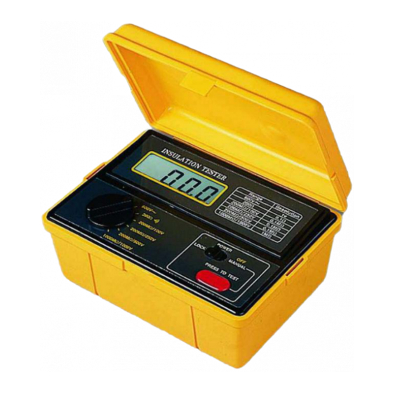
INSULATION TESTE R
Model : AM-2002
Your purchase of this INSULATION TESTER marks a step
forward for you into the field of precision measurement.
Although this INSULAT ION T ESTER is a complex and delicate
instrument, its durable structur e developed. Please read the
following instructions carefully and always keep this manual
within easy reach.
OPERATION MANUAL
www.tmatlantic.com
Advertisement
Table of Contents

Related Manuals for Aktakom AM-2002


Summary of Contents for Aktakom AM-2002
- Page 1 INSULATION TESTE R Model : AM-2002 Your purchase of this INSULATION TESTER marks a step forward for you into the field of precision measurement. Although this INSULAT ION T ESTER is a complex and delicate instrument, its durable structur e developed. Please read the following instructions carefully and always keep this manual within easy reach.
- Page 2 Caution Symbol Caution : * Risk of electric shock ! Caution : * Do not touch the input terminals & the test lead's pins during the measurements. * Mega ohm range, do not apply external voltage to input terminals at any time. * ACV &...
-
Page 3: Table Of Contents
TABLE OF CONTENTS 1. FEATURES............... 1 2. SPECIFICATIONS............1 2-1 General Specifications......... 1 2-2 Electrical Specifications........3 3. FRONT PANEL DESCRIPTION........4 3-1 Display..............4 3-2 Function/Range Switch........4 3-3 Power Lock/Manual(off) Switch......4 3-4 Test Button............4 3-5 Input Terminal..........4 3-6 Battery Cover/Compartment....... 4 4. -
Page 4: Features
1. FEATURES * Digital display, easy and correct read-out. * Multi function for insulation measurement of 200 M ohm(100V) 200 M ohm(250V), 200 M ohm(500V), 1000 M ohm(1000V). * Build in the ACV & OHM measurement function. * Precision 200ohm range easy for measuring low resistance such as motor windings, relay coils etc. - Page 5 Sampling Time 0.4 second. Mega ohm Max. approx. 2.5 second. Respond Time Zero Adjustment Automatic adjustment. Over-input Indication of "1" . Operating Temp. 0 to 50 (0 to 122 ) ℃ ℉ Operating Less than 80% R.H. Humidity Power Supply DC 9V, 1.5V AA(UM-3) battery x 6 PCs.
-
Page 6: Electrical Specifications
2-2 Electrical Specifications (23± 5 ℃ Mega ohm Range Accuracy Resolution Test Voltage 200 M ohm(100V) ± (3%+1d) 0.1 M ohm 100 V (+ 5%) 500 K ohm ≧ 200 M ohm(250V) ± (3%+1d) 0.1 M ohm 250 V (+ 5%) 500 K ohm ≧... -
Page 7: Front Panel Description
2. FRONT PANEL DESCRIPTION Fig. 1 3-1 Display 3-2 Function/Range Switch 3-3 Power Lock/Manual(off) Switch 3-4 Test Button 3-5 Input Terminal 3-6 Battery Cover/Compartment... -
Page 8: Precaution & Preparations For Measurements
4. PRECAUTION & PREPARATIONS FOR MEASUREMENTS 1. Remove the power from the circuit when making the measurement. If any voltage is present in the testing circuit, then an erroneous reading will result. 2. Ensure that the batteries (6 x 1.5 V AA battery) is connected correctly the right position into the battery compartment. -
Page 9: Mega Ohm Measurement(Insulation Measurement)
5-2 Mega OHM Measurement(Insulation Measurement) * Do not touch the input terminals & the test lead's pins during the measurements. * Do not apply external voltage to input terminals at any time. 1. Connect the RED test plug into "Hi terminal"(3-5, Fig. -
Page 10: Power Lock/Manual(Off) Switch
4. Connect test alligator clips into circuit under test. 5. Push the "Test Button"(3-4, Fig. 1) for measurement. 5-4 Power Lock/Manual(off) Switch Typically, when make the general measurement, always slide the "Power Lock/Manual(off) Switch"(3-3, Fig. 1) to the MANUAL(off) position. Then push the "Test Button" will power on the meter until release the "Test Button"(3-4, Fig. -
Page 11: Battery Replacement
2. Measurements made in a humid environment will result in lower insulation resistance values than a dry environment. 7. BATTERY REPLACEMENT * Remove test leads before open the battery cover ! * Risk of electric shock ! 1. When the upper left corner of LCD display show "BAT". It is necessary to replace the battery. -
Page 12: The Address Of After Service Center
8. THE ADDRESS OF AFTER SERVICE CENTER...
Need help?
Do you have a question about the AM-2002 and is the answer not in the manual?
Questions and answers