Table of Contents
Advertisement
Available languages
Available languages
Quick Links
INSTALLATION INSTRUCTIONS
INSTALLATION AND SERVICE MUST BE PERFORMED BY A QUALIFIED
IMPORTANT: SAVE FOR LOCAL ELECTRICAL INSPECTOR'S USE.
READ AND SAVE THESE INSTRUCTIONS FOR FUTURE REFERENCE.
WARNING
FOR YOUR SAFETY: Do not store or use gasoline or other flammable vapors or
liquids near this or any other appliance.
Table of Contents
IMPORTANT SAFETY INSTRUCTIONS........ 2
Product Dimensions ........................................ 3
Cabinet clearances.......................................... 4
Location of the grounded outlet....................... 4
Installing the backguard .................................. 5
Installing the front/side skirting ........................ 5
Installing the door handle ................................ 6
Island installation............................................. 7
Unpacking, moving and positioning the range 7
Electrical connection ....................................... 8
Wall and floor attachment.............................. 10
Door removal................................................. 12
All rights reserved. Printed in Italy
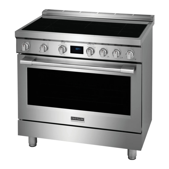
36" INDUCTION RANGE
INSTALLER.
Important Notes to the Installer
1. Read all instructions contained in these installa-
tion instructions before installing the range.
2. Remove all packing materials from the oven and
the drawer compartments before connecting the
electrical supply to the range.
3. Observe all governing codes and ordinances. Be
sure to leave these instructions with the con-
sumer.
Important Note to the Customer
Keep these instructions with your owner's guide for
future reference.
Advertisement
Chapters
Table of Contents

Related Manuals for Frigidaire PCFI3668AF


Summary of Contents for Frigidaire PCFI3668AF
- Page 1 INSTALLATION INSTRUCTIONS 36” INDUCTION RANGE INSTALLATION AND SERVICE MUST BE PERFORMED BY A QUALIFIED INSTALLER. IMPORTANT: SAVE FOR LOCAL ELECTRICAL INSPECTOR'S USE. READ AND SAVE THESE INSTRUCTIONS FOR FUTURE REFERENCE. WARNING FOR YOUR SAFETY: Do not store or use gasoline or other flammable vapors or liquids near this or any other appliance.
- Page 2 36” INDUCTION RANGE INSTALLATION INSTRUCTIONS IMPORTANT SAFETY INSTRUCTIONS This manual contains important safety symbols and • Before installing the range in an area covered instructions. Please pay attention to these symbols with linoleum or any other synthetic floor cov- ering, make sure the floor covering can with- and follow all instructions given.
- Page 3 36” INDUCTION RANGE INSTALLATION INSTRUCTIONS Product Dimensions Tip Over Hazard WARNING • A child or adult could tip the range over and be killed. • Install the anti-tip device on the floor or wall as per the installation instructions. • Engage the range with the anti-tip device as per the installation instructions.
- Page 4 36” INDUCTION RANGE INSTALLATION INSTRUCTIONS Cabinet clearances The side cabinet depth (clearance F) must match the front edge of the range side panel: Location of the grounded outlet 914 mm 36” 603 mm 23” 3/4 178 mm 7” min. 914 mm min.
- Page 5 36” INDUCTION RANGE INSTALLATION INSTRUCTIONS Installing the backguard Installing the front/side skirting The backguard provided is an integral part of the The front skirting must always be correctly posi- appliance; it must always be positioned and secured tioned and secured to the appliance. correctly on the cooktop.
- Page 6 36” INDUCTION RANGE INSTALLATION INSTRUCTIONS Installing the door handle 5. Insert the tabs on the side skirting into the slots on the back of the front skirting. The door handle provided comes unattached to the appliance and must be secured to the oven door during the installation.
- Page 7 36” INDUCTION RANGE INSTALLATION INSTRUCTIONS Island installation The side cabinet depth (clearance A) must match the front edge of the range side panel: If the appliance is installed as an island: 1. Unscrew the screws indicated. 2. Remove the spacers (C). 3.
- Page 8 36” INDUCTION RANGE INSTALLATION INSTRUCTIONS Electrical connection • The anti-tip device must be installed, and the elec- trical connection should be made before the range is placed in its final position. Electrical shock hazard WARNING • Legs should be installed near to where the appli- ance will be used as they are not secure for long •...
- Page 9 36” INDUCTION RANGE INSTALLATION INSTRUCTIONS This range is equipped with a factory-connected power cord. The cord must be connected to a Electrical shock hazard WARNING grounded 120/240 volt or 120/208 volt outlet. If no outlet is available, have one installed by a qualified •...
- Page 10 36” INDUCTION RANGE INSTALLATION INSTRUCTIONS Wall and floor attachment 2. Based on the model, fold the template sheet fol- lowing the horizontal dashed line,. Electrical shock hazard WARNING • Use extreme caution when drilling holes in the wall or floor. There may be con- cealed electrical wiring behind the wall or under the floor.
- Page 11 36” INDUCTION RANGE INSTALLATION INSTRUCTIONS Installing the anti-tip bracket: 5. Use the specified distance from the side of the appliance to the bracket holes. 1. Ensure that the electrical connection is in the correct position. 2. Assemble the bracket. 6. Move the bracket to the wall and fix with the two washers and screws.
- Page 12 36” INDUCTION RANGE INSTALLATION INSTRUCTIONS 7. Use the following distances for the distance from 9. Push the cooker towards the wall, and at the the side of the appliance to the bracket holes. same time, insert the bracket in the plate that is fastened to the rear of the appliance.
-
Page 13: Table Of Contents
INSTALLATION INSTRUCTIONS CUISINIÈRE À INDUCTION 36” L’INSTALLATION ET L’ENTRETIEN DOIVENT ÊTRE EFFECTUÉS PAR UN INSTAL- LATEUR QUALIFIÉ. IMPORTANT : À CONSERVER POUR L’USAGE DES INSPECTEURS DES RÉSEAUX ÉLECTRIQUES LOCAL. LISEZ ET CONSERVEZ CES INSTRUCTIONS À TITRE DE RÉFÉRENCE ULTÉ- RIEURE. AVERTISSEMENT POUR VOTRE SÉCURITÉ... -
Page 14: Consignes De Sécurité Importantes
INSTRUCTIONS D’INSTALLATION CUISINIÈRE À INDUCTION 36” CONSIGNES DE SÉCURITÉ IMPORTANTES Ce manuel contient des instructions et des sym- • Avant d'installer la cuisinière dans une zone recouverte de linoléum ou de tout autre revê- boles de sécurité importants. Veuillez faire attention tement de sol synthétique, assurez-vous que à... -
Page 15: Dimensions Du Produit
INSTRUCTIONS D’INSTALLATION CUISINIÈRE À INDUCTION 36” Dimensions du produit Risque de basculement AVERTISSE- MENT • Un enfant ou une personne adulte pourrait faire basculer la cuisinière et être tué. • Installez le dispositif anti-bas- culement sur le sol ou le mur selon les instructions d'ins- tallation. -
Page 16: Dégagements Des Cabinets
INSTRUCTIONS D’INSTALLATION CUISINIÈRE À INDUCTION 36” Dégagements des cabinets La profondeur du cabinet latéral (dégagement F) doit correspondre au bord avant du panneau latéral de la cuisinière : 914 mm 36” Emplacement de la prise de mise 603 mm 23” 3/4 à... -
Page 17: Installation Du Dosseret
INSTRUCTIONS D’INSTALLATION CUISINIÈRE À INDUCTION 36” Installation du dosseret Installation de la plinthe avant/ latérale Le dosseret fourni fait partie intégrante de l’appareil; il doit toujours être positionné et bien sécurisé sur la La plinthe avant doit toujours être correctement table de cuisson. -
Page 18: Installation De La Poignée De La Porte
INSTRUCTIONS D’INSTALLATION CUISINIÈRE À INDUCTION 36” Installation de la poignée de la 5. Insérez les languettes de la plinthe latérale dans les fentes à l'arrière de la plinthe avant. porte La poignée de la porte fournie n’est pas fixée à l’appareil et doit être fixée à... -
Page 19: Installation De L'îlot
INSTRUCTIONS D’INSTALLATION CUISINIÈRE À INDUCTION 36” Installation de l’îlot La profondeur du cabinet latéral (dégagement A) doit correspondre au bord avant du panneau latéral de la cuisinière : Si l'appareil est installé en tant qu'îlot : 1. Dévissez les vis indiquées. 2. -
Page 20: Branchement Électrique
INSTRUCTIONS D’INSTALLATION CUISINIÈRE À INDUCTION 36” • Le plancher, sous les socles, devrait être protégé Pour avoir une bonne stabilité, il est indispensable (bois, morceau de carton, tapis, lambris, etc.) que l'appareil soit correctement nivelé au sol : avant de positionner la cuisinière. •... - Page 21 INSTRUCTIONS D’INSTALLATION CUISINIÈRE À INDUCTION 36” Cette cuisinière est équipée d'un cordon d'alimenta- tion branché en usine. Le cordon doit être branché à Risque de choc élec- AVERTISSEMENT une prise de 120/240 volts ou 120/208 volts mise à trique la terre. Si aucune prise n'est disponible, faites-en installer une par un électricien qualifié.
-
Page 22: Fixation Au Mur Et Au Sol
INSTRUCTIONS D’INSTALLATION CUISINIÈRE À INDUCTION 36” Fixation au mur et au sol 2. En fonction du modèle, pliez la feuille de modèle en suivant la ligne horizontale en pointillés. Risque de choc AVERTISSEMENT électrique • Faites preuve d'une extrême prudence lorsque vous percez des trous dans les murs ou les planchers. - Page 23 INSTRUCTIONS D’INSTALLATION CUISINIÈRE À INDUCTION 36” Installation du support anti-basculement : 5. Utilisez la distance spécifiée entre le côté de l'appareil et les trous du support. 1. Assurez-vous que le branchement électrique soit à la bonne position. 2. Assemblez le support. 6.
-
Page 24: Retrait De La Porte
INSTRUCTIONS D’INSTALLATION CUISINIÈRE À INDUCTION 36” 7. Utilisez les distances suivantes pour la distance 9. Poussez la cuisinière vers le mur et, en même entre le côté de l'appareil et les trous du support. temps, insérez le support dans la plaque qui est fixée à... - Page 25 INSTRUCCIONES DE MONTAJE ESTUFA DE INDUCCIÓN DE 36" LAS OPERACIONES DE INSTALACIÓN Y SERVICIO TÉCNICO DEBEN SER LLEVADAS A CABO POR UN INSTALADOR CUALIFICADO. IMPORTANTE: GUARDE ESTAS INSTRUCCIONES PARA USO DEL INSPECTOR ELÉCTRICO LOCAL. LEA Y GUARDE ESTAS INSTRUCCIONES PARA FUTURAS REFERENCIAS. ADVERTENCIA POR SU SEGURIDAD: No almacene o emplee gasolina u otros vapores o líquidos inflamables cerca de este o cualquier otro aparato.
-
Page 26: Instrucciones Importantes De Seguridad
INSTRUCCIONES DE MONTAJE DE LA ESTUFA DE INDUCCIÓN DE 36" INSTRUCCIONES IMPORTANTES DE SEGURIDAD Este manual contiene símbolos e instrucciones • Antes de instalar la estufa en una zona importantes con relación a la seguridad. Preste cubierta por linóleo u otros revestimientos de atención a estos símbolos y siga las instrucciones suelo sintéticos, asegúrese de que el revestimiento del suelo puede soportar una... -
Page 27: Dimensiones Del Producto
INSTRUCCIONES DE MONTAJE DE LA ESTUFA DE INDUCCIÓN DE 36" Dimensiones del producto Peligro de vuelco ADVERTENCIA • Tanto un niño como un adulto podrían volcar la estufa, lo que podría causar su muerte. • Instale el dispositivo antivuelco en el suelo o en la pared siguiendo las instrucciones de montaje. -
Page 28: Distancias Del Armario
INSTRUCCIONES DE MONTAJE DE LA ESTUFA DE INDUCCIÓN DE 36" Distancias del armario La profundidad lateral del armario (distancia F) debe coincidir con el borde delantero del panel lateral de la estufa: 914 mm 36” Ubicación de la toma de 603 mm 23”... -
Page 29: Montaje Del Respaldo
INSTRUCCIONES DE MONTAJE DE LA ESTUFA DE INDUCCIÓN DE 36" Montaje del respaldo Montaje del zócalo delantero/ lateral El respaldo suministrado es una parte integral del aparato y siempre debe estar posicionado y El zócalo delantero siempre debe estar colocado asegurado correctamente en la placa. -
Page 30: Instalación De La Manija De La Puerta
INSTRUCCIONES DE MONTAJE DE LA ESTUFA DE INDUCCIÓN DE 36" Instalación de la manija de la 5. Introduzca las aletas del zócalo lateral en las ranuras de la parte trasera del zócalo delantero. puerta La manija de la puerta suministrada viene suelta del aparato y debe asegurarse a la puerta del horno durante la instalación. -
Page 31: Instalación De Isla
INSTRUCCIONES DE MONTAJE DE LA ESTUFA DE INDUCCIÓN DE 36" Instalación de isla La profundidad lateral del armario (distancia A) debe coincidir con el borde delantero del panel lateral de la estufa: Si el aparto se instala de forma aislada: 1. -
Page 32: Conexión Eléctrica
INSTRUCCIONES DE MONTAJE DE LA ESTUFA DE INDUCCIÓN DE 36" Conexión eléctrica • Es necesario instalar el dispositivo antivuelco y realizar la conexión eléctrica antes de ubicar la estufa en su posición definitiva. Peligro de descarga ADVERTENCIA • Las patas deben montarse cuando el aparato se eléctrica encuentra cerca del lugar definitivo de instalación, •... - Page 33 INSTRUCCIONES DE MONTAJE DE LA ESTUFA DE INDUCCIÓN DE 36" Esta estufa dispone de un cable de alimentación conectado de fábrica. El cable debe conectarse a Peligro de descarga ADVERTENCIA una toma de corriente con conexión a tierra de eléctrica 120/240 voltios o 120/208 voltios.
-
Page 34: Fijación A La Pared Y Al Suelo
INSTRUCCIONES DE MONTAJE DE LA ESTUFA DE INDUCCIÓN DE 36" Fijación a la pared y al suelo 2. En función del modelo, doble la hoja de la planti- lla siguiendo la línea discontinua horizontal. Peligro de descarga ADVERTENCIA eléctrica • Actúe con extrema precaución al taladrar agujeros en la pared o en el suelo. - Page 35 INSTRUCCIONES DE MONTAJE DE LA ESTUFA DE INDUCCIÓN DE 36" Instalación del soporte antivuelco: 5. Use la distancia especificada desde el lateral del aparato hasta los agujeros del soporte. 1. Verifique que la conexión eléctrica esté en la posición correcta. 2.
-
Page 36: Desmontaje De La Puerta
INSTRUCCIONES DE MONTAJE DE LA ESTUFA DE INDUCCIÓN DE 36" 7. Use las siguientes distancias para la distancia 9. Empuje la estufa hacia la pared y, al mismo desde el lateral del aparato hasta los agujeros tiempo, introduzca el soporte en la placa que del soporte.
Need help?
Do you have a question about the PCFI3668AF and is the answer not in the manual?
Questions and answers