Advertisement
Quick Links
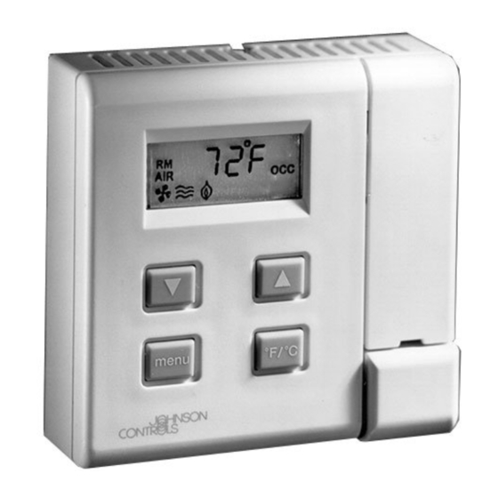
AP-TMZ1600 Room Sensor with LCD Display
Application
The TMZ is compatible with Unitary (UNT) controller
and Variable Air Volume (VAV) (Revision D or later)
controller and with the VAV for Modular Assembly
(VMA1400 Rev. C00 or later and all VMA1200s). Use
HVAC PRO Release 8.01 or later to configure the
UNT, VAV, and VMA for use with the TMZ. See the
Technical Data section for details.
The TMZ connects to the controller via an 8-pin phone
jack cable assembly that provides Zone Bus, sensor,
and power supply connections.
When the TMZ is used with a compatible
Johnson Controls® digital controller, verify proper
system operation using a Zone Terminal Unit (ZTU), a
laptop computer with CBLPRO and HVAC PRO
software, or a Palm compatible handheld interface
with VMA Balancing Tool (VBT) software.
Both the ZTU and CBLPRO plug into the 6-pin phone
jack on the bottom of the TMZ to access the Zone bus.
80 mm
(3.2 in.)
RM
AIR
80 mm
(3.2 in.)
Figure 1: AP-TMZ1600
© 2016 Johnson Controls, Inc.
Part No. 24-8910-7, Rev. G
Code No. LIT-6363110
Segmented
Display
OCC
Light-Emitting
Diode
(LED)
Temporary
Occupancy
Button
inst
24- 8910- 7, Rev . G
Installation Instructions
Installation
Install the TMZ in an accessible location where the
temperature is representative of general room
conditions. Avoid mounting the TMZ near cold or warm
air drafts, radiant heat, or direct sunlight.
IMPORTANT:
Prevent any static electric
discharge to the TMZ1600 Room Sensor. Static
electric discharge can damage the room sensor and
void any warranties.
Note:
Do not mount the module on an exterior wall.
Parts Included
The following parts are included with the TMZ:
•
AP-TMZ1600 Room Sensor with Liquid Crystal
Display (LCD)
•
surface base
•
wallbox mount base (wallplate) with cover screw
(for vertical or horizontal 2 x 4 in. wallbox
mounting)
•
endcaps (2)
•
hollow plastic wall anchors (2)
•
No. 8 x 1-1/4 in. slotted pan-head sheet metal
screws (2), for surface base
•
No. 6-32 x 1/2 in. flat-head machine screws (2), for
wallplate
Special Tools Needed
For a typical installation, you need the following:
•
1.5 mm (1/16 in.) Allen wrench or stat adjustment
tool
•
1/4 in. flat-blade screwdriver
•
8 mm (5/16 in.) drill bit and drill
Issue Date
March 2016
www.johnsoncontrols.com
1
Advertisement

Subscribe to Our Youtube Channel
Related Manuals for Johnson Controls AP-TMZ1600


Summary of Contents for Johnson Controls AP-TMZ1600
- Page 1 24- 8910- 7, Rev . G Installation Instructions Issue Date March 2016 AP-TMZ1600 Room Sensor with LCD Display Application Installation The TMZ is compatible with Unitary (UNT) controller Install the TMZ in an accessible location where the and Variable Air Volume (VAV) (Revision D or later)
- Page 2 3. Drill two 8 mm (5/16 in.) holes at the locations you marked. Note: An ACC-INSL-1 surface mounting pad may be used between the mounting base and the dry wall to accommodate uneven mounting surfaces or block wall drafts. AP-TMZ1600 Room Sensor with LCD Display Installation Instructions...
- Page 3 5. Attach the TMZ to the wallplate, and replace and tighten the cover screw with a 1.5 mm (1/16 in.) Allen wrench or stat adjustment tool. 6. Install the endcaps provided by snapping them onto the wallplate. AP-TMZ1600 Room Sensor with LCD Display Installation Instructions...
- Page 4 Figure 6: Cable and Phone Jack Pinouts connecteur autre qu'un connecteur RJ-45 à 8 broches dans la fiche à 8 broches située à l'arrière de l'TMZ afin d'éviter d'endommager la fiche téléphonique. AP-TMZ1600 Room Sensor with LCD Display Installation Instructions...
-
Page 5: Operation
The TMZ repeats this sequence T MP until the default display (RM AIR) appears. UN - Table 3 describes the LCD display symbols. S By Figure 7: LCD Display Symbols AP-TMZ1600 Room Sensor with LCD Display Installation Instructions... - Page 6 Password Mode: indicates Password mode is active. Error: indicates an error is detected. The specific error is identified by an accompanying number (0 through 6). Refer to Table 5 for specific error message descriptions. AP-TMZ1600 Room Sensor with LCD Display Installation Instructions...
- Page 7 Menu button until the comfort setpoint on the fan operation display to show the fan status. temperature appears (Figure 9). The fan does not display Auto, but does operate in automatic mode. AP-TMZ1600 Room Sensor with LCD Display Installation Instructions...
- Page 8 UnLK after a controller download. 4. Press the arrow buttons to toggle between UnLK and LOCK. UnLK allows a user to control the fan; LOCK prevents a user from controlling the fan. AP-TMZ1600 Room Sensor with LCD Display Installation Instructions...
- Page 9 When the TMZ is used with a VMA1400 and Note: If the controller is configured for a single experiences a power failure, all set values are not setpoint, this screen is skipped. affected except the comfort setpoint temperature access AP-TMZ1600 Room Sensor with LCD Display Installation Instructions...
- Page 10 TMZ Firmware Revision A08 or later is required along with HVAC PRO Release 8.04 or later. Continued on next page . . . AP-TMZ1600 Room Sensor with LCD Display Installation Instructions...
- Page 11 If error persists, replace the controller. Error 1: indicates a RAM Power down the TMZ, then power up again. If the error persists, replace error has been detected. the TMZ. Continued on next page . . . AP-TMZ1600 Room Sensor with LCD Display Installation Instructions...
- Page 12 ** These parts are available from Southwest Wire (SW) or Windy City Wire (WC). Use the appropriate SW or WC suffix to order these parts through the Johnson Controls Preferred Supplier Program. AP-TMZ1600 Room Sensor with LCD Display Installation Instructions...
-
Page 13: Technical Data
The performance specifications are nominal and conform to acceptable industry standards. For application at conditions beyond these specifications, consult the local Johnson Controls office. Johnson Controls, Inc. shall not be liable for damages resulting from misapplication or misuse of its products. - Page 14 507 E. Michigan Street, Milwaukee, WI 53202 Metasys® and Johnson Controls® are registered trademarks of Johnson Controls, Inc. All other marks herein are the marks of their respective owners. © 2016 Johnson Controls, Inc. AP-TMZ1600 Room Sensor with LCD Display Installation Instructions...
Need help?
Do you have a question about the AP-TMZ1600 and is the answer not in the manual?
Questions and answers