Table of Contents
Advertisement
Quick Links
Advertisement
Table of Contents

Related Manuals for Honeywell FS19X Series


Summary of Contents for Honeywell FS19X Series
- Page 1 Installation Guide and Operating Manual ™ Fire and Flame Detectors Model FS19X™ & FS20X™ Series FS19X & FS20X WideBand IR™ / UV Multi-Spectrum Infrared / Ultraviolet Electro-Optical Multi-Spectral Digital WideBand IR Sensor with Ultraviolet Phototube Radiant Energy Fire and Flame Detector...
- Page 2 This manual is subject to change without notice. Copyright 2014 by Honeywell International Inc. While this information is presented in good faith and believed to be accurate, Honeywell disclaims the implied warranties of merchantability and fitness for a particular purpose and makes no express warranties except as may be stated in its written agreement with and for its customers.
-
Page 3: Table Of Contents
4.6.1 Flame Response Sensitivity ......................18 4.6.2 High Temperature Response ......................18 4.6.3 False Alarm Immunity ........................19 4.7 Drawings ..............................20 4.7.1 Outline and Dimensions ........................20 4.7.2 Wiring and Terminal Connections..................... 21 4.7.3 Detector Label Drawings ........................23 INDEX ................................... 25 Honeywell... -
Page 4: Section 1: Introduction
Selecting a unique digital address (128 choices). • Enabling “Fireball” type fire response • Factory Use 3. The ten (10) position Rotary switch allows selection of Figure 1-2 the analog and digital communication protocol. FS19X/FS20X Detector Puck, ( rear view Honeywell... -
Page 5: Detector Technical Specifications
Heater circuit turns ON only when temperature drops below zero degrees Fahrenheit (-17° C) See Section 4.6 for Additional Performance Specifications The supply connection wiring shall be rated at least 10°C above the rated service temperature (120°C for T4 applications and 85°C for T5 applications) Honeywell... -
Page 6: Features & Benefits
• FSC Windows® based PC Interface User can perform remote FS20X Detector diagnostics, real-time status, Real-Time Graphing (RTG), SnapShot data recording, and downloading FirePic’s with Honeywell Analytics’ exclusive FSIM-2 ® USB Interface Unit and easy to use Windows based PC Software. -
Page 7: Applications
Commercial and Military Aircraft Hangars Engine Test Cells Marine Engine Rooms Marine Terminals Paint and Solvent Storage Power Plants Product Storage Terminals Rail and Truck Loading and Unloading Terminals Silane Gas Cabinets Silane Gas Manufacturing Hydrogen Plants Hydrogen Storage General Warehouses Honeywell... -
Page 8: Section 2: Installation
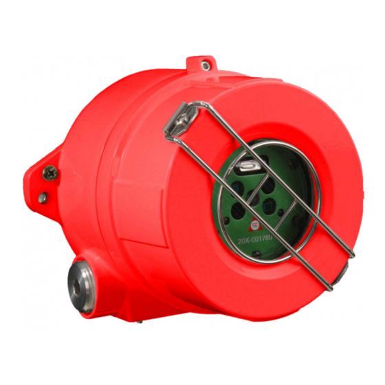
¾ in. NPT or 25mm (see Figure 2-2). b) Install an approved conduit trap or drain, if required to meet hazardous area classifications per NFPA 70: National Electrical Code, latest revision. Figure 2-1 Detector (front view) Swivel Mount Figure 2-2 Figure 2-3 Mounting Instructions (continued) Honeywell... -
Page 9: Opening The Detector
CAUTION: Disconnect power before unscrewing the Housing Lid. 4. Loosen the set screw on the enclosure lid (see Figure 2-5). Figure 2-5 5. Turn counterclockwise (CCW) to unscrew the enclosure lid (see Figure 2-6). Figure 2-6 Opening the Detector (continued) Honeywell... - Page 10 Alarm COM 4-20mA Sink Fault NO Fault COM Figure 2-9 +24 VDC Detector Module “puck” (rear view) DC Return Contacts shown with no power applied Note: Do not attempt to open the Detector Module “puck” as this voids all warranties. Honeywell...
-
Page 11: Detector Connections
3. The FSX Detector is securely mounted and has an unobstructed view of the area of coverage (Section 2.1). 4. The Detector window is unobstructed and clean. The Detector is now ready for Power-Up. On Power-Up, the Fault Relay will change status if the Factory Default Setting is used (Section 3.2). Honeywell... -
Page 12: Start-Up And Commissioning
Detector test “end to end”. Using an external hand-held test lamp ensures that the Detector has a clear unobstructed view of the threat area. Note: Honeywell Analytics FSX Detectors feature an automatic built-in "through the lens" test that verifies the cleanliness of its viewing window lens every three seconds and tests it internal electronics and software. - Page 13 Remember to disable the outputs, as a full functional test includes activating the ALARM outputs. A Honeywell Analytics Test Lamp must be used for this test (Section 4.4). Point the Test Lamp directly at the front of the Detector (on axis as much as possible, within a distance of about 1 to 25 feet). Activate the Test Lamp by pressing and holding its pushbutton.
-
Page 14: Section 3: Operation
Built-in microprocessors use sophisticated Digital Signal Processing (DSP) to accurately distinguish radiant energy from a real fire and a false alarm source(s). Honeywell Analytics has developed and refined these complex proprietary and patented WideBand IR and UV algorithms for over a quarter of a century since 1981. - Page 15 Factory Use Only default setting. Use Table on the right Factory Use Only and Figure 3-3 to configure SW3. Factory Use Only Figure 3-3 SW3 Factory Use Only Ten (10) Position Rotary Switch Factory Use Only Honeywell...
-
Page 16: Normal Operation
• 4-20 mA (source 20 mA) Auxiliary Output • RS-485 FireBus Alarm Notification • RS-485 ModBus Alarm Notification 1 This output is a Verified Alarm Output Figure 3-5 2 Only one active Alarm output from this group Red LED Location Honeywell... -
Page 17: Maintenance
Additionally, semi-annual or quarterly testing should be performed, using the correct Honeywell Analytics Test Lamp, to ensure the integrity of the entire fire protection system. The optical window (lens) of the Model FS19X/FS20X Detector should be clean in order to ensure the Detector is operating properly at all times. -
Page 18: Section 4: Appendix
Honeywell Analytics warrants its Products against defects in material and workmanship under normal use and service for a period of three (3) years from the date of shipment as described herein. Honeywell Analytics, at its option, will repair or replace, at no charge, such products found to be defective during the warranty period provided that they are returned in accordance with the terms of this warranty. -
Page 19: Product Variations
2 = High Temperature Applications 3 = Fast Response (0.5 Seconds) Manufacturer’s Code 2 = Standard Honeywell Analytics Detector – Full Window FS19X-211-213 MultiBand IR plus UV Detector, General Applications with Relays, 4-20mA Output, FireBus Aluminum Enclosure with ¾ inch NPT Conduit Entries, Class... -
Page 20: Digital Communication Options
Some manufacturers claim that their detectors do not need remote testing with an external Test Lamp because it tests itself. Even though Honeywell Analytics Detectors also perform “through the lens” self-testing and tests themselves, Honeywell Analytics, in compliance with NFPA 72 codes, has developed portable test lamps for periodical “end-to-end”... -
Page 21: Additional Performance Specifications
< 3 Seconds 4.6.2 High Temperature Response The optional extended temperature range FS19X/FS20X Detector will respond to a one (1) square foot n-heptane reference fire at a distance of 35 feet in 2 to 5 seconds, when the temperature exceeds 85°C. Honeywell... -
Page 22: 4.6.3 False Alarm Immunity
Source at 3 feet / 91.44 centimeters Pelican Flashlight 1 foot / 30.48 centimeters Fire at 200 feet / 60.96 meters Source at 3 feet / 91.44 centimeters Incandescent Lamp 1 foot / 30.48 centimeters Fire at 200 feet / 60.96 meters Honeywell... -
Page 23: Drawings
Installation Guide and Operating Manual // Model FS19X™ & FS20X™ Series Drawings 4.7.1 Outline and Dimensions Figure 4-3 Outline & Dimesional Drawing for FS19X/FS20X Figure 4-4 Outline & Dimesional Drawing for SM4 Honeywell... -
Page 24: Wiring And Terminal Connections
1. Cable shield must be grounded at one end only, at the Control Panel. Coil and tape cable shield at the Detector end. 2. Set SW3 (rotary switch) to position one (1) for Source current wiring. 3. Set SW3 (rotary switch) to position zero (0) for Sink current wiring. Honeywell... - Page 25 3. Fault relay contacts shown with no power applied. During normal operation and with no Fault, this relay will De-Energize and the N.O. (normally open) contacts will close. 4. EOL (End-Of-Line) device shall be installed as required and supplied by the Fire Alarm Panel. Honeywell...
-
Page 26: Detector Label Drawings
-40C to +110C Stainless Steel +75C +60C LB-6093- -40C to -40C to FS20X 0.020' Al 1100-Hl4 Black White -40C to +110C +75C +60C LB-6093- 0.020' 316 -40C to -40C to FS20X Polished Black -40C to +110C Stainless Steel +75C +60C Honeywell... -
Page 27: Index
FireBus I, 13, 15 FireBus II, 13, 14 Temperature, 4, 15 Test Lamp, 11, 15, 18 Trouble, 15 Green LED, 14 Warranty Information, 16 weather-proof, 9 Hazardous Locations, 2 Yellow LED, 14, 15 Installation Practices, 9, 11 LED Status Indicators, 14 Honeywell... - Page 28 Honeywell Analytics Asia Pacific Co., Ltd. #701 Kolon Science Valley (1) 43 Digital-Ro 34-Gil, Guro-Gu Seoul, 152-729 Korea Email: analytics.ap@honeywell.com Internet These Honeywell websites may be of interest to Industry Solution customers. Honeywell Organization Corporate www.honeywell.com Honeywell Analytics www.honeywellanalytics.com Telephone Contact us by telephone at these numbers.
- Page 29 Installation Guide and Operating Manual // Model FS19X™ & FS20X™ Series 1998M0902 Rev. A July, 2014 © 2014 Honeywell International Inc.
Need help?
Do you have a question about the FS19X Series and is the answer not in the manual?
Questions and answers