
Subscribe to Our Youtube Channel
Related Manuals for Ross CMA-8011A


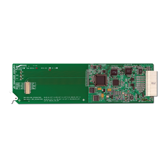
Summary of Contents for Ross CMA-8011A
- Page 1 Ross Video Limited CMA-8011A Component Monitoring Amplifier User Manual Ross Part Number: 8011ADR-004 Issue: 05...
- Page 2 The information contained in this User Manual is subject to change without notice or obligation. Copyright © 2005 Ross Video Limited. All rights reserved. Contents of this publication may not be reproduced in any form without the written permission of Ross Video Limited. Reproduction or reverse engineering of copyrighted software is prohibited. Notice The material in this manual is furnished for informational use only.
- Page 3 Important Regulatory and Safety Notices Before using this product and any associated equipment, refer to the “Important Safety Instructions” listed below so as to avoid personnel injury and to prevent product damage. Products may require specific equipment, and /or installation procedures be carried out to satisfy certain regulatory compliance requirements.
- Page 4 Operation of this equipment in a residential area is likely to cause harmful interference in which case users will be required to correct the interference at their own expense. Changes or modifications to this equipment not expressly approved by Ross Video Ltd. could void the user’s authority to operate this equipment.
- Page 5 The crossed-out wheeled bin symbol invites you to use these systems. If you need more information on the collection, reuse, and recycling systems, please contact your local or regional waste administration. You can also contact Ross Video for more information on the environmental performances of our products.
-
Page 7: Table Of Contents
In This Chapter ........................4-1 CMA-8011A Technical Specifications ..............4-2 Service Information In This Chapter ........................5-1 Troubleshooting Checklist ..................5-1 Warranty and Repair Policy ..................5-2 Ordering Information In This Chapter ........................6-1 CMA-8011A Component Monitoring Amp and Related Products ......6-1 Contents • i CMA-8011A User Manual (Iss.05) - Page 8 • Contents CMA-8011A User Manual (Iss.05)
-
Page 9: Introduction
Congratulations on choosing the Ross Video CMA-8011A Component Monitoring Amplifier. The CMA-8011A is part of a full line of digital products within the RossGear Terminal Equipment family of analog and digital products, backed by Ross Video’s experience in engineering and design expertise since 1974. -
Page 10: Overview
Of special interest on the CMA-8011A is the inclusion of an adjustable analog cable equalizer for the analog output signal. This adjustment can be set to equalize up to 90 meters (300 ft.) of Belden 8281 cable, thus ensuring that the monitoring signal is delivered to the destination without chroma loss. -
Page 11: Features
Features The following features make the CMA-8011A one of the finest Component Monitoring Amplifiers on the market today: • Input and conversion status indicator LED's • Input level/strength detection • Auto-reclocking of serial digital input • Input equalization for up to 305 meters (1000 ft.) of cable •... - Page 12 1-4 • Introduction CMA-8011A User Manual (Iss.05)
-
Page 13: Installation And Setup
Unpacking Unpack each CMA-8011A card you received from the shipping container, and check the contents against the packing list to ensure that all items are included. If any items are missing or damaged, contact your sales representative or Ross Video directly. -
Page 14: Analog Output Setup Switches
For NTSC - North America SETUP For all other systems NORMAL Normal operation MODE Produces an analog color bar output. BARS (Requires a valid 270Mb/s input signal.) 6 - 8 Reserved for future use. 2-2 • Installation and Setup CMA-8011A User Manual (Iss.05) -
Page 15: Output Mute Jumper
See Chapter 3, “SMPTE 269M Fault Reporting” for complete details. Equalization Setting Use figure 2, the card labeling, and the following discussion to adjust the CMA-8011A equalization setting. Set the analog output EQUALIZATION adjustment (RV2) for the cable length used between the amplifier and analog destination equipment. -
Page 16: Cable Connections
Cable Connections The following diagram indicates the input and output connections for coax cables to the CMA-8011A when mounted in RossGear 8000 series digital frames. Input Out 2 Out 1 Out 4 Out 3 Composite Out 2 Composite Out 1... - Page 17 The monitoring amp is on "TEST" mode or the input Red short flash signal is not a 4:2:2, 270Mb/s signal (i.e. input signal is 10% duty cycle 143Mb/s 4Fsc). Installation and Setup • 2-5 CMA-8011A User Manual (Iss.05)
- Page 18 2-6 • Installation and Setup CMA-8011A User Manual (Iss.05)
-
Page 19: Smpte 269M Fault Reporting
The SMPTE 269M Fault Reporting system, also known as a SMPTE “alarm”, provides indication if one or more frame modules encounter a fault or an abnormal condition. The CMA-8011A module provides a jumper to enable SMPTE-269M fault reporting. The card connects by means of an internal interface circuit to an auxiliary telco connector on RossGear 8000 series frames. -
Page 20: Jumper Setup
Jumper Setup If fault reporting for the CMA-8011A is desired, use jumper JP5 - FAULT REPORT (269M) to set up the card. 1. To access the jumper, remove the card from the frame by pressing down the white card ejector tab and pulling the card from the frame slot. -
Page 21: Specifications
Specifications In This Chapter This chapter contains the CMA-8011A Technical Specifications table. Specifications • 4-1 CMA-8011A User Manual (Iss.05) -
Page 22: Cma-8011A Technical Specifications
± 10ns to 5.5MHz RMS Noise (unweighted) -52dB 0 - 5.0MHz Equalization 0 - 300 Feet +/-0.5dB Positive Rail 475mA Power Negative Rail 10mA Consumption Total Power Draw 3.3W Specifications are subject to change without notification. 4-2 • Specifications CMA-8011A User Manual (Iss.05) -
Page 23: Service Information
Routine maintenance to this RossGear product is not required. In the event of problems with your CMA-8011A, the following basic troubleshooting checklist may help identify the source of the problem. If the module still does not appear to be working properly after checking all possible causes, please contact your Ross Video products distributor, or the Ross Video Technical Support department at the numbers listed under the “Contact Us”... -
Page 24: Warranty And Repair Policy
FIVE (5) years from the date of shipment from our factory. In the event that your RossGear CMA-8011A proves to be defective in any way during this warranty period, Ross Video Limited reserves the right to repair or replace this piece of equipment with a unit of equal or superior performance characteristics. -
Page 25: Ordering Information
Power Supply (PS-8102) (2RU, holds 10 modules, includes 1 power supply) Your CMA-8011A Component Monitoring Amplifier is part of the RossGear family of products. Ross Video offers a full line of RossGEAR terminal equipment including distribution, conversion, monitoring, synchronizers, encoders, decoders, keyers, switchers, as well as analog audio and video products. - Page 26 Notes: 6-2 • Ordering Information CMA-8011A User Manual (Iss. 01)
- Page 27 Notes: Ordering Information • 6-3 CMA-8011A User Manual (Iss.05)
- Page 28 613 • 652 • 4886 ext. 333 After-hours Emergency 613 • 652 • 4425 General Information solutions@rossvideo.com E-MAIL Technical Support techsupport@rossvideo.com 8 John Street, Ross Video Limited Iroquois, Ontario, Canada POSTAL K0E 1K0 SERVICE P.O. Box 880, Ross Video Incorporated Ogdensburg, New York, USA 13669- 0880...
Need help?
Do you have a question about the CMA-8011A and is the answer not in the manual?
Questions and answers