HP Compaq 2710p Maintenance And Service Manual
Hp compaq 2710p: user guide
Hide thumbs
Also See for Compaq 2710p:
- Maintenance and service manual (139 pages) ,
- Getting started (58 pages) ,
- User manual (26 pages)
Table of Contents
Advertisement
Quick Links
Advertisement
Table of Contents

Related Manuals for HP Compaq 2710p


Summary of Contents for HP Compaq 2710p
- Page 1 HP Compaq 2710p Notebook PC Maintenance and Service Guide...
- Page 2 The information contained herein is subject to change without notice. The only warranties for HP products and services are set forth in the express warranty statements accompanying such products and services. Nothing herein should be construed as constituting an additional warranty.
- Page 3 Safety warning notice WARNING! To reduce the possibility of heat-related injuries or of overheating the computer, do not place the computer directly on your lap or obstruct the computer air vents. Use the computer only on a hard, flat surface. Do not allow another hard surface, such as an adjoining optional printer, or a soft surface, such as pillows or rugs or clothing, to block airflow.
- Page 4 Safety warning notice...
-
Page 5: Table Of Contents
Table of contents 1 Product description 2 External component identification Top components ... 6 Display components ... 6 Buttons, switches, and pointing devices ... 7 Lights ... 8 Keys ... 10 Front components ... 11 Rear components ... 12 Right-side components ... 13 Left-side components ... - Page 6 SIM ... 38 Hard drive ... 39 WLAN module ... 41 WWAN module ... 45 Memory module ... 47 Keyboard ... 48 Hinge cover ... 50 Top cover ... 52 RTC battery ... 55 Audio connector board ... 56 Bluetooth module ... 57 Speaker ...
- Page 7 8 Backup and recovery in Windows Vista Creating recovery discs ... 98 Backing up your information ... 99 When to back up ... 99 Backup suggestions ... 99 Backing up specific files or folders ... 100 Backing up the entire hard drive ... 100 Creating recovery points ...
- Page 8 viii...
-
Page 9: Product Description
Product description Category Description Branding HP Compaq 2710p Notebook PC Processors Intel® Core™ Duo Ultra-Low-Voltage (ULV) processors: ● ● Chipsets ● ● Graphics Intel Graphics Media Accelerator DX10, supports 64-bit memory bus Panels ● ● ● ● ● ● Memory ●... - Page 10 ● Optical drives Optical drives supported only through the HP 3-in-1 NAS Docking Station, HP Advanced Docking Station, HP Docking Station, and HP External USB 2.0 MultiBay II Cradle (all required software is preinstalled on the computer) Diskette drive ●...
- Page 11 ● Windows Vista® hardware Start button ● Durable key caps ● Power Primary batteries: requirements 6-cell, 44-Wh, Li-ion battery with fuel gauge ● Supports the HP 2700 Ultra-Slim Battery (which can also be used while the computer is docked) ●...
- Page 12 Category Description 65-watt Smart AC adapter with localized cable plug support and 3-wire plug Security ● ● ● ● Operating system Preinstalled: ● ● ● ● ● ● Restore media: ● ● ● ● ● Preinstalled with Office: ● ● ●...
- Page 13 Category Description ● Wireless modules ●...
-
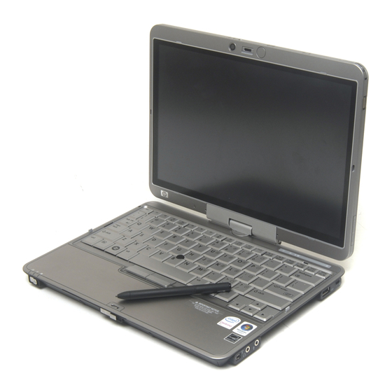
Page 14: External Component Identification
Integrated camera (select models only) Camera light (select models only) Camera mode switch Keyboard light Keyboard light button HP Fingerprint Sensor (fingerprint reader) Chapter 2 External component identification Description Records video, captures still photographs, and transmits streaming video for video conferencing. -
Page 15: Buttons, Switches, And Pointing Devices
Item Component Internal microphones (2) Convertible hinge Ambient light sensor Buttons, switches, and pointing devices Item Component Internal display switch Pointing stick* Presentation button Volume mute button Volume scroll zone Left pointing stick button* Description Record sound and transmit sound for video conferencing. Swivels the display and converts the computer from traditional notebook mode into tablet mode or vice versa. -
Page 16: Lights
Item Component Right pointing stick button* *This table describes factory settings. View or change pointing device preferences as follows: In Windows Vista, select Start > Control Panel > Hardware and Sound > Mouse. ● In Windows XP, select Start > Control Panel > Printers and Other Hardware > Mouse. ●... - Page 17 Volume down light Volume up light Num lock light Function Blinking green: The hard drive is being accessed. ● Amber: HP 3D DriveGuard has temporarily parked the ● internal hard drive. On: Caps lock is on. Off: Computer sound is on. ●...
-
Page 18: Keys
Keys Item Component Windows logo key Windows applications key Embedded numeric keypad keys Function keys Chapter 2 External component identification Description Displays system information when pressed in combination with the key. Executes frequently used system functions when pressed in combination with a function key or the Displays the Windows Start menu. -
Page 19: Front Components
Front components Item Component Camera light (select models only) Camera mode switch Keyboard light button External WWAN antenna button External WWAN antenna Power switch Display release latch Bluetooth® compartment Function On: The camera is recording or streaming video or capturing a still photograph. To use macro mode, slide the switch to the left. -
Page 20: Rear Components
Rear components Item Component Rotate button Windows security button* RJ-11 (modem) jack RJ-45 (network) jack External monitor port Power connector *To protect your work and the system, the ctrl+alt+delete command cannot be entered using the ctrl, alt, and screen keyboard. Chapter 2 External component identification Function Rotates the screen image clockwise into 4 orientations:... -
Page 21: Right-Side Components
Right-side components Item Component HP Fingerprint Sensor (fingerprint reader) 1394 port Audio-out (headphone) jack Audio-in (microphone) jack Media Card Reader USB port Security cable slot Function Allows a fingerprint logon to Windows instead of a password logon. Connects an optional IEEE 1394 or 1394a device, such as a camcorder. -
Page 22: Left-Side Components
Supports optional ExpressCards. Supports smart cards and Java™ cards. ● Blue: An integrated wireless device, such as a wireless local area network (WLAN) device, the HP Broadband Wireless Module, and/or a Bluetooth device, is on. Amber: All wireless devices are off. ●... -
Page 23: Bottom Components
Bottom components Item Component Battery bay Speaker SIM slot Vents (3) Hard drive compartment Docking connector Charge level indicator Battery release latch Accessory battery connector (10) Accessory battery connector door Function Holds the battery. Produces sound. Contains a SIM. The SIM slot is located inside the battery bay. -
Page 24: Illustrated Parts Catalog
Illustrated parts catalog Serial number location When ordering parts or requesting information, provide the computer serial number and model number located on the bottom of the computer. Chapter 3 Illustrated parts catalog... -
Page 25: Computer Major Components
Computer major components Item Description 12.1-inch, WXGA, WVA display assemblies (include ambient light sensor, fingerprint reader, microphones, WLAN antenna cables, and WWAN antenna cables) Display assembly with camera and keyboard light Spare part number 454679-001 Computer major components... - Page 26 Item Description Display assembly with camera Display assembly with keyboard light Display assembly Display internal components (not illustrated): Fingerprint reader board Microphones (includes 2 receivers and cables) External WWAN antenna Keyboards (include pointing stick and pointing stick cable) Belgium Brazil The Czech Republic Denmark France...
- Page 27 Item Description Thailand Turkey The United Kingdom The United States Plastics Kit (see Plastics Kit on page 23 (3a) Hinge cover (3b) ExpressCard slot bezel (3c) Hard drive compartment cover (includes 6 captive screws, secured by C-clips) Bluetooth module cover (not illustrated) Top cover (includes LED board and cable and display alignment guides) RTC battery (includes double-sided tape) Audio connector board (includes cable)
- Page 28 Item Description Denmark, Djibouti, Dominica, the Dominican Republic, East Timor, Ecuador, Egypt, El Salvador, Equitorial Guinea, Eritrea, Estonia, Ethiopia, Fiji, Finland, France, French Guiana, Gabon, Gambia Georgia, Germany, Ghana, Gibraltar, Greece, Grenada, Guadeloupe, Guam, Guatemala, Guinea, Guinea-Bissa, Guyana, Haiti, Honduras, Hong Kong, Hungary, Iceland, India, Ireland, Italy, the Ivory Coast, Jamaica, Jordan, Kenya, Kiribati, Kyrgyzstan, Laos, Latvia, Lesotho, Liberia, Liechtenstein, Lithuania, Luxembourg, Macedonia, Madagascar, Malawi, the Maldives, Mali, Malta, the Marshall Islands,...
- Page 29 Item Description Maldives, Mali, Malta, the Marshall Islands, Martinique, Mauritania, Mauritius, Mexico, Micronesia, Monaco, Mongolia, Montenegro, Morocco, Mozambique, Namibia, Nauru, Nepal, the Nether Antilles, the Netherlands, New Zealand, Nicaragua, Niger, Nigeria, Norway, Oman, Pakistan, Palau, Panama, Papua New Guinea, Paraguay, Peru, the Philippines, Poland, Portugal, the Republic of Moldova, Romania, Russia, Rwanda, Samoa, San Marino, Sao Tome &...
- Page 30 Item Description Kitts & Nevis, St. Lucia, St. Vincent & Grenada, Suriname, Swaziland, Sweden, Switzerland, Taiwan, Tajikistan, Tanzania, Thailand, Togo, Tonga, Trinidad & Tobago, Tunisia, Turkey, Turkmenistan, Tuvalu, Uganda, Ukraine, the United Arab Emirates, the United Kingdom, Uruguay, Uzbekistan, Vanuatu, Venezuela, Vietnam, Yemen, Zaire, Zambia, and Zimbabwe ●...
-
Page 31: Plastics Kit
Hard drive compartment cover (includes 6 captive screws, secured by C-clips) Bluetooth module cover Miscellaneous parts Description 65-watt AC adapter (HP Smart AC Adapter) External MultiBay II External MultiBay II power cable and stand HP 2700 Ultra-Slim Expansion Base Label Kit... - Page 32 Description For use in Denmark For use in Europe, the Middle East, and Africa For use in India For use in Israel For use in Italy For use in Japan For use in the People's Republic of China For use in South Africa For use in South Korea For use in Switzerland For use in Thailand...
-
Page 33: Sequential Part Number Listing
409497-291 Intel 802.11a/b/g WLAN module for use in Japan 417220-001 65-watt AC adapter (HP Smart AC Adapter) 436255-001 Broadcom 802.11a/b/g/n WLAN module for use in Canada, the Cayman Islands, Guam, Puerto Rico, the U.S. Virgin Islands, and the United States 436255-291 Broadcom 802.11a/b/g/n WLAN module for use in Japan... - Page 34 Spare part Description number Germany, Ghana, Gibraltar, Greece, Grenada, Guadeloupe, Guam, Guatemala, Guinea, Guinea-Bissa, Guyana, Haiti, Honduras, Hong Kong, Hungary, Iceland, India, Ireland, Italy, the Ivory Coast, Jamaica, Jordan, Kenya, Kiribati, Kyrgyzstan, Laos, Latvia, Lesotho, Liberia, Liechtenstein, Lithuania, Luxembourg, Macedonia, Madagascar, Malawi, the Maldives, Mali, Malta, the Marshall Islands, Martinique, Mauritania, Mauritius, Mexico, Micronesia, Monaco, Mongolia, Montenegro, Morocco, Mozambique, Namibia, Nauru, Nepal, the Netherlands, New Zealand, Nicaragua, Niger, Nigeria, Norway, Oman, Pakistan, Palau, Panama, Papua...
- Page 35 Spare part Description number 441086-002 Intel 802.11a/b/g/n WLAN module for use in Austria, Azerbaijan, Bahrain, Belgium, Brazil, Bulgaria, Croatia, Cyprus, the Czech Republic, Denmark, Egypt, Estonia, Finland, France, Georgia, Germany, Greece, Hungary, Iceland, Ireland, Israel, Italy, Latvia, Lebanon, Liechtenstein, Lithuania, Luxembourg, Malta, Monaco, the Netherlands, Norway, Oman, the Philippines, Poland, Portugal, Qatar, Romania, Russia, Serbia and Montenegro, Singapore, Slovakia, Slovenia, South Africa, Spain, Sri Lanka, Sweden, Switzerland, Turkey, Ukraine, the United Kingdom, and Uzbekistan...
- Page 36 Spare part Description number 454672-001 1024-MB memory module (PC2-5300, 667-MHz, DDR2) 454673-001 2048-MB memory module (PC2-5300, 667-MHz, DDR2) 454674-001 512-MB memory module (PC2-5300, 667-MHz, DDR2) 454675-001 12.1-inch, WXGA, WVA display assembly with camera module (includes ambient light sensor, fingerprint reader, microphones, WLAN antenna cables, and WWAN antenna cables) 454676-001 12.1-inch, WXGA, WVA display assembly (includes ambient light sensor, fingerprint reader, microphones, WLAN antenna cables, and WWAN antenna cables)
- Page 37 System board equipped with Intel Core 2 Duo U7500 1.06-MHz processor (includes replacement thermal material) 455083-001 System board equipped with Intel Core 2 Duo U7600 1.20-MHz processor (includes replacement thermal material) 455953-001 HP 2700 Ultra-Slim Expansion Base Sequential part number listing...
-
Page 38: Removal And Replacement Procedures
Removal and replacement procedures Preliminary replacement requirements Tools required You will need the following tools to complete the removal and replacement procedures: Flat-bladed screwdriver ● Magnetic screwdriver ● Phillips P0 and P1 screwdrivers ● Torx T8 screwdriver ● Service considerations The following sections include some of the considerations that you must keep in mind during disassembly and assembly procedures. -
Page 39: Cables And Connectors
Cables and connectors CAUTION: When servicing the computer, be sure that cables are placed in their proper locations during the reassembly process. Improper cable placement can damage the computer. Cables must be handled with extreme care to avoid damage. Apply only the tension required to unseat or seat the cables during removal and insertion. -
Page 40: Grounding Guidelines
Grounding guidelines Electrostatic discharge damage Electronic components are sensitive to electrostatic discharge (ESD). Circuitry design and structure determine the degree of sensitivity. Networks built into many integrated circuits provide some protection, but in many cases, ESD contains enough power to alter device parameters or melt silicon junctions. A discharge of static electricity from a finger or other conductor can destroy static-sensitive devices or microcircuitry. -
Page 41: Packaging And Transporting Guidelines
Packaging and transporting guidelines Follow these grounding guidelines when packaging and transporting equipment: To avoid hand contact, transport products in static-safe tubes, bags, or boxes. ● Protect ESD-sensitive parts and assemblies with conductive or approved containers or packaging. ● Keep ESD-sensitive parts in their containers until the parts arrive at static-free workstations. ●... -
Page 42: Equipment Guidelines
Equipment guidelines Grounding equipment must include either a wrist strap or a foot strap at a grounded workstation. When seated, wear a wrist strap connected to a grounded system. Wrist straps are flexible straps ● with a minimum of one megohm ±10% resistance in the ground cords. To provide proper ground, wear a strap snugly against the skin at all times. -
Page 43: Unknown User Password
Unknown user password If the computer you are servicing has an unknown user password, follow these steps to clear the password: NOTE: These steps also clear CMOS. Shut down the computer. If you are unsure whether the computer is off or in Hibernation, turn the computer on, and then shut it down through the operating system. -
Page 44: Component Replacement Procedures
Make special note of each screw size and location during removal and replacement. Serial number Report the computer serial number to HP when requesting information or ordering spare parts. The serial number is located on the bottom of the computer. Computer feet The computer feet are adhesive-backed rubber pads. -
Page 45: Battery
Battery Description 6-cell, 4.4-Wh battery Before disassembling the computer, follow these steps: Shut down the computer. If you are unsure whether the computer is off or in Hibernation, turn the computer on, and then shut it down through the operating system. Disconnect all external devices connected to the computer. -
Page 46: Sim
NOTE: This section applies only to computer models with WWAN capability. NOTE: If there is a SIM inserted in the SIM slot, it must be removed before disassembling the computer. Be sure that the SIM is reinserted in the SIM slot after reassembling the computer. Before removing the SIM, follow these steps: Shut down the computer. -
Page 47: Hard Drive
Hard drive NOTE: All hard drive spare part kits include an isolator and connector cable. Description 100-GB, 4200-rpm hard drive 80-GB, 4200-rpm hard drive 60-GB, 4200-rpm hard drive Before removing the hard drive, follow these steps: Shut down the computer. If you are unsure whether the computer is off or in Hibernation, turn the computer on, and then shut it down through the operating system. - Page 48 Remove the hard drive bracket (2). Disconnect the hard drive connector (1) from the system board. Release the hard drive (2) by sliding it to the right. Lift the hard drive (3) straight up to remove it from the hard drive compartment. Reverse this procedure to install the hard drive.
-
Page 49: Wlan Module
WLAN module CAUTION: The WLAN module and the WWAN module are not interchangeable. Description Broadcom 802.11a/b/g/n WLAN modules: For use in Canada, the Cayman Islands, Guam, Puerto Rico, the U.S. Virgin Islands, and the ● United States ● For use in Afghanistan, Albania, Algeria, Andorra, Angola, Antigua & Barbuda, Argentina, Armenia, Aruba, Australia, Austria, Azerbaijan, the Bahamas, Bahrain, Bangladesh, Barbados, Belgium, Belize, Benin, Bermuda, Bolivia, Bosnia &... - Page 50 Description Brazil, the British Virgin Islands, Brunei, Bulgaria, Burkina Faso, Burundi, Cameroon, Cape Verde, the Central African Republic, Chad, Chile, the People's Republic of China, Colombia, Comoros, the Congo, Costa Rica, Croatia, Cyprus, the Czech Republic, Denmark, Djibouti, Dominica, the Dominican Republic, East Timor, Ecuador, Egypt, El Salvador, Equitorial Guinea, Eritrea, Estonia, Ethiopia, Fiji, Finland, France, French Guiana, Gabon, Gambia, Georgia, Germany, Ghana, Gibraltar, Greece, Grenada, Guadeloupe, Guatemala, Guinea, Guinea- Bissa, Guyana, Haiti, Honduras, Hong Kong, Hungary, Iceland, India, Ireland, Israel, Italy, the...
- Page 51 Description Norway, Oman, Palau, Panama, Papua New Guinea, Paraguay, the People's Republic of China, Peru, the Philippines, Poland, Portugal, Qatar, the Republic of Moldova, Romania, Russia, Rwanda, Samoa, San Marino, Sao Tome & Principe, Saudi Arabia, Senegal, Serbia and Montenegro, the Seychelles, Sierra Leone, Singapore, Slovakia, Slovenia, the Solomon Islands, Somalia, South Africa, South Korea, Spain, Sri Lanka, St.
- Page 52 Remove the WLAN module (4) by pulling the module away from the slot at an angle. NOTE: WLAN modules are designed with a notch (5) to prevent incorrect installation. Reverse this procedure to install the WLAN module. Chapter 4 Removal and replacement procedures...
-
Page 53: Wwan Module
WWAN module CAUTION: The WLAN module and the WWAN module are not interchangeable. Description Cingular HSDPA WWAN module Qualcomm EV-DO WWAN module Sprint EV-DO WWAN module Verizon EV-DO WWAN module Vodafone HSDPA WWAN module Before removing the WWAN module, follow these steps: Shut down the computer. - Page 54 Remove the WWAN module (3) by pulling the module away from the slot at an angle. NOTE: WWAN modules are designed with a notch (4) to prevent incorrect installation. Reverse this procedure to install the WWAN module. Chapter 4 Removal and replacement procedures...
-
Page 55: Memory Module
Memory module Description 2048-MB (PC2-5300, 667-MHz, DDR2) 1024-MB (PC2-5300, 667-MHz, DDR2) 512-MB (PC2-5300, 667-MHz, DDR2) Before removing the memory module, follow these steps: Shut down the computer. If you are unsure whether the computer is off or in Hibernation, turn the computer on, and then shut it down through the operating system. -
Page 56: Keyboard
Keyboard For use in: Belgium Brazil The Czech Republic Denmark France French Canada Germany Greece Hungary Iceland Israel Italy Japan Latin America The Netherlands and Europe Before removing the keyboard, follow these steps: Shut down the computer. If you are unsure whether the computer is off or in Hibernation, turn the computer on, and then shut it down through the operating system. - Page 57 Remove the keyboard: Remove the following: (1) One small Mylar screw cover. The screw covers detailed in this section are available in the Rubber Kit, spare part number 454686-001. (2) One medium Mylar screw cover. (3) Six Torx T8M2.0×8.0 screws. Turn the computer display-side up, with the front toward you.
-
Page 58: Hinge Cover
Release the ZIF connector (2) to which the keyboard cable is attached, and disconnect the keyboard cable (3) from the system board. Remove the keyboard. Reverse this procedure to install the keyboard. Hinge cover NOTE: The hinge cover is included in the Plastics Kit, spare part number 454685-001. Before removing the hinge cover, follow these steps: Shut down the computer. - Page 59 Remove the two Torx T8M2.0×5.0 screws that secure the hinge cover to the computer. Turn the computer right-side up, with the rear panel toward you. Open the computer to an upright position. Remove the hinge cover by pulling it away from the computer. Reverse this procedure to install the hinge cover.
-
Page 60: Top Cover
Top cover Description Top cover (includes LED board and cable and display alignment guides) Before removing the top cover, follow these steps: Shut down the computer. If you are unsure whether the computer is off or in Hibernation, turn the computer on, and then shut it down through the operating system. - Page 61 Remove the following: (1) One small Mylar screw cover. All Mylar screw covers detailed in this section are included in the Rubber Kit, spare part number 454686-001. (2) Three Torx T8M2.0×8.0 screws. (3) Two large Mylar screw covers. The screw covers detailed in this section are included in the Rubber Kit, spare part number 454686-001.
- Page 62 Remove the top cover (4) by pulling it away from the computer at an angle. Reverse this procedure to install the top cover. Chapter 4 Removal and replacement procedures...
-
Page 63: Rtc Battery
RTC battery NOTE: Removing the RTC battery and leaving it uninstalled for 5 or more minutes causes all passwords and CMOS settings to be cleared. Description RTC battery (includes double-sided tape) Before removing the RTC battery, follow these steps: Shut down the computer. If you are unsure whether the computer is off or in Hibernation, turn the computer on, and then shut it down through the operating system. -
Page 64: Audio Connector Board
Audio connector board Description Audio connector board (includes cable) Before removing the audio connector board, follow these steps: Shut down the computer. If you are unsure whether the computer is off or in Hibernation, turn the computer on, and then shut it down through the operating system. Disconnect all external devices connected to the computer. -
Page 65: Bluetooth Module
Reverse this procedure to install the audio connector board. Bluetooth module Description Bluetooth (includes cable) Before removing the Bluetooth module, follow these steps: Shut down the computer. If you are unsure whether the computer is off or in Hibernation, turn the computer on, and then shut it down through the operating system. -
Page 66: Speaker
Remove the Bluetooth module and cable (4) from the base enclosure. Reverse this procedure to install the Bluetooth module. Speaker Description Speaker Before removing the speaker, follow these steps: Shut down the computer. If you are unsure whether the computer is off or in Hibernation, turn the computer on, and then shut it down through the operating system. - Page 67 Remove the speaker: Disconnect the speaker cable (1) from the system board. Remove the speaker cable (2) from the clip built into the base enclosure. Remove the Phillips PM2.0×6.0 screw (3) that secures the speaker to the base enclosure. Remove the speaker (4) from the base enclosure. Reverse this procedure to install the speaker.
-
Page 68: Display Assembly
Display assembly NOTE: All display assembly spare part kits include an ambient light sensor, fingerprint reader, microphones, WLAN antenna cables, and WWAN antenna cables Description Display assembly with camera and keyboard light Display assembly with camera Display assembly with keyboard light Display assembly Before removing the display assembly, follow these steps: Shut down the computer. - Page 69 Remove the wireless antenna cables (4) from the hole in the system board and remove the cables from the clips built into the system board shield. Remove the two Phillips PM2.0×6.0 screws (1) that secure the display panel cable to the system board.
- Page 70 Lift the display assembly straight up and remove it (2). Reverse this procedure to install the display assembly. Chapter 4 Removal and replacement procedures...
-
Page 71: System Board
System board NOTE: All system board spare part kits include replacement thermal material. Description Equipped with Intel Core Duo U7600 (1.20-GHz) processor (533-MHz FSB and 2-MB L2 cache) Equipped with Intel Core Duo U7500 (1.06-GHz) processor (533-MHz FSB and 2-MB L2 cache) Equipped with Intel Celeron-M ULV processor Before removing the system board, follow these steps: Shut down the computer. - Page 72 Remove the ExpressCard slot bezel (2). Position the computer with the front toward you. Remove the Phillips PM2.0×5.0 screw that secures the system board to the base enclosure. Position the computer with the rear panel toward you. Use the optical drive connector (1) to lift the front edge of the system board (2) until it rests at an angle.
-
Page 73: Fan/Heat Sink Assembly
Remove the system board (3) by sliding it away from the base enclosure at an angle. Reverse the preceding procedure to install the system board. Fan/heat sink assembly Description Fan/heat sink assembly (includes replacement thermal material) Before removing the fan/heat sink assembly, follow these steps: Shut down the computer. - Page 74 Remove the fan/heat sink assembly: Disconnect the fan cable from the system board. Turn the system board upside down with the front toward you. Loosen the six Phillips PM2.5×7.0 captive screws (1) that secure the fan/heat sink assembly to the base enclosure in the 1, 2, 3, 4, 5, 6 sequence stamped into the fan/heat sink assembly.
- Page 75 Reverse this procedure to install the fan/heat sink assembly. NOTE: To properly ventilate the computer, allow at least a 7.6-cm (3-inch) clearance on the left side of the computer. The computer uses an electric fan for ventilation. The fan is controlled by a temperature sensor and is designed to turn on automatically when high temperature conditions exist.
-
Page 76: Modem Module
Modem module NOTE: All modem module spare part kits include a modem module cable. Description For use in all countries and regions except Australia, Brazil, and New Zealand For use only in Australia and New Zealand For use only in Brazil Before removing the modem module, follow these steps: Shut down the computer. - Page 77 Disconnect the modem module cable (3) from the modem module. Reverse this procedure to install the modem module. Component replacement procedures...
-
Page 78: Computer Setup
Computer Setup Starting Computer Setup Computer Setup is a preinstalled, ROM-based utility that can be used even when the operating system is not working or will not load. NOTE: Some of the Computer Setup menu items listed in this guide may not be supported by your computer. -
Page 79: Using Computer Setup
Using Computer Setup Navigating and selecting in Computer Setup The information and settings in Computer Setup are accessed from the File, Security, Diagnostics, and System Configuration menus. Open Computer Setup by turning on or restarting the computer, and then pressing "F10 = ROM Based Setup"... -
Page 80: Computer Setup Menus
Computer Setup menus The menu tables in this section provide an overview of Computer Setup options. NOTE: Some of the Computer Setup menu items listed in this chapter may not be supported by your computer. File menu Select System information Restore defaults Ignore changes and exit Save changes and exit... -
Page 81: Security Menu
Security menu Select Setup password Power-On password Password options DriveLock passwords Smart Card security TPM Embedded Security System IDs Disk Sanitizer Diagnostics menu Select Hard Drive Self-Test options Memory Check Startup Check (select models only) To do this Enter, change, or delete a setup password. Enter, change, or delete a power-on password. -
Page 82: System Configuration Menu
LAN when not in use. ● Enable/disable SATA Native Mode. Enable/disable Dual Core CPU. ● ● Enable/disable Secondary Battery Fast Charge. Choose Bit-shift or LBA assisted HDD Translation Mode. ● Enable/disable Windows direct application launcher. ● Enable/disable HP Lockout. ●... - Page 83 Select Built-In Device Options Port Options To do this Enable/disable embedded WWAN Device Radio. ● Enable/disable embedded WLAN Device Radio. ● Enable/disable embedded Bluetooth® Device Radio. ● Enable/disable LAN/WLAN Switching. When enabled, switches to a WLAN ● when a LAN is either unavailable or disconnected. Enable/disable Wake on LAN from Off.
-
Page 84: Specifications
Specifications Computer specifications Dimensions Length Width Height (front to rear) Weight (equipped with 512-MB memory module, hard drive, 6-cell battery, WLAN module, and modem module) Input power Operating voltage Operating current Temperature Operating (not writing to optical disc) Operating (writing to optical disc) Nonoperating Relative humidity Operating... -
Page 85: 12.1-Inch, Wxga Display Specifications
Nonoperating NOTE: Applicable product safety standards specify thermal limits for plastic surfaces. The computer operates well within this range of temperatures. 12.1-inch, WXGA display specifications Dimensions Height Width Diagonal Number of colors Contrast ratio Brightness Pixel resolution Pitch Format Configuration Backlight Character display Total power consumption... -
Page 86: Hard Drive Specifications
Hard drive specifications Dimensions Height Width Weight Interface type Transfer rate Security Seek times (typical read, including setting) Single track Average Maximum Logical blocks Disc rotational speed Operating temperature *1 GB = 1 billion bytes when referring to hard drive storage capacity. Actual accessible capacity is less. Actual drive specifications may differ slightly. -
Page 87: System Dma Specifications
System DMA specifications Hardware DMA DMA0 DMA1* DMA2* DMA3 DMA4 DMA5* DMA6 DMA7 *PC Card controller can use DMA 1, 2, or 5. System function Not applicable Not applicable Not applicable Not applicable Direct memory access controller Available for PC Card Not assigned Not assigned System DMA specifications... -
Page 88: System Interrupt Specifications
System interrupt specifications Hardware IRQ IRQ0 IRQ1 IRQ2 IRQ3 IRQ4 IRQ5* IRQ6 IRQ7* IRQ8 IRQ9* IRQ10* IRQ11 IRQ12 IRQ13 IRQ14 IRQ15 *Default configuration; audio possible configurations are IRQ5, IRQ7, IRQ9, IRQ10, or none. NOTE: PC Cards may assert IRQ3, IRQ4, IRQ5, IRQ7, IRQ9, IRQ10, IRQ11, or IRQ15. Either the infrared or the serial port may assert IRQ3 or IRQ4. -
Page 89: System I/O Address Specifications
System I/O address specifications I/O address (hex) 000 - 00F 010 - 01F 020 - 021 022 - 024 025 - 03F 02E - 02F 040 - 05F 044 - 05F 062 - 063 065 - 06F 070 - 071 072 - 07F 080 - 08F 090 - 091... - Page 90 I/O address (hex) 220 - 22F 230 - 26D 26E - 26 278 - 27F 280 - 2AB 2A0 - 2A7 2A8 - 2E7 2E8 - 2EF 2F0 - 2F7 2F8 - 2FF 300 - 31F 320 - 36F 370 - 377 378 - 37F 380 - 387 388 - 38B...
-
Page 91: System Memory Map Specifications
System memory map specifications Size 640 KB 128 KB 48 KB 160 KB 64 KB 15 MB 58 MB 58 MB 2 MB 4 GB 64 KB Memory address 00000000-0009FFFF 000A0000-000BFFFF 000C0000-000CBFFF 000C8000-000E7FFF 000E8000-000FFFFF 00100000-00FFFFFF 04800000-07FFFFFF 04800000-07FFFFFF 08000000-080FFFFF 08200000-FFFEFFFF FFFF0000-FFFFFFFF System memory map specifications System function Base memory... -
Page 92: Screw Listing
Screw listing This section provides specification and reference information for the screws and screw locks used in the computer. All screws listed in this section are available in the Screw Kit, spare part number 454687-001. Chapter 7 Screw listing... -
Page 93: Phillips Pm2.0×5.0 Captive Screw
Phillips PM2.0×5.0 captive screw Color Black Where used: 6 captive screws that secure the hard drive compartment cover to the computer (screws are captured on the cover by C-clips) Quantity Length 5.0 mm Thread Head diameter 2.0 mm 5.0 mm Phillips PM2.0×5.0 captive screw... -
Page 94: Phillips Pm2.0×3.0 Screw
Phillips PM2.0×3.0 screw Color Black Where used: 2 screws that secure the hard drive bracket to the system board Chapter 7 Screw listing Quantity Length 3.0 mm Thread Head diameter 2.0 mm 4.5 mm... -
Page 95: Phillips Pm2.5×4.0 Screw
Phillips PM2.5×4.0 screw Color Black Where used: (1) Two screws that secure the WLAN module to the system board (2) Two screws that secure the WWAN module to the system board Quantity Length 4.0 mm Thread Head diameter 2.5 mm 5.0 mm Phillips PM2.5×4.0 screw... - Page 96 Where used: 2 screws that secure the modem module to the system board Chapter 7 Screw listing...
-
Page 97: Torx T8M2.0×8.0 Screw
Torx T8M2.0×8.0 screw Color Black Where used: (1) Six screws that secure the keyboard to the computer (2) Three screws that secure the top cover to the base enclosure Quantity Length 8.0 mm Thread Head diameter 2.0 mm 5.0 mm Torx T8M2.0×8.0 screw... -
Page 98: Torx T8M2.0×5.0 Screw
Torx T8M2.0×5.0 screw Color Black Where used: (1) Two screws that secure the hinge cover to the base enclosure (2) Two screws that secure the top cover to the base enclosure Chapter 7 Screw listing Quantity Length 5.0 mm Thread Head diameter 2.0 mm 5.0 mm... -
Page 99: Phillips Pm2.0×5.0 Screw
Phillips PM2.0×5.0 screw Color Black Where used: 2 screws that secure the top cover to the base enclosure Where used: One screw that secures the audio connector board to the base enclosure Quantity Length 5.0 mm Thread Head diameter 2.0 mm 5.0 mm Phillips PM2.0×5.0 screw... - Page 100 Where used: One screw that secures the Bluetooth module to the base enclosure Where used: One screw that secures the system board to the base enclosure Chapter 7 Screw listing...
-
Page 101: Black Phillips Pm2.0×6.0 Screw
Black Phillips PM2.0×6.0 screw Color Black Where used: One screw that secures the speaker to the base enclosure Quantity Length 6.0 mm Thread Head diameter 2.0 mm 5.0 mm Black Phillips PM2.0×6.0 screw... -
Page 102: Silver Phillips Pm2.0×6.0 Screw
Silver Phillips PM2.0×6.0 screw Color Silver Where used: 2 screws that secure the display panel cable to the system board Chapter 7 Screw listing Quantity Length 6.0 mm Thread Head diameter 2.0 mm 5.0 mm... -
Page 103: Phillips Pm2.0×4.0 Screw
Phillips PM2.0×4.0 screw Color Black Where used: One screw that secures the display converter cable to the system board Quantity Length 4.0 mm Thread Head diameter 2.0 mm 4.5 mm Phillips PM2.0×4.0 screw... -
Page 104: Phillips Pm2.5×7.0 Screw
Phillips PM2.5×7.0 screw Color Silver Where used: 4 screws that secure the display assembly to the base enclosure Chapter 7 Screw listing Quantity Length 7.0 mm Thread Heat width 2.5 mm 5.0 mm... -
Page 105: Phillips Pm2.5×7.0 Captive Screw
Phillips PM2.5×7.0 captive screw Color Silver Where used: 6 captive screws that secure the fan/heat sink assembly to the system board (screws are captured on the fan/heat sink assembly by C-clips) Quantity Length 7.0 mm Thread Head diameter 2.5mm 5.0 mm Phillips PM2.5×7.0 captive screw... -
Page 106: Backup And Recovery In Windows Vista
The next time you select Create a set of recovery discs (Recommended), you will be prompted to continue the disc creation. To create a set of recovery discs: Select Start > All Programs > HP Backup & Recovery > Backup & Recovery Manager. Click Next. -
Page 107: Backing Up Your Information
You can only recover files that you have previously backed up. HP recommends that you use HP Backup & Recovery Manager to create an entire drive backup as soon as you set up your computer. With HP Backup & Recovery Manager, you can perform the following tasks: ●... -
Page 108: Backing Up Specific Files Or Folders
This process will take several minutes, depending on the file size and the speed of the computer. To back up specific files or folders: Select Start > All Programs > HP Backup & Recovery > Backup & Recovery Manager. Click Next. -
Page 109: Creating Recovery Points
Follow the on-screen instructions. Scheduling backups Use HP Backup Scheduler to schedule backups for the entire system, for recovery points, or for specific files and folders. With this tool, you can schedule backups at specific intervals (daily, weekly, or monthly) or at specific events, such as at system restart or when you dock to an optional docking station (select models only). -
Page 110: Performing A Recovery
You can only recover files that you have previously backed up. HP recommends that you use HP Backup & Recovery Manager to create an entire drive backup as soon as you set up your computer. HP Backup & Recovery Manager helps you with the following tasks for safeguarding your information and restoring it in case of a system failure: Recovering important files—This feature helps you reinstall important files without performing a full... -
Page 111: Initiating A Recovery In Windows
Initiating a recovery in Windows To initiate a recovery in Windows, follow these steps: Back up all personal files. Select Start > All Programs > HP Backup & Recovery > Backup & Recovery Manager. Click Next. Click Perform a recovery, and then click Next. -
Page 112: Backup And Recovery In Windows Xp
The next time you select Create factory software recovery CDs or DVDs to recover the system (Highly recommended), you will be prompted to continue the disc creation. To create a set of recovery discs: Select Start > All Programs > HP Backup & Recovery > HP Backup and Recovery Manager. Click Next. -
Page 113: Backing Up Your Information
You can only recover files that you have previously backed up. HP recommends that you use HP Backup and Recovery Manager to create an entire drive backup as soon as you set up your computer. With HP Backup and Recovery Manager, you can perform the following tasks: ●... -
Page 114: Backing Up Specific Files Or Folders
This process will take several minutes, depending on the file size and the speed of the computer. To back up specific files or folders: Select Start > All Programs > HP Backup & Recovery > HP Backup and Recovery Manager. -
Page 115: Creating Recovery Points
Follow the on-screen instructions. Scheduling backups Use HP Backup Scheduler to schedule backups for the entire system, for recovery points, or for specific files and folders. With this tool, you can schedule backups at specific intervals (daily, weekly, or monthly) or at specific events, such as at system restart or when you dock to an optional docking station (select models only). -
Page 116: Performing A Recovery
You can only recover files that you have previously backed up. HP recommends that you use HP Backup and Recovery Manager to create an entire drive backup as soon as you set up your computer. HP Backup and Recovery Manager helps you with the following tasks for safeguarding your information and restoring it in case of a system failure: Recovering important files—This feature helps you reinstall important files without performing a full... -
Page 117: Initiating A Recovery In Windows
Initiating a recovery in Windows To initiate a recovery in Windows, follow these steps: Back up all personal files. Select Start > All Programs > HP Backup & Recovery > HP Backup and Recovery Manager. Click Next. Click Recover important files or the entire system, and then click Next. -
Page 118: 10 Connector Pin Assignments
10 Connector pin assignments Audio-out (headphone) Audio-in (microphone) 110 Chapter 10 Connector pin assignments Signal Audio out, left channel Audio out, right channel Ground Signal Audio signal in Audio signal in Ground... -
Page 119: External Monitor
External monitor Signal Red analog Green analog Blue analog Not connected Ground Ground analog Ground analog Ground analog +5 VDC Ground Monitor detect DDC 2B data Horizontal sync Vertical sync DDC 2B clock External monitor 111... -
Page 120: Modem)
RJ-11 (modem) RJ-45 (network) 112 Chapter 10 Connector pin assignments Signal Unused Ring Unused Unused Unused Signal Transmit + Transmit - Receive + Unused Unused Receive - Unused Unused... -
Page 121: Universal Serial Bus
Universal Serial Bus Signal +5 VDC Data - Data + Ground Universal Serial Bus 113... -
Page 122: 11 Power Cord Set Requirements
11 Power cord set requirements The wide range input feature of the computer permits it to operate from any line voltage from 100 to 120 volts AC or from 220 to 240 volts AC. The 3-conductor power cord set included with the computer meets the requirements for use in the country or region where the equipment is purchased. -
Page 123: Requirements For Specific Countries And Regions
Requirements for specific countries and regions Country/region Australia Austria Belgium Canada Denmark Finland France Germany Italy Japan Korea The Netherlands Norway The People's Republic of China Sweden Switzerland Taiwan The United Kingdom The United States The flexible cord must be Type HO5VV-F, 3-conductor, 1.0-mm² conductor size. Power cord set fittings (appliance coupler and wall plug) must bear the certification mark of the agency responsible for evaluation in the country or region where it will be used. -
Page 124: 12 Recycling
NOTE: Materials Disposal. This HP product contains mercury in the backlight in the display assembly that might require special handling at end-of-life. Disposal of mercury may be regulated because of environmental considerations. For disposal or recycling information, contact your local authorities, or see the Electronic Industries Alliance (EIA) Web site at http://www.eiae.org. - Page 125 Perform the following steps to disassemble the display assembly: Remove all screw covers (1) and screws (2) that secure the display bezel to the display assembly. Lift up and out on the left and right inside edges (1) and the top and bottom inside edges (2) of the display bezel until the bezel disengages from the display assembly.
- Page 126 Disconnect all display panel cables (1) from the display inverter and remove the inverter (2). Remove all screws (1) that secure the display panel assembly to the display enclosure. Remove the display panel assembly (2) from the display enclosure. Turn the display panel assembly upside down. Remove all screws that secure the display panel frame to the display panel.
- Page 127 Remove the display panel frame (2) from the display panel. Remove the screws (1) that secure the backlight cover to the display panel. Lift the top edge of the backlight cover (2) and swing it outward. Remove the backlight cover. Turn the display panel right-side up.
- Page 128 Remove the backlight cables (1) from the clip (2) in the display panel. Turn the display panel upside down. WARNING! The backlight contains mercury. Exercise caution when removing and handling the backlight to avoid damaging this component and causing exposure to the mercury. Remove the backlight frame from the display panel.
- Page 129 Remove the backlight from the backlight frame. Disconnect the display panel cable (1) from the LCD panel. Remove the screws (2) that secure the LCD panel to the display rear panel. Release the LCD panel (3) from the display rear panel. Release the tape (4) that secures the LCD panel to the display rear panel.
-
Page 130: Index
Index Symbols/Numerics 1394 port 13 AC adapter, spare part number 23, 25 accessory battery connector 15 accessory battery connector door 15 ambient light sensor 7 antenna disconnecting 43, 45 spare part number 28 audio connector board removal 56 spare part number 19, 28, audio, product description 2 audio-in jack location 13... - Page 131 73 headphone jack location 13 pin assignments 110 hinge cover illustrated 23 removal 50 HP 2700 Ultra-Slim Expansion Base, spare part number 23, 29 I/O address specifications 81 info button 14 interrupt specifications 80 jacks audio-in 13...
- Page 132 Media Card Reader 13 memory check 73 memory map specifications 83 memory module product description 1 removal 47 spare part numbers 22, 28, microphone location 7 spare part number 18, 28 microphone jack location 13 pin assignments 110 modem jack location 12 pin assignments 112 modem module...
- Page 133 screw listing 84 security cable slot 13 Security menu 73 security, product description 4 selecting in Computer Setup 71 serial number 16, 36 service considerations 30 serviceability, product description 4 SIM slot 15 SIM, removal 38 smart card reader 14 smart card reader module, spare part number 22, 28 smart card security 73...
Need help?
Do you have a question about the Compaq 2710p and is the answer not in the manual?
Questions and answers