Table of Contents
Advertisement
Advertisement
Table of Contents

Related Manuals for Kenmore 795.75192401


Summary of Contents for Kenmore 795.75192401
- Page 1 REFRIGERATOR SERVICE MANUAL CAUTION BEFORE SERVICING THE UNIT, READ THE SAFETY PRECAUTIONS IN THIS MANUAL. Model #s: 795.75192401 795.75199401 795.75194401 795.75193401 795.75196401 P/No. 3828JL8028A (Last Revision: DECEMBER. 17. 2004)
-
Page 2: Table Of Contents
https://appliancetechmanuals.com CONTENTS SAFETY PRECAUTIONS ............................... 2 1. SPECIFICATIONS................................3 2. PARTS IDENTIFICATION ..............................4 3. DISASSEMBLY................................5-8 REMOVING AND REPLACING REFRIGERATOR DOORS ....................5 DOOR ....................................6-7 TO REMOVE THE DISPENSER ............................7 DOOR ALIGNMENT ................................7 FAN AND FAN MOTOR ..............................8 DEFROST CONTROL ASSEMBLY ............................ -
Page 3: Specifications
https://appliancetechmanuals.com 1. SPECIFICATIONS 1-1 DISCONNECT POWER CORD BEFORE 1-7 REPLACEMENT PARTS SERVICING Relay ............. 6748C-0004D IMPORTANT – RECONNECT ALL Overload ............6750C-0005P GROUNDING DEVICES Defrost Thermostat ........6615JB2005H Defrost Heater ..........5300JK1005D All parts of this appliance capable of conducting electrical Evaporator Fan Motor ........ -
Page 4: Parts Identification
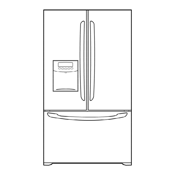
https://appliancetechmanuals.com 2. PARTS IDENTIFICATION Filter Dairy Bin Refrigerator Light Egg Box Refrigerator Shelves Modular Modular Door Bins Door Bins Wine Holder Super Fresh (Frequency Crisper with Model Only) Tilt-Out Modular Compartment Door Bins Cover Front Glide N Serve Adjust Cube Ice Maker Pull out Drawer Ice Bin... -
Page 5: Disassembly
https://appliancetechmanuals.com 3. DISASSEMBLY 3-1 REMOVING AND REPLACING REFRIGERATOR DOORS Removing Refrigerator Door ● w w CAUTION: Before you begin, unplug the refrigerator. Remove food and bins from doors. u u Left Door 1. Disconnect water supply tube by pushing back on the disconnect ring (4). 2. -
Page 6: Door
https://appliancetechmanuals.com 3-2 DOOR Door Gasket Replacement ● 1. Insert gasket bracket clips Door Gasket Removal ● 1) Insert gasket bracket edge beneath door frame edge. 1. Remove door frame cover 2) Turn upper gasket bracket spring so that the spring Starting at top of cover and working down, snap cover ends are in the door channel. -
Page 7: To Remove The Dispenser
https://appliancetechmanuals.com 2) Press gasket into channels on the three remaining 2. Pry off cover dispenser. sides of door. Figure 6 Figure 9 3. Replace door frame cover Starting at top of cover and working down, snap cover Disconnect wire harness. back into door. -
Page 8: Fan And Fan Motor
https://appliancetechmanuals.com 4. Make sure the bulbs are cool to the touch. 3-5 FAN AND FAN MOTOR Turn bulbs counterclockwise to remove. 1. Remove the freezer shelf. (If your refrigerator has an 5. Assemble in reverse order by snapping the Lamp Cover icemaker, remove the icemaker first) in, engaging the rear tabs followed by the front tabs. -
Page 9: Adjustment
https://appliancetechmanuals.com 4. ADJUSTMENT 4-1 COMPRESSOR 4-2-3 PTC-Applied Circuit Diagram Starting Method for the Motor ● 4-1-1 Role The compressor intakes low temperature and low pressure gas from the evaporator of the refrigerator and compresses OVERLOAD PROTECTOR this gas to high-temperature and high-pressure gas. It then delivers the gas to the condenser. -
Page 10: Olp (Overload Protector)
https://appliancetechmanuals.com 4-3 OLP (OVERLOAD PROTECTOR) 4-4 TO REMOVE THE COVER PTC 4-3-1 Definition of OLP (1) OLP (OVERLOAD PROTECTOR) is attached to the Compressor and protects the Motor by opening the circuit to the Motor if the temperature rises and activating the bimetal spring in the OLP. -
Page 11: Circuit Diagram
https://appliancetechmanuals.com 5. CIRCUIT DIAGRAM SEARS BEST MODEL - 11 -... -
Page 12: Troubleshooting
https://appliancetechmanuals.com 6. TROUBLESHOOTING 6-1 COMPRESSOR AND ELECTRIC COMPONENTS (Rated Voltage Remove PTC-Starter Power Source. ±10%)? from Compressor and measure voltage between Terminal C of Compressor and Terminals 5 or 6 of PTC. OLP disconnected? No Voltage. Replace OLP. Check connection condition. -
Page 13: Ptc And Olp
https://appliancetechmanuals.com 6-2 PTC AND OLP Normal operation of Separate PTC-Starter Observation value is Compressor is from Compressor and 115V/60Hz : 6.8Ω±30% measure resistance impossible or poor. between No. 5 and 6 of PTC-Starter with a Tester. (Figure 20) Replace PTC- The resistance value Starter. -
Page 14: Other Electrical Components
https://appliancetechmanuals.com 6-3 OTHER ELECTRICAL COMPONENTS ▼ Not cooling at all Check for open short or Compressor Cause incorrect resistance readings doesn't run. in the following components a. Starting devices Short, open, or broken. Poor contact b. OLP or shorted. Coil open or shorted. c. -
Page 15: Service Diagnosis Chart
https://appliancetechmanuals.com 6-4 SERVICE DIAGNOSIS CHART COMPLAINT POINTS TO BE CHECKED REMEDY No Cooling. • Is the power cord unplugged from the outlet? • Plug into the outlet. • Check if the power switch is set to OFF. • Set the switch to ON. •... -
Page 16: Refrigeration Cycle
https://appliancetechmanuals.com 6-5 REFRIGERATION CYCLE ▼ Troubleshooting Chart TEMPERATURE STATE OF STATE OF THE CAUSE REMARKS OF THE THE UNIT EVAPORATOR COMPRESSOR PARTIAL Freezer Low flowing sound of A little higher • Refrigerant level is low due LEAKAGE compartment and Refrigerant is heard and than ambient •... - Page 17 https://appliancetechmanuals.com 6-5-1 SEALED SYSTEM DIAGNOSIS “Not Cooling” Complaint All components operating, No airflow problems, Not frosted up as a defrost problem problem has been isolated to sealed system area Frost None Partial Pattern? Equalization Equalization Test Test Very Fast Very Slow Very Slow Very Fast Fast...
-
Page 18: Operation Principle & Repair Method Of Icemaker
https://appliancetechmanuals.com 7. OPERATION PRINCIPLE AND REPAIR METHOD OF ICEMAKER 7-1 OPERATION PRINCIPLE 7-1-1 Operation Principle of IceMaker Power On Start Position • Adjusts EJECTOR to Start Position with power on. Ice Making • Waits until water becomes cold after starting the Mode ice making operation. - Page 19 https://appliancetechmanuals.com 7-2 CONTROL METHOD ACCORDING TO FUNCTIONS 7-2-1 Start Position 1. After POWER OFF or Power Outage, check the EJECTOR's position with MICOM initialization to restart. 2. How to check if it is in place: - Check HIGH/LOW signals from HALL SENSOR in MICOM PIN. 3.
- Page 20 https://appliancetechmanuals.com 7-2-4 Fill / Park Position 1. Once a normal harvest mode has been completed, the water solenoid will be activated. 2. The amount of water is adjusted by pressing the water supply control S/W. This changes the time allowed for fill as illustrated in the chart.
- Page 21 https://appliancetechmanuals.com 7-2-5 Function TEST 1. This is a compulsory operation for TEST, SVC, cleaning, etc. It is operated by pressing the water supply control KEY for 3 seconds. 2. It operates in the Ice Making mode, but not in the Ice-Removing mode or water supply process. (If there is an ERROR, it can only be checked in the TEST mode.) 3.
-
Page 22: Description Of Function & Circuit Of Micom
https://appliancetechmanuals.com 8. DESCRIPTION OF FUNCTION & CIRCUIT OF MICOM 8-1 FUNCTION 8-1-1 Function 1. When the appliance is plugged in, it is set to “37” for Refrigerator and “0” for freezer. You can adjust the Refrigerator and the Freezer control temperature by pressing the ADJUST button. 2. - Page 23 https://appliancetechmanuals.com 8-1-6 CONTROL OF FREEZER FAN MOTOR 1. Freezer fan motor has high and standard speeds. 2. High speed is used at power-up, for express freezing, and when refrigerator is overloaded. Standard speeds is used for general purposes. 3. To improve cooling speed, the RPM of the freezer fan motor change from normal speed to high. 4.
- Page 24 https://appliancetechmanuals.com 8-1-10 Buzzer Sound When the button on the front Display is pushed, a Ding~ Dong~ sound is produced. 8-1-11 Defrost cycle 1. A defrost cycle will be initiated after 4 hours of accumulated compressor run time after the initial power up or a power failure.
- Page 25 https://appliancetechmanuals.com 8-1-13 Automatic Diagnosis Function 1. Automatic diagnosis makes servicing the refrigerator easy. 2. When an error occurs, the buttons will not operate; but the tones. such as ding. will sound. 3. When the error CODE removes the sign, it returns to normal operation (RESET). 4.
- Page 26 https://appliancetechmanuals.com 8-1-14 TEST Mode 1. The Test mode allows checking the PCB and the function of the components as well as finding out the defective part in case of an error. 2. The test mode is operated by pressing two buttons at Display panel. 3.
- Page 27 https://appliancetechmanuals.com 8-2 PCB FUNCTION 8-2-1 Power Circuit 1. Power is supplied to the control board at pin7 and 9 od connector #1. - 27 -...
- Page 28 https://appliancetechmanuals.com 8-2-2 Load / Buzzer Drive & Open Door Detection Circuit 1. Load Drive Condition Check To measure outputs of the control board, check voltages between the pins for the following components: Circuit Pin Number Pin Number Output Voltage Compressor Con2 pin11 Con1 pin1 115 VAC...
- Page 29 https://appliancetechmanuals.com 3. Open Door Detection Circuit Check 8-2-3 Temperature Sensor Circuit Measurement Pin 4 & 5 of con4 Ref.Door Location Freezer/ Pin 5 & 6 of con5 Fre.Door Refrigerator Door Closed Open RESISTANCE OF FREEZER RESISTANCE OF REFRIGERATOR & TEMPERATURE SENSOR DEFROST SENSOR &...
- Page 30 https://appliancetechmanuals.com 8-2-4 Refrigeration Compartment Stepping Motor Damper Circuit A reversible DC motor is used to open and close the damper. To open the damper, push test button once. To close the damper, push test button twice. - 30 -...
- Page 31 https://appliancetechmanuals.com 8-3 TROUBLESHOOTING PROBLEM INDICATED BY CHECK CHECKING METHOD CAUSE SOLUTION POWER 1. The whole 1. FREEZER/ Check if POWER SOURCE is Use boosting TRANS. SOURCE is DISPLAY REFRIGERATOR. FREEZER/REFRIGERA poor. poor. LED/SEVEN TOR DOOR IS OPEN SEGMENT and check display. DISPLAY is off.
- Page 32 https://appliancetechmanuals.com PROBLEM INDICATED BY CHECK CHECKING METHOD CAUSE SOLUTION COOLING is 1. If FREEZER Check is FREEZER Make sure the DOOR poor. REFRIGERATOR TEMPERATURE is TEMPERATURE is too isattached. TEMPERATURE normal. low. is too low. 2. If amount of cool air Make sure that the FAN MOTOR is poor.
- Page 33 https://appliancetechmanuals.com 8-4 MAIN PWB ASSEMBLY AND PARTS LIST 8-4-1 Main PWB Assembly Connector4 Connector6 Connector5 Connector1 Connector3 Connector2 - 33 -...
- Page 34 For the replacement parts, accessories and owner’s manuals that you need to do-it-yourself. refrigerator is found on the serial plate inside. 795.75192401 For Sears professional installation of home appliances and items like garage door openers and water heaters. 795.75199401 All repair parts listed are available 795.75194401...
- Page 35 https://appliancetechmanuals.com CASE PART S CAUTION: Use the part number to order part, not the position number. 207B 402A 103B 406C 271C 271B 103A 624C 410A 207A 409D 624A 624B 406D 501F 402A 624D 271B 271A 610B 503D 282F 410G 610B 610A 501A 409B...
- Page 36 https://appliancetechmanuals.com CASE PART S LOC No. 75193(ST) 75196(TI) 75192(SW) 75199(WB) 75194(BI) Description 103A 3650JA2113P 3650JA2113P 3650JA2061B 3650JA2113P 3650JA2061V HANDLE,BACK 103B 3650JA2113N 3650JA2113N 3650JA2061A 3650JA2113N 3650JA2061U HANDLE,BACK 103C 3550JJ0008F 3550JJ0008F 3550JJ0008A 3550JJ0008C 3550JJ0008B COVER,LOWER 105A 5251JA3003D 5251JA3003D 5251JJ2003D 5251JJ2003D 5251JJ2003D DRAIN ASSEMBLY,PIPE-Z 106A 4779JJ2001B 4779JJ2001B...
- Page 37 https://appliancetechmanuals.com FREEZ ER PART S CAUTION: Use the part number to order part, not the position number. 145C 136B 145F 248F 131A 237C 177B 136A LOC No. 7519* Description 131A 5075JJ2002C BANK ASSEMBLY,ICE 136A 3390JJ1073A TRAY,DRAWER 136B 3391JJ2010G TRAY ASSEMBLY,DRAWER 145C 4975JJ2007B GUIDE ASSEMBLY,RAIL...
- Page 38 https://appliancetechmanuals.com REFRI GERAT OR PART S CAUTION: Use the part number to order part, not the position number. 147C 141B 141A 147B 147A 141B 141A 141C 141B 141A 141C 141B 141A 141C 141D 141C 154B 161E 167B 154A 161A 161C 161D 161D 151C...
- Page 39 https://appliancetechmanuals.com REFRI GERAT OR PART S LOC No. 7519* Description 141A 5027JJ2014C SHELF ASSEMBLY,R 141B 5026JJ1051B SHELF,R 141C 5027JJ2012A SHELF ASSEMBLY,NET 141D 4890JL1012B GLASS, COVER-T/V 145D 3391JJ1030B TRAY ASSEMBLY,FRESH ROOM 145E 3550JL1011B COVER,TRAY 146B 4520JJ1004A LINK 147A 5074JJ1016A BANK,DAIRY 147B 3390JJ1082A TRAY,EGG 147C...
- Page 40 https://appliancetechmanuals.com DOOR PART S CAUTION: Use the part number to order part, not the position number. 230B 230A 241A 241B 231B 233B 233C 231A 233D 233A 241C 212G 237A 241C 237A 241C 244A 244B 241C 241C 262C 262C 312D 243A 243A 243B 243B...
- Page 41 https://appliancetechmanuals.com DI SPEN SER PART S 616B 279A 279B Only for service 143A 276A 113C 276B 403A 616A 406E 279C LOC No. 75193(ST) 75196(TI) 75192(SW) 75199(WB) 75194(BI) Description 113C 4970JJ3004A 4970JJ3004A 4970JJ3004A 4970JJ3004A 4970JJ3004A SPRING,W 143A 4620JA3026A 4620JA3026A 4620JA3026A 4620JA3026A 4620JA3026A STOPPER,SLIDE 276A...
- Page 42 https://appliancetechmanuals.com...
Need help?
Do you have a question about the 795.75192401 and is the answer not in the manual?
Questions and answers