Table of Contents
Advertisement
Quick Links
Advertisement
Table of Contents
Troubleshooting

Related Manuals for Topcon Motorgrader


Summary of Contents for Topcon Motorgrader
- Page 3 Rev. E ©Copyright Topcon Positioning Systems March, 2007 All contents in this manual are copyrighted by Topcon. All rights reserved. The information contained herein may not be used, accessed, copied, stored, displayed, sold, modified, published, or distributed, or otherwise reproduced...
- Page 4 ECO#2955...
-
Page 5: Table Of Contents
Table of Contents Preface ..............v Chapter 1 System Overview ..........1-1 Control Box ..............1-3 Remote “Smart” Knobs ........... 1-4 Sonic Tracker II ............... 1-5 Laser Tracker and Trackerjack ........1-6 Blade Slope Sensor ............1-7 Rotation Sensor ..............1-8 Mainfall Sensor .............. - Page 6 Grading a City Street ............5-31 Grading from Curbs ............5-36 Grading From Curbs Placed at Different Elevations ..5-39 Road Widening and Shoulders ......... 5-44 Grading On Curves ............5-46 Grading Slope Transitions ..........5-48 Motorgrader System Five Operator’s Manual...
- Page 7 Table of Contents Chapter 6 Maintenance ............6-1 Preventative Maintenance & Daily Care ......6-1 Transducer Cleaning (Sonic Tracker II) ......6-2 Transducer Replacement Procedure (Sonic Tracker II) .. 6-3 Sonic Tracker II Transducer Replacement ....6-3 Rotation Sensor Cleaning and Lubrication ...... 6-7 Cleaning the Rotation Sensor ........
- Page 8 Table of Contents Notes: Motorgrader System Five Operator’s Manual...
-
Page 9: Preface
The sections provided in this manual include information necessary for the correct operation, care and trouble- shooting of your TOPCON System Five. Also contained in this manual is a selection of WARNINGS, CAUTIONS, and NOTICES you should become familiar with to safely operate the system. - Page 10 TOPCON reserves the right to make product changes at any time without notice. Comments, suggestions, and questions about TOPCON products are welcomed. Contact your local TOPCON representative or a representative at our corporate facility.
-
Page 11: Chapter 1 System Overview
Chapter 1 System Overview Your TOPCON Grader Control System Five™ is a versatile tool that combines Elevation and Cross Slope Control into a package powerful enough for your most demanding jobs, yet convenient enough to use everyday. In fact, System Five is so easy to learn that your benefits will start immediately: •... - Page 12 System Overview Figure 1-1. Motorgrader System Five Operator’s Manual...
-
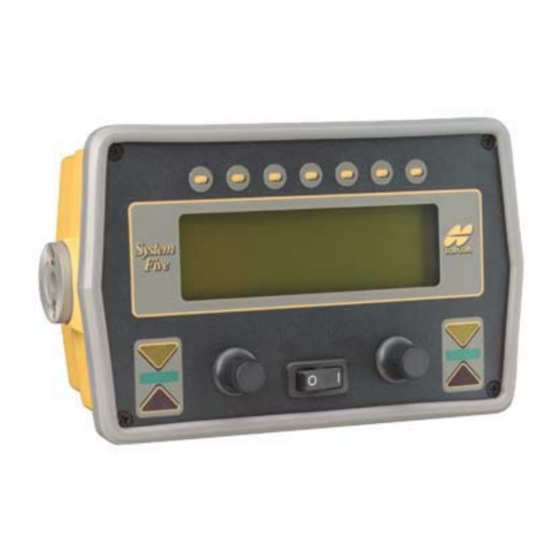
Page 13: Control Box
Control Box Control Box The Control Box is the operator's interface to System Five. It easily attaches to its mounting bracket with one clamp, and at the end of the day can be quickly removed for storage. The control box connects to the Remote "Smart"... -
Page 14: Remote "Smart" Knobs
The knobs allow the operator to perform several Control Box functions while keeping his hands where they belong - on the levers. LEFT KNOB RIGHT KNOB Auto Auto Manual Manual Swap Set Point Raise Raise Lower Lower Survey Survey Figure 1-3. Motorgrader System Five Operator’s Manual... -
Page 15: Sonic Tracker Ii
Sonic Tracker II Sonic Tracker II The Sonic Tracker II measures and controls the elevations of the moldboard. A transducer, located in the bottom of the Sonic Tracker II™, generates sound pulses like a speaker and listens for returned echoes like a microphone. The Tracker measures the distance, and controls grade from a physical grade reference, such as a curb, stringline, or existing road surface. -
Page 16: Laser Tracker And Trackerjack
The Laser Trackerjack should be removed at the end of each day and stored in its carrying case. A vibration pole storage bracket can be attached to the back of the grader for use when the Trackerjack system is not needed. OPTIONAL LS-B Figure 1-5. Motorgrader System Five Operator’s Manual... -
Page 17: Blade Slope Sensor
The Blade Slope Sensor will measure slopes from +20% to -20%. There is an option for a steep slope sensor that will measure up to +/- 100% slope. The Blade Slope Sensor is sealed and once attached to the motorgrader should not be removed. Figure 1-6. P/N 7010-0344... -
Page 18: Rotation Sensor
The Rotation Sensor is a sealed unit and contains no adjustments. Once attached to the machine it should not be removed, other than for periodic maintenance (refer to Maintenance Section of this manual). Figure 1-7. Motorgrader System Five Operator’s Manual... -
Page 19: Mainfall Sensor
Mainfall Sensor Mainfall Sensor The Mainfall Sensor uses the same type of precision electronic device that is used by the Blade Slope Sensor. It mounts under the Hydraulic Manifold Assembly and measures the slope of the machine in the direction of machine travel. The Mainfall Sensor is a sealed unit and contains no manual adjustments. -
Page 20: Hydraulic Manifold Assembly
The Hydraulic Manifold Assembly is a sealed unit and contains no adjustments. Once attached to the machine, it should not be removed. Figure 1-9. Motorgrader System Five Operator’s Manual 1-10... -
Page 21: Carrying Case
Carrying Case Carrying Case A Carrying Case is provided with each System Five. The Carrying Case is lined and includes pre-cut sections for each Sonic Tracker II and the Control Box. A cut-out section is also provided for storing coil cords. At the end of the day, always wipe down each of the components and place them and the coil cords in the appropriate sections for storage. - Page 22 System Overview Notes: Motorgrader System Five Operator’s Manual 1-12...
-
Page 23: Chapter 2 Operation
Chapter 2 Operation This chapter reviews System Five's components and explains the function of each. NOTICE NOTICE When operating in rainy weather or in wet conditions, the Control Box, Sonic Tracker II's, and cables must be thoroughly dried BEFORE placing them in the Carrying Case at the end of the day. -
Page 24: Control Box Front Panel Switches And Controls
A uto A uto 1. LCD Display 2. Left and Right Grade Adjustment LED's 3. Left and Right Automatic Operation Indicators 4. Left and Right Grade Adjustment Knob 5. Power Switch 6. Function Buttons Figure 2-1. Motorgrader System Five Operator’s Manual... -
Page 25: The Lcd (Liquid Crystal Display)
The LCD allows the operator to view text and graphic symbols that represent elevation or slope settings that System Five is currently maintaining for the left and right sides of the motorgrader. • System Five in Control Mode during operation. -
Page 26: Left And Right Grade Adjustment Leds
Operation Left and Right Grade Adjustment LEDs Figure 2-5. Motorgrader System Five Operator’s Manual... -
Page 27: Left And Right Automatic Operation Indicators
Control Box Left and Right Automatic Operation Indicators These LED's illuminate with the word "Auto" when the Right and/or Left Auto/Manual switch Smart Knobs are used to switch System Five to Automatic Operation. Left and Right Grade Adjustment Knobs These knobs are used to make measured adjustments to the cross slope or elevation settings. -
Page 28: Grade Adjustment Direction Arrows
On Grade. • Rotate the knob counter-clockwise to reach grade. • Rotate the knob clock wise to reach grade. AUTO Figure 2-8. Power Switch Push the switch to turn the box on or off. Motorgrader System Five Operator’s Manual... -
Page 29: Function Buttons
Control Box Function Buttons When pushed these buttons activate the function shown on the screen directly below. Control Box Operation — MENU TRIM GAIN System System System System System System 0.0% Five Five Five Five Five Five C ontrol 3D-M C S etup CONTROL MODE MAIN MENU... -
Page 30: Control Mode
LCD from Elevation Mode to Slope Mode and vice versa. — MENU TRIM TRIM GAIN 2.0% 2.0% CONTROL MODE — MENU TRIM GAINS System System System System System System 2.0% Five Five Five Five Five Five CONTROL MODE Figure 2-12. Motorgrader System Five Operator’s Manual... - Page 31 Control Box — MENU TRIM GAIN 2.0% CONTROL MODE — MENU TRIM TRIM GAIN System System System System System System 2.0% 2.0% Five Five Five Five Five Five CONTROL MODE Figure 2-13. – • Slope Direction Pressing the Slope Direction button will change the direction of the slope, regardless of what side slope is being used.
- Page 32 KNOB TO G ET T HE BLADE TO M ATCH BLADE WEAR CAL (TRIM) — MENU TRIM GAINS System System System System System System 2.0% Five Five Five Five Five Five CONTROL MODE Figure 2-15. Motorgrader System Five Operator’s Manual 2-10...
- Page 33 Control Box • Set (Elevation Control Only) Pressing the Set button will allow the operator to set the elevation grade reference number to any value desired. This does not change the elevation, it only changes the reference number displayed on the Control Box. (Refer to Setting Reference Number section within this manual).
- Page 34 — MENU TRIM GAIN System System System System System System 2.0% Five Five Five Five Five Five CONTROL MODE A uto A uto Figure 2-17. Motorgrader System Five Operator’s Manual 2-12...
-
Page 35: Remote "Smart" Knobs
Control Box Once Gain adjustments have been complete, push "ENTER". ENTER System System System System System System 2.0% Five Five Five Five Five Five ADJUST GAIN A uto A uto TURN THIS KNOB TO TURN THIS KNOB TO ADJUST ELEVATION GAIN ADJUST CROSS SLOPE GAIN Figure 2-18. - Page 36 Allows operator to switch the blade between Automatic and Manual. Push the switch outward for Automatic Control. If both sides of the motorgrader are in slope mode then only one "Auto" indicator LED will illuminate consistantly when System Five is switched to Automatic Operation.
- Page 37 Control Box – Sonic Tracker: switches the side of the machine controlling elevation. This is commonly used when turning the machine around at the end of a pass. Hold switch in for 1 second and swap occurs. A single beep tone is heard when swap occurs.
-
Page 38: 3Dmc Mode
Setup Mode is used for Calibration, System Setup, and advanced features of System Five. EXIT ENTER S etup CALIBRATION ADJUST LED BRIGHTNESS SET POINTS SYSTEM TEST MEASUREMENT UNIT BEEPER CHECK HOURMETERS MACHINE SETUP Figure 2-21. Motorgrader System Five Operator’s Manual 2-16... - Page 39 Control Box • Calibration Why do you need to calibrate? Although System Five does not usually require maintenance or adjustment, the grader it is attached to does. All the moving parts on your grader wear at different rates. In order for System Five to work correctly, it has to be "told"...
- Page 40 LED's on the faceplate of the box. 4. Press the "ENTER" button to save the settings. BACKLIGHT BACKLIGHT EXIT ENTER BRIGHT THIS KNOB ADJUST THESE CONTROL THE LED BRIGHTNESS THE BACKLIGHT ADJUST LED BRIGHTNESS Figure 2-25. Motorgrader System Five Operator’s Manual 2-18...
- Page 41 Control Box • System Test This is a diagnostic test for all of the components that make up the system. The Control Box will indicate if the device is in use and if it is properly working (Refer to Troubleshooting section). EXIT ENTER KNOB...
-
Page 42: Sonic Tracker Ii
The Sonic Tracker II attaches to the system through one quick connect cable and attaches to the machine with a single bolt. At the end of the day, Tracker should be removed for proper storage in the carrying case. onic racker Figure 2-27. Motorgrader System Five Operator’s Manual 2-20... - Page 43 Sonic Tracker II The Sonic Tracker II measures the distance to a physical grader reference by sending out sound pulses 39 times per second. As soon as the Tracker sends out a sound wave it starts a stop watch. The sound waves go down, bounce off of any physical reference, and are reflected back to the Tracker.
- Page 44 ON G RADE BLINKING DOWN ARROW/ON G RADE BLINKING DOWN ARROW SOLID DOWN ARROW SLOW BLINKING DOWN ARROW NO CORRECTION COARSE FINE MADE CORRECTION CORRECTION (OUT OF (AUTOMATIC) (AUTOMATIC) WORKING WI NDOW) Figure 2-29. Motorgrader System Five Operator’s Manual 2-22...
- Page 45 Sonic Tracker II On the grader the Sonic Tracker II will be positioned above the grade reference. Its job is to maintain the exact distance from the tracker to the grade reference, keeping the Tracker On Grade. If the Tracker is On Grade, the cutting edge will be at the desired grade.
- Page 46 The Tracker and Control Box will indicate a down correction arrow, and lower hydraulic valve corrections will be applied to bring the Tracker back to On Grade. STOPWATCH On Grade onic racker GRADE REFERENCE DESIRED GRADE Figure 2-31. Motorgrader System Five Operator’s Manual 2-24...
- Page 47 Sonic Tracker II If the moldboard and Tracker are lowered the stop watch will be stopped at a shorter time. The Tracker and Control Box will indicate a raise correction arrow, and raise hydraulic valve corrections will be applied to bring the Tracker back to On Grade. STOPWATCH On Grade onic...
- Page 48 The Tracker is out of the Working Window, and no On Grade correction signals will be applied. STOPWATCH On Grade SLOW BLINKING CORRECTION SIGNALS onic racker STRINGLINE REFERENCE DESIRED GRADE Figure 2-33. Motorgrader System Five Operator’s Manual 2-26...
- Page 49 Sonic Tracker II If the Tracker sees an obstruction closer than the reference signal, such as a grade pin, the sound waves do not take as long to come back and the stop watch is stopped much sooner. The Tracker is out of the Working Window, and no On Grade correction signals will be applied.
- Page 50 As the Tracker is moving farther away from the grade reference the sonic footprint or cone will increase in size. SONIC "FOOTPRINT" onic racker 2.0' 6.0" Figure 2-35. Motorgrader System Five Operator’s Manual 2-28...
- Page 51 Sonic Tracker II The Tracker has a total working range of 14 inches to 55 inches—41 inches of adjustment! This allows the Tracker to be set over a stringline or choker on one pass, then match grade on the next pass without moving the tracker.
-
Page 52: Laser Control
When the laser beam is in the center of the receiver, it indicates an On Grade signal. Figure 2-37. Motorgrader System Five Operator’s Manual 2-30... - Page 53 Laser Control As the blade is raised, the beam of light hits the Laser Receiver below the center and a lower signal is indicated. Figure 2-38. P/N 7010-0344 2-31...
- Page 54 Operation As the blade is lowered the beam of light hits the Laser Receiver above the center a raise signal is indicated. Figure 2-39. Motorgrader System Five Operator’s Manual 2-32...
-
Page 55: Slope Control
Slope Control Slope Control System Five uses 3 sensors to measure and cut the desired slope perpendicular to the edge of the road. • Blade Slope Sensor A blade slope sensor is mounted to the back of the circle. It contains an electronic level vial, which acts as a precision carpenters level. - Page 56 Mainfall Sensor measures the slope of the machine going up-hill or down. When the blade is rotated, the mainfall prevents the leading edge from undercutting when going uphill and the trailing edge from undercutting when going downhill. Figure 2-42. Motorgrader System Five Operator’s Manual 2-34...
- Page 57 Slope Control The operator just dials in the desired slope of the project, and the system will cut the desired slope perpendicular to the edge of the road, regardless of the blade angle or going up or down hills. The operator can rotate the blade on the fly, and System Five will automatically compensate to cut the correct cross slope.
- Page 58 Operation Notes: Motorgrader System Five Operator’s Manual 2-36...
-
Page 59: Chapter 3 Calibration
Chapter 3 Calibration EXIT ENTER CALIBRATION ADJUST LED BRIGHTNESS SET POINTS SYSTEM TEST MEASUREMENT UNIT BEEPER CHECK HOURMETERS MACHINE SETUP Figure 3-1. Why do you need to calibrate? Although System Five does not usually require maintenance or adjustment, the grader it is attached to does. All the moving parts on your grader wear at different rates. -
Page 60: Calibrate Rotation
Rotate blade to chisel marks. CALIBRATE ROTATION Figure 3-3. 1. Rotate the blade to the chisel marks on the "A"-frame assembly provided by installer. 2. Push the "ENTER" button and the Rotation Sensor Calibration is completed. Figure 3-4. Motorgrader System Five Operator’s Manual... -
Page 61: Calibrate Mainfall
Calibrate Mainfall Calibrate Mainfall The Main Slope (Mainfall) Sensor bolted to the frame of the machine measures the slope of machine travel, up hill and down. Tire wear is the primary reason for occasional Mainfall Sensor Calibration. To perform the Mainfall Sensor Calibration: 1. - Page 62 Push the "ENTER" button. 4. Wait 5 seconds until you hear a double beep, and the calibration is complete. ENTER Turn machine around over previous marks. CALIBRATE MAINFALL Figure 3-6. Motorgrader System Five Operator’s Manual...
-
Page 63: Calibrate Blade
Calibrate Blade Calibrate Blade The Blade Slope Sensor, bolted to the back of the machine's circle assembly, measures the slope of the cutting edge. Cutting edge wear is the reason for Blade Sensor Calibration. To perform the Blade Slope Sensor Calibration: 1. - Page 64 Slope Sensor has been removed. After this calibration has been completed, always perform the Blade Wear (Trim) Calibraton as your are cutting grade to make a fine calibration adjustment. Motorgrader System Five Operator’s Manual...
-
Page 65: Blade Wear Calibration (Trim)
Blade Wear Calibration (Trim) Blade Wear Calibration (Trim) The Blade Wear Calibration allows the operator to make an adjustment for cutting edge wear. This calibration adjustment is performed while cutting grade right on the job, and can be completed in less than 5 minutes. This will insure a perfect calibration and verifies System Five is cutting exactly the way it is supposed to. - Page 66 Press the "NEXT" button. EXIT NEXT TURN AROUND AND STOP 2.0% OVER PREVIOUS PASS. IN AUTO CHECK IF CUTTING EDGE MATCHES. BLADE WEAR CAL. (TRIM) Figure 3-10. Motorgrader System Five Operator’s Manual...
- Page 67 Blade Wear Calibration (Trim) 3. If the cutting edge matches, no adjustment is needed. Press the "ENTER" button. If the cutting edge does not match, turn the right grade adjustment knob to get it to match. Press the "ENTER" button, and the Blade Trim Calibration is complete. —...
-
Page 68: Adjust Valve Offsets
ENTER MENU TRIM G ains TURN AROUND AND STOP 2.0% 0.0% OVER PREVIOUS PASS. IN AUTO CHECK IF CUTTING LEFT RIGHT EDGE MATCHES. ADJUST VALVE OFFSETS BLADE WEAR CAL. (TRIM) CONTROL MODE Figure 3-12. Motorgrader System Five Operator’s Manual 3-10... -
Page 69: Manual Adjusment
Adjust Valve Offsets Manual Adjusment If the operator wants to make an adjustment or just verify that the Valve Offset Values are correct, a "Manual" Valve Offset Calibration can be performed. 1. Press the "Raise" button on the left hand side. Rotate left hand knob, raising or lowering the Raise Offsets. -
Page 70: External Switches
Selects program to operate the Simple Switch (System Four Type Switches). • Auto Select Automatically determines which device (SmartKnob or Simple Switch) is connect to System Five System. The appropriate program is then selected to operate the device. Motorgrader System Five Operator’s Manual 3-12... -
Page 71: Getting Ready To Grade
Chapter 4 Getting Ready to Grade Control Box Setup To prevent theft or vandalism, the Control Box has been designed for quick removal at the end of the day. To install the Control Box, just bolt it on with the hand knob and connect the two quick-disconnect electrical connectors. -
Page 72: Checking Cross Slope (Trim Calibration)
KNOB TO G ET T HE BLADE TO M ATCH BLADE WEAR CAL (TRIM) — MENU TRIM GAIN System System System System System System 2.0% Five Five Five Five Five Five CONTROL MODE A uto A uto Figure 4-2. Motorgrader System Five Operator’s Manual... -
Page 73: Sonic Tracker Setup
Sonic Tracker Setup Sonic Tracker Setup When installing and positioning the Sonic Tracker II, first, connect the coil cord to the Tracker. Bolt the Tracker to the bracket, and visually check to get the "L"-Bar and Tracker plumb. Make one wrap of the coil cord around the "L"- Bar. This will act as a strain relief for the connector on the Tracker. - Page 74 When tracking multiple references, for example, elevated string on one pass then matching grade on the next pass, consider the Tracker position so it works for both applications without having to move the Tracker. Figure 4-4. Motorgrader System Five Operator’s Manual...
- Page 75 Sonic Tracker Setup The closest the Tracker can be set to the grade reference is 14 inches. onic racker 14.0" MINIMUM DISTANCE Figure 4-5. The farthest the Tracker can be set from the grade reference is 55 inches. onic racker 55.0"...
- Page 76 Tracker should be over the stringline. onic racker 18.0" to 30.0" RECOMMENDED DISTANCE STRINGLINE REFERENCE EDGE OF ROAD TO STRINGLINE Figure 4-7. Motorgrader System Five Operator’s Manual...
- Page 77 Sonic Tracker Setup When tracking an existing road, position the Tracker 14 - 30 inches. This will leave enough distance to adjust the Working Window to On Grade when the blade is moved over to match the first pass. onic racker 14.0"...
- Page 78 When tracking a curb, lower the tracker so it is just picking up the lip of the curb. This will keep it from picking up the top of curb or obstructions in the gutter. Figure 4-10. 14.0" to 18.0" RECOMMENDED DISTANCE CURB Figure 4-11. Motorgrader System Five Operator’s Manual...
-
Page 79: Setting The Reference Number
Setting the Reference Number Setting the Reference Number For most Sonic Tracker applications, it is best to set the reference number so when the cutting edge is matching a pass, the number reads 0.00. In this case, the blade is not cutting or filling, so it makes sense that the number reads 0.00. - Page 80 Control Mode. Repeat these steps for the Sonic Tracker on the other side. EXIT — — ENTER ZERO MENU MENU TRIM G ains GAIN 0.0% SET ELEVATION RIGHT CONTROL MODE CONTROL MODE Figure 4-15. Motorgrader System Five Operator’s Manual 4-10...
- Page 81 Setting the Reference Number When setting the Tracker reference number, be aware of cutting edge wear common at the edges of the blade. Setting to 0.00, with the tip of the blade on the ground, would cause the blade to undercut farther in from the edge.
-
Page 82: Laser Receiver Setup
Place the Trackerjack on the vibration pole so the four wheels slide into the slots at the bottom of the pole. Push the manual raise button on the Trackerjack to raise it up the pole. M agnetic S ensor Figure 4-17. Motorgrader System Five Operator’s Manual 4-12... - Page 83 Laser Receiver Setup Raise the Trackerjack so that it's magnetic pickup sensor is above the magnet on the bottom of the vibration pole. Once the sensor is above the magnet, the operator can not accidentally lower the Trackerjack off the pole using the grade adjustment knob on the Control Box. Another magnet at the top of the vibration pole acts as an upper limit, keeping the Trackerjack from climbing off the top of the pole.
- Page 84 Then place the grade rod on the reference hub and move the detector up or down to lock on the laser beam. Adjust the rod for cut/fill or known elevation of the reference hub. LS-70A LASER POWER LEVEL R.P.M. POWER Figure 4-20. Motorgrader System Five Operator’s Manual 4-14...
- Page 85 Laser Receiver Setup Set both sides of the cutting edge on the ground, and raise or lower the receiver to get an On-Grade signal. This can be done by just pushing the two red buttons on the Smart Knobs, and the Trackerjack will search up and down the vibration pole and lock onto the laser beam.
- Page 86 MENU MENU EXIT ZERO GAINS GAINS ENTER G ains System System System 0.0% 0.0% 5.65 2.0% 2.0% Five Five Five CONTROL MODE CONTROL MODE CONTROL MODE CONTROL MODE A uto A uto Figure 4-24. Motorgrader System Five Operator’s Manual 4-16...
- Page 87 Laser Receiver Setup 2. Setting the reference number to 0.00: This is typically used for jobs with slope although it can be used on flat pads as well. If the cutting edge is .15 feet above finish grade, then set the display to read .15 feet. The operator can then dial in a desired height above grade while roughing in, then dial down to 0.00 for finish grade.
-
Page 88: Using Set Points
MACHINE SETUP Figure 4-26. Turn the right Control Box knob to enter the number of set points desired for your job application. EXIT ENTER Enter number of Set Points desired. MACHINE SETUP Figure 4-27. Motorgrader System Five Operator’s Manual 4-18... - Page 89 Using Set Points After returning to Control Mode, the center of the LCD will display the number of Set Points entered and which one is currently being used. — — — — MENU TRIM G ains MENU MENU MENU TRIM TRIM TRIM GAINS...
- Page 90 Getting Ready to Grade CUT GRADE 1.90' BELOW THE SONIC STRINGLINE 2.0% SLOPE VIEW FROM BEHIND GRADER Figure 4-30. Motorgrader System Five Operator’s Manual 4-20...
- Page 91 Using Set Points For the next pass, the right side needs to be set to match the previous pass. Push the Set Point switch, and then dial the Sonic Tracker II to 0.00, while keeping the cross slope at and the cross slope to 2.0%. MATCH THE PREVIOUS PASS 2.0% SLOPE...
- Page 92 — — MENU TRIM G ains MENU MENU MENU TRIM TRIM TRIM GAINS GAINS GAIN -1.00 -.95 0.0% 2.0% 1.95 2.0% 2.0% CONTROL MODE CONTROL MODE CONTROL MODE CONTROL MODE CONTROL MODE Figure 4-32. Motorgrader System Five Operator’s Manual 4-22...
-
Page 93: Grading Applications
Chapter 5 Grading Applications Sonic Stringline Figure 5-1. Setting Up a Sonic Stringline On a typical project, hubs or laths, offset from the edge of the road, provide the grade information for the operator. This information needs to be transferred from the ground to the operator. This is commonly done by a grade setter using a hand level, a 4 man crew pulling a string across the road and marking cuts, placing "blue tops"... - Page 94 Stringline Laser Bracket NOTICE NOTICE Although Topcon's Sonic Tracker will work with many sizes and types of stringline, for best results we recommend 1/8 inch diameter nylon stringline. If the Tracker will track the ground, but will not track a 1/8 inch diameter stringline, clean or replace the transducer.
- Page 95 Sonic Stringline 1. Place the Sonic Grade Clips on stakes and drive the stakes approximately 6 to 8 inches away from, but in line with, the hubs (Do Not disturb the hubs). GRADE CLIP STAKE STAKE Figure 5-2. P/N 7010-0344...
- Page 96 4. Decide what the Sonic Stringline hike-up (the distance from Finished Grade to the Sonic Stringline) should be: in this case, 2 feet. Make a cut/fill lath using a lath and a Topcon Cut/Fill Decal. Motorgrader System Five Operator’s Manual...
- Page 97 Sonic Stringline Measure, from the bottom of the lath, the desired hike-up and make a mark at that point. Place the Cut/Fill Decal on the lath with "0" on the point you marked. LATH 2.0' SET "0" ON DECAL AT 2.0' MARK FROM LATH BOTTOM OF LATH Figure 5-4.
- Page 98 Grading Applications • The stringline is now set to 2 feet above finished grade. 2.0' 2.0' OFFSET 2.0% Figure 5-6. • Repeat this process at each station before starting to grade. Figure 5-7. Motorgrader System Five Operator’s Manual...
-
Page 99: Setting Stringline To Projected Slope
Sonic Stringline Setting Stringline to Projected Slope Jobs with slope transitions or super-elevations must have the stringline set to the "projected slope". Failure to do this will produce an elevation error at the edge of the road as the slope is changed. To set the stringline to the projected slope, first set up the string at the desired hike up as shown in the previous pages. - Page 100 First, mark the lath with a 2 or 3 feet "hike up" or boot" above grade, just as you would to check grade with an eye level or pulling a string across the street. Figure 5-10. Motorgrader System Five Operator’s Manual...
- Page 101 Sonic Stringline Secure an anchor pin at each end of the stringline and pull the stringline tight. At each station, staple or ty-rap the stringline directly to the witness lath so the stringline is at the desired hike-up. Figure 5-11. Due to the height of some stakes the Tracker may need to be raised or the tops of those stakes may need to be cut off.
-
Page 102: Making A Grade Verification Lath
In this example assume that the hub offset from the edge of road is 1.5 feet and that the "hike-up" is 2.0 feet. Construct a Grade Checking Lath as shown below. 1 . 5 1 . 5 I L S 2 . 0 Figure 5-12. Motorgrader System Five Operator’s Manual 5-10... -
Page 103: Verifying Grade
Sonic Stringline Verifying Grade To verify grade, set the Grade Checking Lath on the edge of the graded area so that the level bubble extends over the Sonic Stringline shown below. 1 . 5 STRINGLINE STRINGLINE FINISHED GRADE FINISHED GRADE APPROX. -
Page 104: Laser Grade Checking System
Set the laser on the Stringline Laser Bracket and place the bracket on the Sonic Grade Clip. The automatic leveling laser will produce a "stringline" of laser light across the road at the same height as the stringline. 2.0' 2.0% Figure 5-14. Motorgrader System Five Operator’s Manual 5-12... - Page 105 Sonic Stringline To inspect grade, use the laser detector and the cut/fill lath or folding rule. At the edge of the road, finished grade is the same as the stringline hike-up. Any cuts or fills are immediately measured on the lath or folding rule.
- Page 106 Because of the consistent grade cut by System Five, you will find you do not need to inspect grade at every station, but you should "spot "check" grade at several stations. Figure 5-18. Motorgrader System Five Operator’s Manual 5-14...
-
Page 107: Grading A Road Using A Stringline
Grading a Road Using a Stringline Grading a Road Using a Stringline In this example, a Sonic Stringline has been set 2.0' above the desired finished sub-grade. Desired cross slope is 2.0%. SONIC STRINGLINE 2.0% 2.0% SLOPE SLOPE 2.0' BELOW SONIC STRINGLINE Figure 5-19. - Page 108 When beginning to cut grade, it is likely that the rough subgrade is several inches above grade. To start, set the cutting edge down on the existing grade with the Tracker positioned over the stringline. 2.0% SLOPE STRINGLINE VIEW F ROM BEHIND G RADER Figure 5-20. Motorgrader System Five Operator’s Manual 5-16...
- Page 109 Grading a Road Using a Stringline Press both red buttons on the Smart Knob to set the Tracker to On- Grade. The Control Box will then read the depth of cut below the stringline at that location. In this example, the display indicates that the cutting edge is 1.65 feet below the stringline.
- Page 110 "pioneering" pass. Depending upon the material conditions and amount of cut along the road. — MENU TRIM GAIN 2.0% 1.70 CONTROL MODE CUT GRADE 1.70' BELOW THE SONIC STRINGLINE WINDROW 2.0% SLOPE VIEW FROM BEHIND GRADER Figure 5-22. Motorgrader System Five Operator’s Manual 5-18...
- Page 111 Grading a Road Using a Stringline Be sure to check the grade several times in the first 50 feet. Depending on how accurate the Tracker and the stringline offset from the edge of the road were "zeroed out", the grade may not be exactly 1.70 feet below the stringline.
- Page 112 This avoids backing up to use the Tracker only on one side. CUT GRADE TO MATCH THE PREVIOUS PASS Figure 5-26. Motorgrader System Five Operator’s Manual 5-20...
- Page 113 Grading a Road Using a Stringline Now go back to the stringline and make another pass, dialing in an additional cut. Since the last pass was cut at 1.70 feet, dialing to -1.80 would produce a .10 foot cut. With the cross slope system maintaining a 2.0% slope, the ENTIRE moldboard will be cutting .10 foot.
- Page 114 — MENU TRIM GAIN 2.0% 0.00 CONTROL MODE VIEW FROM BEHIND GRADER SONIC STRINGLINE 2.0% SLOPE — MENU TRIM GAIN 2.0% 2.00 CONTROL MODE VIEW FROM BEHIND GRADER 2.0% SLOPE SONIC STRINGLINE Figure 5-28. Motorgrader System Five Operator’s Manual 5-22...
- Page 115 Grading a Road Using a Stringline — MENU TRIM GAIN 2.0% 0.00 CONTROL MODE VIEW FROM BEHIND GRADER SONIC STRINGLINE 2.0% SLOPE Figure 5-29. Once to grade, carry the material on this side of the road at least 1 1/2- 2 feet past the centerline.
- Page 116 WITH SPRAY CAN 2.0% 2.0% SLOPE SLOPE Figure 5-31. Finished grade can be carried over the centerline by tracking the pass on the opposite side. 2.0% SLOPE VIEW F ROM BEHIND G RADER Figure 5-32. Motorgrader System Five Operator’s Manual 5-24...
- Page 117 Grading a Road Using a Stringline Position the grade to make the pass by setting the edge of the moldboard so it is about 1 1/2-2 feet past the centerline. To keep the material from spilling out from the leading edge, rotate the moldboard to a fairly steep angle.
- Page 118 0.00. Switch to Automatic Control and continue grading. Verify the grade and make small adjustments as necessary. onic racker onic racker — MENU TRIM GAIN 2.0% 0.12 CONTROL MODE Figure 5-35. Motorgrader System Five Operator’s Manual 5-26...
- Page 119 Grading a Road Using a Stringline While grading, it is important to drive straight to keep the Tracker positioned over the same "path" on the opposite slope. Steering left or right will cause the Tracker to "ride up" or "ride down" the slope, causing an elevation error at the centerline.
- Page 120 TOP VIEW OF GRADER SLOPE CONTROL EDGE OF ROAD SONIC CONTROL Figure 5-39. Motorgrader System Five Operator’s Manual 5-28...
- Page 121 Grading a Road Using a Stringline To accomplish this, the Tracker will need to be repositioned so the sound waves will not pick up the window at the end of the blade. Set the blade on a smooth, previously graded pass so that the cutting edge is just touching the ground.
- Page 122 Set the Tracker to on-grade, and grade the pass along the edge of the road. onic racker Figure 5-42. — MENU GAIN TRIM 2.0% 0.00 CONTROL MODE RIGHT SONIC STRINGLINE 2.0% 2.0% SLOPE SLOPE VIEW FROM BEHIND GRADER Figure 5-43. Motorgrader System Five Operator’s Manual 5-30...
-
Page 123: Grading A City Street
Grading a City Street After the windrow is picked up, Sonic Control on both sides may be used to make a final "clean up" pass after the scraper or loader. — MENU GAIN 0.00 0.00 CONTROL MODE Figure 5-44. Grading a City Street This section reviews how to cut sidewalk, curb, and street grade, as well as cutting a crowned street from existing curb. - Page 124 Once the sidewalk grade has been cut and verified, mark the edge of the sidewalk with spray paint to make it visible for the operator. SONIC STRINGLINE LEFT SONIC MARK LEFT EDGE STRINGLINE OF SIDEWALK WITH SPRAY CAN 2.0% SLOPE Figure 5-47. Motorgrader System Five Operator’s Manual 5-32...
- Page 125 Grading a City Street Next use the sidewalk grade as a reference to cut the curb grade. Dial in the desired grade and slope. — MENU TRIM GAIN 6.0% 0.75 CONTROL MODE 6.0% LEFT SONIC SLOPE STRINGLINE 3.5' VIEW FROM BEHIND GRADER Figure 5-48.
- Page 126 Use the curb grade as a reference to cut the street grade. Dial in thedesired grade and slope. — MENU GAIN TRIM 2.0% 0.20 CONTROL MODE 2.0% SLOPE LEFT SONIC STRINGLINE VIEW FROM BEHIND GRADER Figure 5-51. Motorgrader System Five Operator’s Manual 5-34...
- Page 127 Grading a City Street For best results, stay about 6 inches in from the paint marks on the “rough in” passes to avoid material spilling onto the curb grade. Continue to grade the street across the centerline. Grade the opposite sidewalk curb, and street section and the project is complete.
-
Page 128: Grading From Curbs
25-50 feet. Remember, it is always best to start with the grade high, then "trim" down on the next pass. — MENU TRIM GAIN 2.0% 0.14 CONTROL MODE 2.0% SLOPE VIEW FROM BEHIND GRADER Figure 5-54. Motorgrader System Five Operator’s Manual 5-36... - Page 129 Grading from Curbs Carry the material across the centerline, and then cut the opposite side of the street. — MENU TRIM GAIN 2.0% CONTROL MODE 2.0% SLOPE .17' (2") BELOW EDGE OF CURB Figure 5-55. — MENU TRIM GAIN 2.0% 0.12 CONTROL MODE LEFT...
- Page 130 Figure 5-57. After the windrow has been picked up, make a final "clean up" pass using a Sonic Tracker on each side to complete the project. — MENU GAIN 0.00 0.00 CONTROL MODE Figure 5-58. Motorgrader System Five Operator’s Manual 5-38...
-
Page 131: Grading From Curbs Placed At Different Elevations
Grading From Curbs Placed at Different Elevations Grading From Curbs Placed at Different Elevations In some cases the curbs may be poured at different elevations across the street. Even though the curb was poured out of tolerance, it may have passed inspection and the grading needs to be cut from the incorrect curbs. - Page 132 RL-HB rotating laser. Set the laser at the lip of one curb, then use the detector and a folding rule to take a reading on the he other curb. Spot check every 25-50 feet by just moving the laser. POWER Figure 5-62. Motorgrader System Five Operator’s Manual 5-40...
- Page 133 Grading From Curbs Placed at Different Elevations To cut grade from uneven curbs there are two suggested methods. Method 1 Using Sonic Tracker and Cross Slope, cut grade from one curb (highest curb if known) and carry grade past centerline. 2.0% 2.0% Figure 5-63.
- Page 134 Figure 5-66. Method 2 For this method, blue tops will need to be set at the centerline of the street. Using Sonic Tracker and Cross Slope, cut grade from one curb. 2.0% Figure 5-67. Motorgrader System Five Operator’s Manual 5-42...
- Page 135 Grading From Curbs Placed at Different Elevations Manually cut centerline grade from the blue tops, and use cross slope on the trailing edge leaving the windrow on this side of the street. MANUAL OPERATION 2.0% Figure 5-68. Use Sonic Tracker and Cross Slope to match the centerline grade. 2.0% Figure 5-69.
-
Page 136: Road Widening And Shoulders
(See Tracker set up in Chapter: Getting Ready to Grade) Motorgrader System Five Operator’s Manual 5-44... - Page 137 Road Widening and Shoulders Using Sonic Tracker and cross slope, dial in the desired depth and slope. — MENU TRIM GAIN -1.00 2.0% CONTROL MODE 2.0% SLOPE Figure 5-72. If the barrier wall is placed so close to the edge at the road that the existing surface can not be tracked, set up a Sonic Stringline.
-
Page 138: Grading On Curves
"A"-frame. When grading corners or curves, articulate the grader to keep the draw bar assembly perpendicular to the direction of slope. SLOPE SLOPE SLOPE Figure 5-75. Motorgrader System Five Operator’s Manual 5-46... - Page 139 Grading On Curves When articulating the grader for special applications, side shift the circle assembly so the draw bar assembly is perpendicular to the direction of slope. Because the Mainfall Sensor is not measuring in the direction of travel, there may be a small error in the slope cut. After roughing in, straighten the grader to make a correct finish pass, or just adjust the slope dialed in until the correct slope is being cut.
-
Page 140: Grading Slope Transitions
Smart Knob button, the slope changes by 0.1%. This will produce a smooth transitions as you are grading. MENU TRIM GAINS 3.0% CONTROL MODE 2.5% 2.4% 2.3% 2.2% 2.1% MENU TRIM GAINS 2.0% CONTROL MODE Figure 5-77. Motorgrader System Five Operator’s Manual 5-48... -
Page 141: Chapter 6 Maintenance
Chapter 6 Maintenance This section contains information regarding preventative maintenance and daily care of System Five. Also included are: 1. Cleaning procedures for the Sonic Tracker II Transducer. 2. Replacement procedures for the Sonic Tracker II Transducer. Preventative Maintenance & Daily Care A good preventative maintenance and daily care routine will prevent many problems before they occur. -
Page 142: Transducer Cleaning (Sonic Tracker Ii)
Transducer. 5. Allow to thoroughly dry. If the ability of the Sonic Tracker II to "see" a sonic stringline continues to be impared, the transducer may be damaged and needs replaced. Motorgrader System Five Operator’s Manual... -
Page 143: Transducer Replacement Procedure (Sonic Tracker Ii)
Transducer Replacement Procedure (Sonic Tracker II) Transducer Replacement Procedure (Sonic Tracker II) NOTICE NOTICE If the Sonic Tracker II is experiencing erratic or inconsistent readings, Transducer contamination should be considered first before assuming any other type of failure. The most common sign of Transducer contamination is the ability of the Sonic Tracker II to "see"... - Page 144 Ty-Wrap then remove the small wire connectors from their tabs. NOTICE NOTICE When cutting the Ty-Wrap, be careful not to cut or damage the wires. CAREFULLY REMOVE WIRE TY-WRAP CONNECTORS Figure 6-3. Motorgrader System Five Operator’s Manual...
- Page 145 Transducer Replacement Procedure (Sonic Tracker II) 4. Place the wire connectors of the new Transducer firmly on their tabs (the gray wire connector is placed on the elevated tab). Place the Ty-Wrap in the slot next to the elevated (gray wire) tab, tighten and trim.
- Page 146 8. Make sure there are no visible wrinkles in the metallic surface inside the Transducer. If distortion is evident, repeat Steps 5 through 8. 9. Place a NEW Filter Foam over the Transducer. The Sonic Tracker II is now ready to return to operation. Motorgrader System Five Operator’s Manual...
-
Page 147: Rotation Sensor Cleaning And Lubrication
Rotation Sensor Cleaning and Lubrication Rotation Sensor Cleaning and Lubrication The Rotation Sensor baseplate should occasionally be cleaned and greased. Although the sensor does not need lubrication, the grease will keep contaminents from acumulating in the baseplate and binding the sensor. NOTICE NOTICE Cleaning and lubrication of the Rotation Sensor may need... - Page 148 DO NOT force or pry the Rotation Sensor from the base plate. The Rotation Sensor pin may bend or break. 5. Use a clean rag and thoroughly clean the base plate and bottom of the Rotation Sensor. Motorgrader System Five Operator’s Manual...
-
Page 149: Lubricating The Rotation Sensor
Rotation Sensor Cleaning and Lubrication Lubricating the Rotation Sensor 1. Pack the base plate reservoir and pin cavity with fresh grease. PACK SENSOR CHANNEL AND PIN SLOT WITH FRESH GREASE Figure 6-10. 2. Place the Rotation Sensor back on the base plate. Make sure the rotation pin seats firml in the pin cavity (it will only seat correctly one way). - Page 150 WITH "L"-BRACKET AND INSTALL SHOULDER SCREW, WASHER, AND JAM NUT Figure 6-13. Before returning the Rotation Sensor to work, the Rotation Sensor must be re-calibrated. Follow the procedures in the "Calibration Rotation" section of this manual. Motorgrader System Five Operator’s Manual 6-10...
-
Page 151: Chapter 7 Troubleshooting
Chapter 7 Troubleshooting System Test Mode The "System Test" is a troubleshooting guide built into System Five that provides you with a method for detecting and isolating a problem with a cable or system component. The following sections will explain how to use the System Test features in order to locate where a problem exists while in the field. -
Page 152: Accessing The System Test
Control Box. If a component has "ERROR" displayed, that indicates it is not communicating to the Contol Box. This problem could be a defective component or a defective cable attached to the component. Motorgrader System Five Operator’s Manual... -
Page 153: Slope Sensor Test
Slope Sensor Test Slope Sensor Test The slope reading in the center of the screen is the calibrated value of the Blade Slope Sensor. To check if the sensor is working properly: 1. Slowly raise the right side of the blade. The slope value should increase smoothly and continuously. - Page 154 • The numbers increase or decrease erratically as the blade is smoothly raised and lowered. • The number displayed continues to change even though you have stopped moving the blade. If your Slope Sensor is responding this way, contact your local Topcon dealer. Motorgrader System Five Operator’s Manual...
- Page 155 Slope Sensor Test To check if Slope Sensor is measuring accurately: 1. Using a laser, smart Level or Auto Level, calculate the slope of the ground. If you do not have an instrument to calculate slope, proceed to step #6. 1% SLOPE Figure 7-4.
- Page 156 ENTER KNOB MAINFALL KNOB ¥ | ¥ 2.7% ¥ | ¥ VALUE PASS ROTATION 5° VALUE PASS ¥ | ¥ LASER ERROR LASER SLOPE -1.1% PASS SONIC 2.58 SONIC ERROR ERROR SYSTEM TEST Figure 7-7. Motorgrader System Five Operator’s Manual...
-
Page 157: Troubleshooting
Troubleshooting NOTICE NOTICE It is important to set the blade on the ground with the same amount of pressure in both directions. Troubleshooting When "ERROR" is displayed, the Blade Slope Sensor information is not communicating with the Control Box. This does not necessarily mean that the sensor is defective. -
Page 158: Mainfall Sensor Test
Rotation to Blade Slope Sensor Cable. If a Blade Slope Sensor or cable failure has occured, contact your Topcon Dealer or Topcon's Service Department. Mainfall Sensor Test The Mainfall reading in the center of the screen is the calibrated value of the Mainfall Sensor. - Page 159 Mainfall Sensor Test 1. Mark the midpoint between the two rear tires. 2. Note the slope displayed for the Mainfall. 3. Turn the grader around placing the front tires directly over the previous rear tire midpoint marking. 4. The LCD should display the same slope as in step 1, but in the opposite direction.
-
Page 160: Rotation Sensor Test
Rotation Sensor Test. EXIT ENTER KNOB ¥ | ¥ MAINFALL 1.0% KNOB ¥ | ¥ VALVE PASS ROTATION ERROR VALVE PASS LASER ERROR SLOPE ERROR LASER SONIC 2.58 SONIC ERROR SYSTEM TEST Figure 7-12. Motorgrader System Five Operator’s Manual 7-10... - Page 161 Rotation Sensor Test To check if the sensor is working properly: 1. Manually rotate the circle counterclockwise approximately 1foot. 2. Slowly rotate the circle back until the chisel mark is in line with the "A"-frame and stop. TOP VIEW OF "A"-FRAME "A"-FRAME "A"-FRAME CIRCLE...
- Page 162 Rotation Sensor and check to make sure the pin has not fallen out. 45° ROTATE BLADE 45°... EXIT ENTER KNOB MAINFALL KNOB VALVE ROTATION 45° VALVE LASER SLOPE LASER SONIC SONIC SYSTEM TEST Figure 7-15. Motorgrader System Five Operator’s Manual 7-12...
- Page 163 Rotation Sensor Test 5. Rotate the circle back clockwise continuously and smoothly to a 45 degree angle. The values next to rotation should decrease from 45 degrees to a - 45 degrees angle in a smooth transition. If they do not, refer to the procedures, in step 4.
- Page 164 • Guide rods are weak and have too much flex. These are physical wear areas that must be repaired for System Five to cut accurate cross slope. Motorgrader System Five Operator’s Manual 7-14...
-
Page 165: Appendix A Safety Information
General Precautions 1. Read and become familiar with the grader manufacturer’s operations manual, including safety information before installing or using your TOPCON System Five. 2. Use extreme caution on the jobsite. Working around heavy construction equipment can be dangerous. 3. DO NOT attach System FiveD brackets or hose connections while the grader is running. - Page 166 9. Use appropriate welding precautions and practices when welding. After welding, all affected areas should be painted with a rust inhibitor. NOTICE NOTICE Disconnect all Topcon system electrical cables prior to welding on the machine. WARNING WARNING DO NOT weld near hydraulic lines or on any equipment when in operation.
- Page 167 If moisture does enter the Carrying Case, leave it open and alllow it to thoroughly dry before storing any components. 10. To prevent vandalism or theft, do not leave removable Topcon components (Control Boxes, Sonic Tracket IIs and cables) on the machine at night.
- Page 168 Safety Information Notes: Motorgrader System Five Operator’s Manual...
-
Page 169: Appendix B Limited Warranty
Components TOPCON warrants that the electronic components manufactured by TOPCON shall be free of defects in materials and workmanship for a period of one year from the original date of shipment to the dealer. TOPCON warrants that all valves, hoses, cables and mechanical parts manufactured by TOPCON shall be free of defects in materials and workmanship for a period of 90 days from the date of installation. -
Page 170: Service Information
Limited Warranty of negligence, even if TOPCON has been advised of the possibility of such damages. Service Information Service assistance can be provided by contacting your local TOPCON dealer or by calling the Corporate Service Center. Phone: (800) 443-4567 8 a.m. to 5 p.m. Pacific Time... - Page 172 Topcon Positioning Systems, Inc. 7400 National Drive, Livermore, CA 94551 U.S.A. Phone: 925-245-8300 Fax: 925-245-8583 www.topcon.com ©2007 Topcon Positioning Systems, Inc. All rights reserved. No unauthorized duplication. P/N: 7010-0344 Rev. E Printed in U.S.A. 03/07 500...
Need help?
Do you have a question about the Motorgrader and is the answer not in the manual?
Questions and answers