Table of Contents
Advertisement
Quick Links
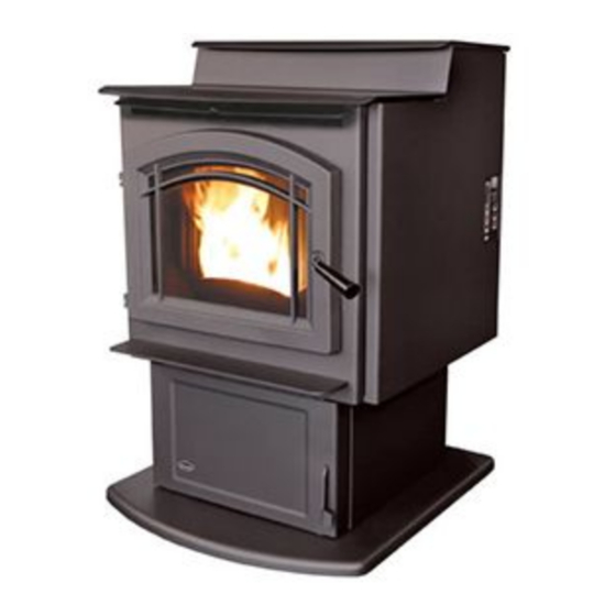
M55-FS-2
F R E E - S T A N D I N G P E L L E T S T O V E
OWNER'S MANUAL
PLEASE READ THIS ENTIRE MANUAL BEFORE INSTALLATION AND USE
OF THIS PELLET-BURNING ROOM HEATER. FAILURE TO FOLLOW THESE
INSTRUCTIONS COULD RESULT IN PROPERTY DAMAGE, BODILY INJURY
OR EVEN DEATH.
Contact your building or fire officials about restrictions
and installation inspection requirements in your area.
50-2061
Version Française: www.enviro.com/fr.html
C# 4001609
Advertisement
Table of Contents

Related Manuals for Enviro M55-FS-2


Summary of Contents for Enviro M55-FS-2
- Page 1 OF THIS PELLET-BURNING ROOM HEATER. FAILURE TO FOLLOW THESE INSTRUCTIONS COULD RESULT IN PROPERTY DAMAGE, BODILY INJURY OR EVEN DEATH. Contact your building or fire officials about restrictions and installation inspection requirements in your area. 50-2061 Version Française: www.enviro.com/fr.html C# 4001609...
-
Page 2: Table Of Contents
Table of Contents Introduction........................3 Rating Label Location........................3 Fuel Quality..........................3 Eficiency and Emissions...........................4 Safety Warnings & Recommendations......................5 Operating Instructions..........................7 Dimensions & Specifications......................7 Control Board Functions.......................8 Automatic Safety Features of Your Pellet Stove................8 Operating Your Pellet Stove......................8 Turning Your Pellet Stove Off......................10 Slider/Damper Set-Up........................10 Adjustable Auger Cover Set-Up....................11 Routine Cleaning and Maintenance......................12... -
Page 3: Introduction
Fuel quality is important, please read the following: Your Enviro pellet stove has been designed to burn ¼” (6mm) dia wood pellets and other organic fuels. DO NOT use this appliance as an incinerator. DO NOT use unsuitable and non recommended fuels, including liquid fuels as this will void any warranties stated in this manual. -
Page 4: Eficiency And Emissions
FFiciency Rates: This manual describes the installation and operation of the Enviro M55 pellet heater. This heater is U.S. ENVIRONMENTAL PROTECTION AGENCY Certified to comply with 2020 particulate emission standards. Under specific test conditions this heater has been shown to deliver heat at rates ranging from 38,437-7817 Btu/hr. -
Page 5: Safety Warnings & Recommendations
To prevent the possibility of a fire, ensure that the appliance is properly installed by adhering to the installation instructions. An Enviro dealer will be happy to assist you in obtaining information with regards to your local building codes and installation restrictions. - Page 6 If this power cord should become damaged, a replacement power cord must be purchased from the manufacturer or a qualified Enviro dealer. Be careful that the electrical cord is not trapped under the appliance and that it is clear of any hot surfaces or sharp edges. This unit’s maximum power requirement is 504 watts.
-
Page 7: Dimensions & Specifications
Specifications imensions " (619mm) " (450mm) 29" (736mm) 29" (736mm) 26" (664mm) " (601mm) " (928mm) " (619mm) Figure 1: Dimensions of M-55-FS. peciFications Input rating when using: Wood Pellets/Corn - 55,000BTU (16.1KW•hr) & Wheat/Barley - 53,000BTU (15.5KW•hr). Table 1: M-55-FS Specifications. Description Fuel type Residential Pellet Heater... -
Page 8: Operating Instructions
Operating Instructions ontRoL oaRd unctions 1. ON/OFF BUTTON: Used to turn the unit ON and OFF manually. 2. COMBUSTION AIR TRIM BUTTON: Increases or Decreases the Fan voltage by 2.5volts on all feed settings. When pressed all lights on Heat Level Indicator will come on except the one that is the set point. - Page 9 Operating Instructions peRating eLLet tove DO NOT OPERATE THE UNIT WITH THE DOOR OR ASH BOX OPEN. Keep hopper lid closed except during re-fuelling. CAUTION: When operating during adverse weather, such as high winds or freezing rain, if the unit exhibits dramatic changes in combustion stop using the unit immediately.
-
Page 10: Turning Your Pellet Stove Off
Operating Instructions previous MANUAL setting. If the thermostat contacts remain open, the stove automatically begins its shutdown routine. The stove will re-light when the thermostat contacts close again. uRning eLLet tove • MANUAL and HI / LOW mode: To turn the unit OFF, simply press the ON / OFF button. This will stop the feed of pellets. -
Page 11: Adjustable Auger Cover Set-Up
Operating Instructions SPECIAL NOTES: Fuel quality is a major factor in how the stove will operate. If the fuel has a high moisture content or ash content the fire will be less efficient and has a higher possibility of the fire building up and creating clinkers (hard ash build-up). djustabLe ugeR oveR... -
Page 12: Routine Cleaning And Maintenance
Routine Cleaning and Maintenance The following list of components should be inspected and maintained routinely to ensure that the appliance is operating at its optimum and giving you excellent heat value. The appliance, flue gas connector and the chimney flue require regular cleaning. Check them for blockage prior to re-lighting after a prolonged shut down period. - Page 13 Routine Cleaning and Maintenance Heat eXcHangeR tubes (Weekly) The exchanger tube scraper rod handle is located above the firebox door. Move the handle all the way in and out a few times (ONLY WHEN THE UNIT IS COLD) in order to clean away any fly ash that may have collected on the heat exchanger tubes.
- Page 14 Routine Cleaning and Maintenance EXHAUST PASSAGES (Biannually) 1. Open the firebox door by lifting the handle. 2. Remove the burn pot assembly and clean all the parts. 3. Lubricate all screws with penetrating oil. Firebox Baffle 4. Lift the baffle, remove the firebox liner, and lift Firebox Liner out the firebox lower.
-
Page 15: Installation Instructions
Installation eciding HeRe to ocate youR eLLet ppLiance 1. Do not install the stove in a bedroom or room where people sleep in. 2. Locate the stove in a large and open room that is centrally located in the house. This will optimize heat circulation. -
Page 16: Clearances To Combustibles
Installation LeaRances to ombustibLes These dimensions are minimum clearances but it is Back Wall recommended that you ensure sufficient room for servicing, routine cleaning and maintenance. 3" (7.6cm) Side wall to unit 12 inches (30.5 cm) 3" (7.6cm) Back wall to unit 3 inches (76 cm) 12"... -
Page 17: Vent Termination Requirements
Installation eRmination eQuiRements IT IS RECOMMENDED THAT YOUR PELLET STOVE BE INSTALLED BY AN AUTHORIZED DEALER/INSTALLER. Table 2: Use in conjunction with Figure 7 for allowable exterior vent termination locations. Letter Minimum Clearance Description 24 in (61 cm) Above grass, top of plants, wood, or any other combustible materials. 48 in (122 cm) Beside/below any door or window that may be opened. -
Page 18: Outside Fresh-Air Connection
Installation utside ResH onnection This Heater must have adequate air for proper combustion in the room that it is installed. A Fresh-air intake is strongly recommended for all installations. Failure to install intake air may result in improper combustion as well as the unit smoking during power failures. -
Page 19: Mobile Home Installation
Installation obiLe nstaLLation ● Secure the heater to the floor using the four (4) holes in the pedestal. ● Ensure the unit is electrically grounded to the chassis of your home (permanently). ● Do not install in a room people sleep in. ●... -
Page 20: Horizontal Exhaust Through Wall Installation
Installation oRizontaL XHaust HRougH nstaLLation Vent installation: install vent at clearances specified by the vent manufacturer. A chimney connector shall not pass through an attic or roof space, closet or similar concealed spaces, or a floor, or ceiling. Where passage through a wall or partition of combustible construction is desired, the installation must conform to CAN/CSA-B365 Installation Code for Solid-Fuel-Burning Appliances and Equipment and with all local regulations, including those referring to regional and national. - Page 21 Installation 8. The pipe must extend at least 12” (30 cm) away from the building. If necessary, bring another length of pipe to the outside of the home to connect to the first section. Do not forget to place high temperature silicone around the pipe that passes through the thimble if required by vent manufacturer.
-
Page 22: Recommended - Through Wall With Vertical Rise And Horizontal Termination Installation
Installation Recommended - t HRougH eRticaL ise and oRizontaL eRmination nstaLLation Termination cap 90°elbow Wall framing A 45° down elbow with a screen may be used in Vertical section of vent pipe place of the termination cap (or stainless steel Wall strap termination hood). -
Page 23: Outside Vertical Installation
Installation utside eRticaL nstaLLations To accomplish an outside vertical pipe installation, follow the “h ” orizontal xhauSt hrough nStallationS section and then finish it by performing the following (refer to Figure 16). 1. Install a tee with clean out on the outside of the house. 2. -
Page 24: Inside Vertical Installation
Installation nside eRticaL nstaLLations 1. Place the unit on the hearth pad if a hearth pad is to be used (or on solid material if installed on a carpeted surface) and space the unit in a manner so when the pellet vent is installed vertically, it will meet the minimum clearance from a combustible wall stated by the vent manufacturer. -
Page 25: Hearth Mount Installation
Installation eaRtH ount nstaLLation Damper Removed or Fastened Open Mantel Minimum (8") 200mm from top of stove Clean-out tee Min (6") 150mm Fresh-air intake should com from chimney. If holes already exist fresh-air intake Floor can be taken through back Protection of the fireplace or through the ash dump. -
Page 26: Top Vent Adaptor
Installation daptoR *In order to achieve the maximum rated efficiency of 78.2% HHV purchase of a top vent adapter kit is required. Use the sheet metal screws provided to attach the kit to the rear of the unit as shown. Please see kit instruction manual for more detailed installation instructions. -
Page 27: Troubleshooting
Troubleshooting DO NOT: ● Service the stove with wet hands. The stove is an electrical appliance, which may pose a shock hazard if handled improperly. Only qualified technicians should deal with possible internal electrical failures. ● Do not remove from the firebox any screws without penetrating oil lubrication. WHAT TO DO IF: 1. - Page 28 Troubleshooting • Exhaust Temperature Sensor failure. Bypass sensor located on Exhaust Blower, if stove now operates properly, the unit may require cleaning or a new sensor. Contact your local dealer for service. • Check the agitator to make sure it is turning properly 3.
- Page 29 Troubleshooting 8. Ignitor - the pellets will not light. • Check the line fuse to see if it has blown. NOTE: The ignitor should be bright orange in color. • Everything else in the stove operates but the ignitor will not light the pellets. •...
-
Page 30: Wiring Diagram
Wiring Diagram Black Brown 2µF Capacitor Black Exhaust Blue Combustion Temperature Brown Blower Blue Blue Sensor Black White 120V Ground Air Pump White Plug Green Ground Ignitor White Thermostat Ground 5 Amp White Agitator Blue/Yellow Black Motor White Auger Yellow Yellow Motor Purple... -
Page 31: Parts List
EC-001 ⅝” I.D. Auger Brass Bushings (Set of 2) 50-1806 Stainless Steel Cast Agitator with Coupler 50-1697 Convection Blower 80mm 50-2064 Enviro Gel Decal 50-322 Auger With Paddles 50-1161 Ignitor Coil Type - 400 Watt 50-2142 Auger Stops (Clear Rubber) - Page 32 Parts List Reference # Description Part # ¼” Spring Pin 50-1701 Agitator Bushing Left Side 50-1703 Lower Ash Pan Door Complete 50-2071 Glass Only 14.88” X 11.36” (378x289mm) 50-2056 Glass Retainer 50-2065 Burn Pot Scraper Tool 50-1254 Door And Ash Door Gasket Firm - 10ft (3.05m) 50-2058 Ash Pan...
-
Page 33: Parts Diagram - Components
Parts Diagram - Components... -
Page 34: Parts Diagram - Steel
Parts Diagram - Steel... -
Page 35: Notes
Exclusions conditions herein set forth, this product against defects in material and workmanship An expanded list of exclusions is available at www.enviro.com/help/warranty.html during the specified warranty period starting from the date of original purchase at retail. This warranty does not cover: In the event of a defect of material or workmanship during the specified warranty period, ... -
Page 36: Installation Data Sheet
SERIAL NUMBER:___________________________ _________________________________________ DATE OF PURCHASE: _____________ (dd/mm/yyyy) ADDRESS: DATE OF INSTALLATION:___________ (dd/mm/yyyy) _________________________________________ MAGNEHELIC AT INSTALL:___________________ _________________________________________ INSTALLER’S SIGNATURE: _________________________________________ _________________________________________ PHONE:___________________________________ MANUFACTURED BY: SHERWOOD INDUSTRIES LTD. 6782 OLDFIELD RD. SAANICHTON, BC, CANADA V8M 2A3 www.enviro.com Summer 2021 C-16287...
Need help?
Do you have a question about the M55-FS-2 and is the answer not in the manual?
Questions and answers