
Related Manuals for Eneo IPP-72A0023MIA


Summary of Contents for Eneo IPP-72A0023MIA
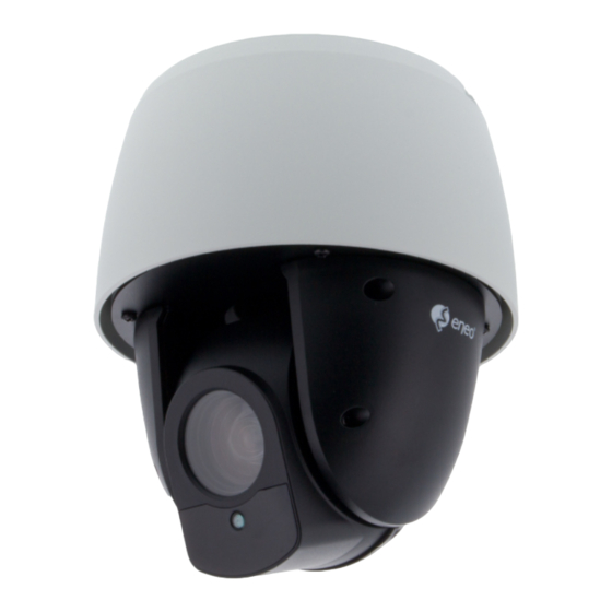
- Page 1 Quick Installation Guide 1/2.8” Network Dome, PTZ, Day&Night, 23x, H.265, WDR, 1920x1080, Infrared, IP66 IPP-72A0023MIA...
-
Page 2: Table Of Contents
Table of contents Components........................5 Installation ........................6 Mounting the Dome Camera ............................6 Locking the Dome Camera ............................7 Basic Configuration of Dome Camera System ......................8 Resetting to the factory default settings ........................9 Using the Reset button: .............................9 Connections ..................................10 Micro-SD Card Insertion ............................10 Connecting the Network ............................ - Page 3 Safety instructions General safety instructions • Before switching on and operating the system, first read this safety advice and the operating instructions. • Keep the operating instructions in a safe place for later use. • Installation, commissioning and maintenance of the system may only be carried out by authorised individuals and in accordance with the installation instructions - ensuring that all applicable standards and guidelines are followed.
- Page 4 Class A device note This is a Class A device. This device can cause malfunctions in the living area; in such an event, the operator may need to take appropriate measures to compensate for these. WEEE (Waste Electronical & Electronic Equipment) Correct Disposal of This Product (Applicable in the European Union and other European countries with separate collection systems).
-
Page 5: Components
Components This system comes with the following components; • Dome Camera • Installation Guide/CD • Template Sheet • Mounting Bracket • Safety Lanyard • Accessory Kit (4x Mounting screws (PH6 x 35.0), 4x Plastic anchors, 4x O-Rings) • Accessory Connector (3x 2-Pin Terminal Block, 2x 3-Pin Terminal Block) •... -
Page 6: Installation
Installation Mounting the Dome Camera The dome camera is for use in surface or pendent mounting applications, and the mounting member must be capable of supporting loads of up to 10 lb (4.5 kg). (Pendent mounting must use pendent mount accessory.) The dome cameras mounting bracket should be attached to a structural object, such as hard wood, wall stud or ceiling rafter that supports the weight of the dome camera. -
Page 7: Locking The Dome Camera
Locking the Dome Camera 1. Make screw holes on the ceiling using the supplied mounting Template Sheet (Figure A). 2. Fix the Mounting Bracket to the ceiling using supplied Anchors (4x) and Mounting Screws (4x) (Figure B). 3. Hook up the Safety Lanyard to the Safety Lanyard Hook of the Mounting Bracket (Figure C). 4. -
Page 8: Basic Configuration Of Dome Camera System
CAUTION 2: Before installing mounting bracket to surface pre-adjust the four mounting screws “A” on the base of the dome camera to best match the mounting bracket locked position. Unscrew the locking screw on the side of the dome’s base and fit the tab of the mounting bracket into the locking slot. -
Page 9: Resetting To The Factory Default Settings
Resetting to the factory default settings To reset the network camera to the original factory settings, go to the Setup > System > Maintenance web page (described in “System > Maintenance” of User Manual) or use the Reset button on the network camera, as described below: Micro-SD Card Slot Reset Button Using the Reset button:... -
Page 10: Connections
Connections Micro-SD Card Insertion User can install and change Micro-SD card as shown in the following picture. 1. Open the Micro-SD card cover. 2. Install or change Micro-SD card. 3. Close the Micro-SD card cover tightly to ensure waterproofing. Micro-SD Card Slot Reset Button Connecting the Network Connect a standard RJ-45 cable to the network port of the camera. -
Page 11: Connecting The Power
G (Ground) Notice: All the connectors marked G or GND are common. Connect the ground side of the alarm input and/or alarm output to the G (Ground) connector. AO (Alarm Output) The camera can activate external devices such as buzzers or lights. Connect the device to the AO (Alarm Output) and G (Ground) connectors. -
Page 12: Network Connection & Ip Assignment
The eneo Site Manager (downloadable from www.eneo-security.com) is used to locate all eneo network cameras in a local network. The tool does not need to be installed with a setup program. The program exe-file can be started with a simple double click to use the program. -
Page 13: Operation
Operation The network camera can be used with Windows operating system and browsers. The recommended browsers are Internet Explorer, Safari, Firefox, Opera and Google Chrome with Windows. Notice: To view streaming video in Microsoft Internet Explorer, set your browser to allow ActiveX controls. -
Page 14: Access From The Internet
Access from the internet Once connected, the network camera is accessible on your local network (LAN). To access the network camera from the Internet you must configure your broadband router to allow incoming data traffic to the network camera. To do this, enable the NAT traversal feature, which will attempt to automatically configure the router to allow access to the network camera. -
Page 15: Live View Page
Live View Page The Live View page comes in several screen modes: 1920x1080, 1280x1024, 1280x720(960), 1024x768, 704x480(576), 640x480(360) and 320x240. Users are allowed to select the most suitable one out of those modes. Adjust the mode in accordance with your PC specifications and monitoring purposes. General controls Live View Page Playback Page... -
Page 16: Video Streams
The Snapshot button takes a snapshot of the current image. The location where the image is saved can be specified. The Digital Zoom button activates a zoom-in or zoom-out function for video image on the live screen. The Full Screen button causes the video image to fill the entire screen area. No other windows will be visible. -
Page 17: Playback
Playback The Playback window contains a list of recordings made to the memory card. It shows each recording’s start time, length, the event type used to start the recording, calendar and time slice bar indicates if the recording is existed or not. The description of playback window follows. - Page 18 Forward Play: play forward the video clip. Fast forward play: play fast forward of the video clip. Go to the last: go to the end of the video clip. Clip copy: copy the video clip. Zoom In: zoom in the video clip. Full Screen: display full screen of the video.
-
Page 19: Network Camera Setup
⑧ Event List Window Event List displays the event(s) that were recorded in the SD local storage. Select a list and click the play button. The video clip will be played. Network Camera Setup This section describes how to configure the network camera. Administrator has unrestricted access to all the Setup tools, whereas Operators have access to the settings of Basic Configuration, which are Live View, Video &... - Page 20 Notice: If the password is lost, the network camera must be reset to the factory default settings. Please see ”Resetting to the Factory Default Setting”.
-
Page 21: Further Information
Further information Make sure to always upgrade to the latest firmware version available from the eneo web- site at www.eneo-security.com to receive the latest functionality for your product. The manual, and other software tools are available on the eneo website at www.eneo-security.com or on the included CD. - Page 22 Inhalt Komponenten ......................25 Installation ........................26 Befestigung der Dome-Kamera ..........................26 Dome-Kamera verriegeln ............................27 Basiskonfiguration des Dome-Kamera-Systems ....................28 Rücksetzen auf die Werkseinstellungen......................... 29 Verwendung der Rücksetztaste: .......................... 29 Anschlüsse ..................................30 Einführen einer MicroSD-Karte ..........................30 Anschluss an das Netzwerk ........................... 30 Audio anschließen ..............................
- Page 23 Sicherheitsanweisungen Sicherheitshinweise allgemein • Bevor Sie das System anschließen und in Betrieb nehmen, lesen Sie zuerst diese Sicherheitshinweise und die Betriebsanleitung. • Bewahren Sie die Betriebsanleitung sorgfältig zur späteren Verwendung auf. • Montage, Inbetriebnahme und Wartung des Systems darf nur durch dafür autorisierte Personen vorgenom- men und entsprechend den Installationsanweisungen - unter Beachtung aller mitgeltenden Normen und Richtlinien - durchgeführt werden.
- Page 24 • Bei abgedunkelter Umgebung und direktem Blick in den IR-Scheinwerfer ist ein Sicherheitsabstand von > 1 m zum Scheinwerfer einzuhalten. • Unsichtbare LED Strahlung nicht direkt mit optischen Instrumenten (z.B. Lupe, Vergrößerungsglas oder Mikroskop) betrachten, da sie eine Augengefährdung verursachen kann, LED Klasse 1M. •...
-
Page 25: Komponenten
Komponenten Das System wird mit den folgenden Komponenten geliefert: • Dome-Kamera • Installationsanleitung/CD • Bohrschablone • Montagehalterung • Sicherheitskabel • Montageset (4x Befestigungsschrauben (PH6 x 35,0), 4x Kunststoffdübel, 4x O-Ringe) • Steckverbindungen (3x 2-Pin Klemmleiste, 2x 3-Pin Klemmleiste) • RJ-45-Kupplung (wasserdicht) Hinweis: Adapter für 12V DC ist nicht im Lieferumfang enthalten. -
Page 26: Installation
Installation Befestigung der Dome-Kamera Die Dome-Kamera ist für den Einsatz in Anwendungen mit Aufbau- oder Abhängungs- montagen geeignet und das Befestigungselement muss Tragelasten bis 4,5 kg unterstüt- zen. (Für Abhängungsmontage wird Hängemontagezubehör benötigt). Die Montagehalterung der Dome-Kamera sollte an einem Bauelement, wie etwa Hartholz, einem Wandständer oder Deckenbalken, welches das Gewicht der Kamera trägt, befestigt werden. -
Page 27: Dome-Kamera Verriegeln
Dome-Kamera verriegeln 1. Bohren Sie die Löcher mit Hilfe der beiliegenden Schablone in die Decke (Abbildung A). 2. Befestigen Sie die Montagehalterung mit den beiliegenden Dübeln (4x) und Befestigungs- schrauben (4x) an der Decke (Abbildung B). 3. Hängen Sie das Sicherheitskabel an den Haken an der Montagehalterung (Abbildung C). 4. -
Page 28: Basiskonfiguration Des Dome-Kamera-Systems
ACHTUNG 2: Bevor Sie die Montagehalterung an der Oberfläche befestigen sollten Sie die Befestigungsschrauben "A" am Unterteil der Dome-Kamera vorjustieren damit Sie in der Verriegelungsposition optimal passen. Drehen Sie die Verriegelungsschraube an der Seite des Domeunterteils heraus und führen Sie die Lasche der Montagehalterung in den Verriegelungsschlitz. -
Page 29: Rücksetzen Auf Die Werkseinstellungen
Die Installation der Kamera darf nur von qualifiziertem Personal in Übereinstimmung mit den am Ort der Installation gültigen elektrischen und mechanischen Bestimmungen erfolgen. Rücksetzen auf die Werkseinstellungen Um die Netzwerkkamera auf die Werkseinstellungen zurückzusetzen, rufen Sie die Webseite Konfiguration > System > Wartung auf (beschrieben in der Betriebsanleitung unter „System >... -
Page 30: Anschlüsse
Anschlüsse Einführen einer MicroSD-Karte Sie können MicroSD-Karten wie in der folgenden Abbildung dargestellt einführen und wechseln. 1. Öffnen Sie die Abdeckung für den MicroSD-Kartenschlitz. 2. Führen Sie eine MicroSD-Karte ein oder wechseln Sie diese. 3. Schließen Sie die Abdeckung für den MicroSD-Kartenschlitz fest, um die Wasser- dichtigkeit sicherzustellen. -
Page 31: Anschließen Von Alarmen
Anschließen von Alarmen A1, A2, A3, A4 (Alarmeingang 1, 2, 3, 4) Sie können externe Geräte anschließen, die der Dome-Kamera externe Ereignisse sig- nalisieren, damit sie auf diese reagiert. Mechanische oder elektrische Schalter können zwischen die Anschlüsse A1,A2,A3,A4 (Alarmeingang 1,2,3,4) und G (Masse) geschaltet werden. -
Page 32: Netzwerkverbindung Und Ip-Zuweisung
Netzwerkverbindung und IP-Zuweisung Mit dem eneo Site Manager können alle eneo Netzwerk Kameras im lokalen Netzwerk erkannt werden (laden Sie die Software von www.eneo-security.com herunter). Das Tool muss nicht mit einem Setup Programm installiert werden. Die exe-Datei des Programms kann mit einem Doppelklick direkt gestartet und benutzt werden. -
Page 33: Bedienung
Bedienung Die Netzwerkkamera kann mit einem Windows-Betriebssystem und Browsern verwen- det werden. Die empfohlenen Browser sind Internet Explorer, Safari, Firefox, Opera und Google Chrome in Windows. Hinweis: Um das Video-Streaming mit dem Microsoft Internet Explorer zu ermögli- chen, müssen Sie Ihren Browser so einstellen, dass ActiveX Controls erlaubt werden. Zugriff über einen Browser 1. -
Page 34: Zugriff Über Internet
Zugriff über Internet Nach dem Anschluss ist die Netzwerkkamera in Ihrem lokalen Netzwerk (LAN) verfügbar. Um vom Internet aus auf die Netzwerkkamera zugreifen zu können, müssen Sie Ihren Breitband-Router so konfigurieren, dass eingehende Verbindungen zur Netzwerkkamera zugelassen werden. Schalten Sie dazu die Funktion "NAT-Traversal" ein, um den Router automatisch so zu konfigurieren, dass der Zugriff auf die Netzwerkkamera möglich ist. -
Page 35: Live View-Seite
Hinweis: HTTPS (Hypertext Transfer Protocol over SSL) ist ein Protokoll, das zur Ver- schlüsselung der zwischen Webbrowser und Servern ausgetauschten Daten verwendet wird. Das HTTPS-Zertifikat ist die Grundlage des verschlüsselten Datenaustauschs. Live View-Seite Die Live View-Seite kann in verschiedenen Anzeigemodi angezeigt werden: 1920 x 1080, 1280 x 1024, 1280 x 720 (960), 1024 x 768, 704 x 480 (576), 640 x 480 (360) und 320 x 240. -
Page 36: Video-Streams
Die Stopp-Schaltfläche beendet die Wiedergabe des Video-Streams. Durch das Anklicken wird zwischen Start und Stopp umgeschaltet. Durch Anklicken der Play-Schaltfläche wird die Verbindung zur Netzwerkkamera aufgebaut bzw. das Abspielen eines Video-Streams begonnen. Die Pause-Schaltfläche unterbricht die Wiedergabe des Video-Streams. Mit der Snapshot-Schaltfläche wird eine Kopie des aktuellen Bildes erstellt. Der Ort, an dem die Datei gespeichert wird, kann angegeben werden. -
Page 37: Wiedergabe
Die Live View-Seite der Netzwerkkamera bietet Zugriff auf H.264, H.265 und Motion JPEG Video-Streams und auf die Liste der verfügbaren Video-Streams. Andere Anwendungen und Clients können ebenfalls direkt auf diese Video-Streams/Bilder zugreifen, ohne die Live View-Seite aufrufen zu müssen. Wiedergabe Das Wiedergabe-Fenster enthält eine Liste der auf der Speicherkarte gespeicherten Auf- zeichnungen. - Page 38 Rückwärtswiedergabe: Rückwärtswiedergabe des Video-Clips. Schrittweise Rückwärtswiedergabe: Bildweise im Video-Clip zurückspulen. Pause: Wiedergabe des Video-Clips pausieren. Schrittweise Vorwärtswiedergabe: Bildweise im Video-Clip vorwärtsspulen. Vorwärtswiedergabe: Vorwärtswiedergabe des Video-Clips. Schnelle Vorwärtswiedergabe: Schnelle Vorwärtswiedergabe des Video-Clips. Zum Ende springen: Zum Ende des Video-Clips springen. Clip kopieren: Kopieren des Video-Clips. Ansicht vergrößern: Vergrößerte Darstellung des Video-Clips.
-
Page 39: Netzwerkkamera-Konfiguration
Wählen Sie eine Suchoption aus der Dropdown-Liste aus und klicken Sie dann auf die GO-Schaltfläche (Starten). Sie können auch einen Zeitraum für die Suche eingeben. Wenn Sie auf Startdatum oder Enddatum klicken, wird der Suchkalender angezeigt. ⑧ Ereignislistenfenster Die Ereignisliste zeigt die Ereignisse, die auf dem lokalen SD-Speicher aufgezeichnet wurden. - Page 40 Hinweis: Wenn das Kennwort verloren gegangen ist, muss die Netzwerkka- mera auf die Werkseinstellungen zurückgesetzt werden. Siehe „Rücksetzen auf die Werkseinstellungen“.
-
Page 41: Weitere Informationen
Die aktuellsten Firmware-Versionen finden Sie auf unserer Website unter www.eneo-security.com. Das Benutzerhandbuch und weitere Software-Tools sind auf der eneo Website unter www.eneo-security.com oder auf der mitgelieferten CD verfügbar. Informationen zu kompatiblen Video Management Software-Lösungen finden Sie in der Kategorie Videomanagement unter www.eneo-security.com. - Page 42 Contenu Composants .........................45 Installation ........................46 Montage de la caméra ..............................46 Caméra dôme verrouillable ........................... 47 Configuration de base du système de caméra dôme ..................48 Réinitialisation aux paramètres par défaut d'usine ................... 49 Utilisation du bouton Reset : ..........................49 Raccordements ................................
- Page 43 Instructions de sécurité Consignes de sécurité générales • Avant de brancher et de mettre en service le système, veuillez lire d'abord ces consignes de sécurité ainsi que la notice d'instructions. • Conservez soigneusement la notice d'instructions en vue d'une utilisation ultérieure. •...
- Page 44 • Une distance de sécurité > 1 m doit être respectée par rapport au projecteur dans un environnement sombre, quand on regarde directement dans le projecteur IR. • Les rayons invisibles des LED ne doivent pas être observés directement avec des instruments optiques (par ex.
-
Page 45: Composants
Composants Le système est fourni avec les composants suivants : • Caméra dôme • Guide d'installation / CD • Gabarit de montage • Support de montage • Courroie de sécurité • Kit d'accessoires (4x Vis de fixation (PH6 x 35.0), Chevilles en plastique (4x), 4x Joints toriques) •... -
Page 46: Installation
Installation Montage de la caméra Le dôme est fait pour un montage en saillie ou encastré, à condition que l´ensemble de montage puisse supporter une charge max. de 4,5 kg. (Pour un montage en saillie, utiliser absolument les accessoires de fixation livrés.) Les supports de fixation de la caméra dôme doivent être fixés à... -
Page 47: Caméra Dôme Verrouillable
Caméra dôme verrouillable 1. Percer les trous au plafond au moyen des gabarits de montage (Figure A). 2. Fixer les supports de fixation en utilisant les chevilles (4x) et les vis de montage (4x) (Figure 3. Fixer les courroies de sécurité aux ergots de verrouillage des supports de fixation (Figure C). 4. -
Page 48: Configuration De Base Du Système De Caméra Dôme
ATTENTION 2 : Avant d´installer les supports de fixation, pré-ajuster les quatre vis de fixation "A" à la base du dôme pour avoir une position de verrouillage optimale. Dévisser la vis de blocage sur le côté du dôme et insérer l´ergot de verrouillage dans la fente de verrouillage. -
Page 49: Réinitialisation Aux Paramètres Par Défaut D'usine
Réinitialisation aux paramètres par défaut d'usine Pour réinitialiser la caméra réseau aux paramètres d'usine, allez sur la page Internet Setup>System> Maintenance (voir le manuel de l'utilisateur « Système > Maintenance ») ou utilisez le bouton de réinitialisation sur la caméra réseau, comme décrit ci-dessous : Logement Carte microSD Bouton Reset (réinitialisation) Utilisation du bouton Reset :... -
Page 50: Raccordements
Raccordements Insérer la carte micro-SD L'utilisateur peut installer et changer la carte micro-SD comme le montre l'illustration suivante. 1. Ouvrir le couvercle du logement de la carte micro-SD. 2. Installer ou changer a carte micro-SD. 3. Bien refermer le couvercle du logement de la carte micro-SD afin de s'assurer que le logement est étanche. -
Page 51: Connexion Des Alarmes
Connexion des alarmes A1,A2,A3,A4 (entrée alarme 1,2,3,4) Vous pouvez utiliser des périphériques externes afin de demander à la caméra de réagir aux événements. Les interrupteurs mécaniques ou électriques peuvent être reliés aux connecteurs A1,A2,A3,A4 (Entrées d´alarme 1,2,3,4) et GND (Terre). G (Ground-Terre) Remarque : tous les connecteurs marqués G ou GND sont standard. -
Page 52: Connexion Au Réseau Et Attribution D'une Adresse Ip
Vous pouvez maintenant effectuer une réinitialisation d'usine de la caméra dans le ges- tionnaire de site eneo Site Manager. Pour plus d´informations, merci de vous référer au « eneo Site Manager Quick Start Guide » (guide de démarrage rapide du gestionnaire de site eneo). -
Page 53: Fonctionnement
Fonctionnement La caméra de réseau peut être utilisée avec un système d'exploitation Windows et la plupart des navigateurs standards. Les navigateurs recommandés sont Internet Explorer, Safari, Firefox, Opera et Google Chrome sous Windows. Remarque : pour consulter la vidéo en streaming dans Microsoft Internet Explorer, configurez votre navigateur de manière à... -
Page 54: Accès À Partir De L'internet
Accès à partir de l’internet Une fois connectée, la caméra réseau est accessible au sein de votre réseau local (LAN). Pour accéder à la caméra réseau depuis l'Internet, vous devez configurer votre routeur à large bande afin d’autoriser le trafic de données entrantes vers la caméra réseau. À cette fin, activez la fonction NAT-traversal, laquelle essaiera de configurer automatiquement le routeur pour permettre un accès à... -
Page 55: Page Live View (Affichage En Direct)
Remarque : Le protocole HTTPS (Hypertext Transfer Protocol over SSL) est utili- sé pour crypter le trafic entre les navigateurs Web et les serveurs. Le certificat HTTPS contrôle l'échange crypté d'informations. Page Live View (affichage en direct) La page Live View propose plusieurs modes écran : 1920x1080, 1280x1024, 1280x720(960), 1024x768, 704x480(576), 640x480(360) et 320x240. -
Page 56: Streaming Vidéo
Le bouton Stop arrête le flux vidéo en cours de lecture. Réappuyer sur la touche permet de basculer entre start et stop. Le bouton Play (lecture) établit une connexion à la caméra réseau ou lance la lecture d'un flux vidéo. Le bouton Pause marque une pause dans la lecture du flux vidéo. -
Page 57: Lecture
La page d'affichage en direct de la caméra réseau permet d’accéder aux flux vidéo H.264, H.265 et Motion JPEG, ainsi qu’à la liste des flux vidéo disponibles. D’autres applications et clients peuvent également accéder directement à ces flux/images vidéo via la page Live View. - Page 58 Retour : la séquence vidéo est lue en sens inverse. Reculer d'un pas : la séquence vidéo recule d'une trame. Pause : pause Lecture of the video clip. Avancer d'un pas : la séquence vidéo avance d'une trame. Lecture normale : la séquence vidéo est lue normalement. Avance rapide : la séquence vidéo est avancée rapidement.
-
Page 59: Configuration De La Caméra Réseau
Sélectionnez une option de recherche dans la liste déroulante et cliquez sur le bouton GO. Vous pouvez également saisir la période pour la recherche. Si vous cliquez sur une des zones Date de début ou Date de fin, le calendrier de la recherche s'affiche. ⑧... - Page 60 Remarque : en cas de perte du mot de passe, la caméra réseau doit être réinitialisée aux paramètres d'usine. Voir « Réinitialisation aux paramètres par défaut d'usine ».
-
Page 61: Complément D'information
Le manuel utilisateur et d’autres outils logiciels sont disponibles sur le site web eneo www.eneo-security.com ou sur le CD joint. Des informations concernant les solutions logicielles de gestion vidéo compatibles sont disponibles dans la catégorie Videomanagement (gestion des vidéos) sur www.eneo-se-... - Page 62 Indice Componenti .........................65 Installazione .........................66 Montaggio della telecamera ............................66 Bloccaggio della telecamera dome ........................67 Configurazione di base del sistema telecamera dome..................68 Ripristino delle impostazioni predefinite ......................69 Utilizzo del tasto Reset: ............................69 Collegamenti ..................................70 Inserimento della scheda micro SD ........................70 Collegamento alla rete ............................
- Page 63 Istruzioni per la sicurezza Istruzioni generali per la sicurezza • Prima di collegare e mettere in funzione il sistema, leggete le istruzioni per la sicurezza e le istruzioni per l'uso. • Conservate con cura le istruzioni per l'uso per un eventuale utilizzo futuro. •...
- Page 64 • Deve essere mantenuto un margine di sicurezza di > 1 m dal proiettore se si guarda direttamente nel proiettore IR in un ambiente buio. • Non guardare direttamente le radiazioni LED invisibili utilizzando strumenti ottici (ad es. lente, lente di ingrandimento o microscopio) per prevenire danni agli occhi ( LED classe 1M).
-
Page 65: Componenti
Componenti Il sistema viene fornito con i componenti seguenti: • Telecamera dome • Guida/CD di installazione • Dima • Staffa di montaggio • Cordino di sicurezza • Kit di accessori (4x viti di montaggio (PH6 x 35,0), 4x tasselli di plastica, 4x O-Ring) •... -
Page 66: Installazione
Installazione Montaggio della telecamera La telecamera dome è destinata all'uso in applicazioni con installazione a muro o a so- spensione; l'elemento di installazione deve essere in grado di sostenere carichi fino a 4,5 kg. (per l'installazione a sospensione deve essere utilizzato l'accessorio per il montaggio a sospensione). -
Page 67: Bloccaggio Della Telecamera Dome
Bloccaggio della telecamera dome 1. Fare i buchi per le viti sul soffitto utilizzando la dima fornita (figura A). 2. Fissare la staffa di montaggio al soffitto utilizzando i tasselli (4x) e le viti di montaggio (4x) in dotazione (figura B). 3. -
Page 68: Configurazione Di Base Del Sistema Telecamera Dome
ATTENZIONE 2: prima di installare la staffa di montaggio pre-regolare le quattro viti di montaggio "A" alla base della telecamera dome adattandole il più possibile alla posizione di bloccaggio della staffa. Svitare la vite di bloccaggio a lato della base della telecamera dome e inserire la linguetta della staffa di montaggio nella fessura di bloccaggio. -
Page 69: Ripristino Delle Impostazioni Predefinite
La telecamera deve essere installata da tecnici di assistenza qualificati in conformità a tutti i regolamenti locali e statali relativi all'elettricità e agli edifici. Ripristino delle impostazioni predefinite Per ripristinare le impostazioni predefinite della telecamera di rete, andare alla pagina web Setup (Impostazione)>System (Sistema)>... -
Page 70: Collegamenti
Collegamenti Inserimento della scheda micro SD L'utente può installare e sostituire la scheda micro SD come indicato nella figura seguente. 1. Aprire il coperchio della scheda micro SD. 2. Installare o sostituire la scheda micro SD. 3. Chiudere bene il coperchio della scheda micro SD per garantire la tenuta all'acqua. -
Page 71: Collegamento Degli Allarmi
Collegamento degli allarmi A1,A2,A3,A4 (ingressi allarme 1,2,3,4) Si possono utilizzare dispositivi esterni per segnalare alla telecamera di reagire agli eventi. È possibile collegare interruttori meccanici o elettrici ai connettori A1, A2, A3, A4 (ingressi allarme 1, 2, 3, 4) e G (massa). G (terra) Avviso: tutti i connettori marcati G o GND sono comuni. -
Page 72: Connessione Alla Rete E Assegnazione Dell'ip
Lo strumento eneo Site Manager (scaricabile da www.eneo-security.com) viene utilizzato per individuare tutte le telecamere di rete eneo in una rete locale. Non occorre installare lo strumento con un programma di installazione. È possibile avviare il file .exe del pro- gramma facendo doppio clic su di esso. -
Page 73: Funzionamento
Funzionamento La telecamera di rete può essere utilizzata con il sistema operativo e i browser Windows. I browser consigliati con Windows sono Internet Explorer, Safari, Firefox, Opera e Google Chrome. Avviso: per visualizzare un video in streaming in Microsoft Internet Explorer, attivare i controlli ActiveX nel browser. -
Page 74: Accesso Da Internet
Accesso da Internet Una volta collegata, la telecamera di rete è accessibile nella propria rete locale (LAN). Per accedere alla telecamera di rete da Internet occorre configurare il router a banda larga affinché consenta il traffico dati in entrata alla telecamera di rete. Per far ciò, attivare la funzione di attraversamento del NAT, che tenterà... -
Page 75: Pagina Live View
raffigurata sotto. Per impostare la password tramite una connessione HTTPS crittografata, vedere System (Sistema)> Security (SIcurezza)> HTTPS nel manuale utente. Avviso: HTTPS (Hypertext Transfer Protocol over SSL) è un protocollo utilizzato per crittografare il traffico tra browser web e server. Il certificato HTTPS controlla lo scambio crittografato delle informazioni. -
Page 76: Barra Degli Strumenti Di Controllo
Barra degli strumenti di controllo La barra degli strumenti del visualizzatore live è disponibile soltanto nella pagina del browser web. Mostra i pulsanti seguenti: Il pulsante Stop arresta lo stream video in fase di riproduzione. Premendo nuovamen- te il pulsante si cambia da Start a Stop e viceversa. Il pulsante Start effettua il collegamento alla telecamera di rete o avvia la riproduzione di uno stream video. -
Page 77: Stream Video
Stream video La telecamera di rete offre diversi formati di stream video e immagini. Il tipo utilizzato dipende dalle esigenze dell'utente e dalle proprietà della rete. La pagina Live View della telecamera di rete fornisce accesso a stream video H.264, H.265 e Motion JPEG, nonché... - Page 78 visualizzare una registrazione dalla memoria locale SD, selezionarla dall'elenco e fare clic sui pulsanti di riproduzione. Vai all'inizio: va all'inizio della videoclip. Riproduzione indietro veloce: riproduce rapidamente la videoclip. Riproduzione indietro: riproduce il videoclip all'indietro. Riproduzione indietro frame per frame: va indietro di un frame nel videoclip. Riproduzione indietro frame per frame: va indietro di un frame nel videoclip.
-
Page 79: Configurazione Della Telecamera Di Rete
e ora di riproduzioneMostra la data e l'ora della riproduzione del video. ⑦ Finestra di ricerca eventi Selezionare un'opzione di ricerca nell'elenco a discesa e fare clic sul pulsante GO (Vai). È anche possibile inserire l'intervallo di tempo per la ricerca. Facendo clic nell'area della data di inizio o della data di fine viene visualizzato il calendario di ricerca. - Page 80 Avviso: in caso di perdita della password è necessario resettare la telecamera di rete riportandola alle impostazioni predefinite. Vedere "Ripristino delle impostazioni predefinite".
-
Page 81: Altre Informazioni
Il software fornito con questo prodotto contiene software protetto da copyright il cui utilizzo viene concesso con licenze open source. È possibile richiedere a Eneo il codice sorgente completo per un periodo di tre anni dopo l'ultima spedizione di questo prodotto inviando un'e-mail a: opensource@eneo-security.com. - Page 84 VIDEOR E. Hartig GmbH Exclusive distribution through specialised trade channels only. VIDEOR E. Hartig GmbH Carl-Zeiss-Straße 8 63322 Rödermark/Germany Tel. +49 (0) 6074 / 888-0 Technical changes reserved Fax +49 (0) 6074 / 888-100 www.videor.com...
Need help?
Do you have a question about the IPP-72A0023MIA and is the answer not in the manual?
Questions and answers