
Related Manuals for Eneo IPP-82A0030MIA


Summary of Contents for Eneo IPP-82A0030MIA
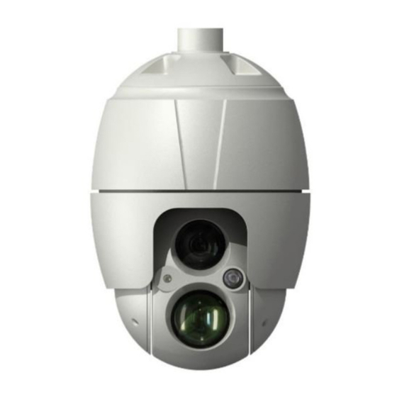
- Page 1 Quick Installation Guide 1/2,8” Network Dome, 2MP 1920x1080, PTZ, Day&Night, 4,3-129mm, Infrared, Outdoor IPP-82A0030MIA...
-
Page 2: Table Of Contents
Components........................5 Installation ........................6 Installation ...................................6 Installation - Wall Mount ............................6 Installation - Ceiling Mount ............................7 Basic Configuration of Camera System ........................9 Micro-SD Card Insertion .............................. 10 Connections ..................................10 Connecting the Network ............................10 Connecting Alarms ..............................11 Connecting the Power .............................11 Network Connection &... - Page 3 Safety instructions General safety instructions • Before switching on and operating the system, first read this safety advice and the operating instructions. • Keep the operating instructions in a safe place for later use. • Installation, commissioning and maintenance of the system may only be carried out by authorised individuals and in accordance with the installation instructions - ensuring that all applicable standards and guidelines are followed.
- Page 4 Class A device note This is a Class A device. This device can cause malfunctions in the living area; in such an event, the operator may need to take appropriate measures to compensate for these. WEEE (Waste Electronical & Electronic Equipment) Correct Disposal of This Product (Applicable in the European Union and other European countries with separate collection systems).
-
Page 5: Components
Components This system comes with the following components; • Dome Camera • Installation Guide/CD • RJ-45 Coupler • 2P screw type Connector • 5P screw type Connector • PoE Midspan • Install Adaptor... -
Page 6: Installation
Installation Installation You need one optional mount kit of the wall mount and the ceiling mount to install. The wall or ceiling mount must be attached to a structural object such as hard wood, concrete that will support the weight of the mount and dome camera. The use of a solid backboard is recommended when attaching to gypsum walls. -
Page 7: Installation - Ceiling Mount
Plastic Anchor (4x) Tapping Screw 8x35 (4x) Mounting Bracket (1x) Set Screw (1x) Adapter Set Screw (1x) Safety Wire Access Plate Srew Machine 3x5 (2x) Select a suitable mounting location and verify there is sufficient cable to reach the mid- dle of the Wall Mount. - Page 8 Seal using silicone rub- ber around the circle Plastic Anchor (3x) Ceiling Mount (1x) Set Screw (2x) Locking Nut (1x) Tapping Screw 6x35 (3x) Socket (1xI) Safety Wire (1x) Screw Machine M5x6 (1x) Pipe (1x) Socket Pipe PF 1.5 inch (1x) Set Screw (3x) Adapter PT 1.5 inch (1x) Set Screw (1x)
-
Page 9: Basic Configuration Of Camera System
1. Select a suitable mounting location and verify there is sufficient cable to connect with cables from the housing. 2. Mark and drill mounting holes in the surface using the ceiling mount bracket. 3. Pull out cables required to connect to the dome camera from the ceiling. 4. -
Page 10: Micro-Sd Card Insertion
The camera must be installed by qualified service personnel in accordance with all local and federal electrical and building codes. Micro-SD Card Insertion User can install and change Micro-SD card as shown in the following picture. 1. Open the Micro-SD card cover. 2. -
Page 11: Connecting Alarms
• Be careful not to reverse the polarity when you connect the power cable. Network Connection & IP assignment The eneo scanning device tool is used to locate all eneo network cameras in a local net- work. The tool does not need to be installed with a setup program. The program exe-file... - Page 12 After pushing the button „Find eneo devices“ you will get a list of cameras connected to the local network. Highlight your camera in the list and open a context menu with a click of the right mouse button. Select the „Editing the camera IP address“ option to open a window for setting the cam- eras IP properties.
-
Page 13: Operation
Operation The network camera can be used with Windows operating system and browsers. The recommended browsers are Internet Explorer, Safari, Firefox, Opera and Google Chrome with Windows. Notice: To view streaming video in Microsoft Internet Explorer, set your browser to allow ActiveX controls. -
Page 14: Access From The Internet
Access from the internet Once connected, the network camera is accessible on your local network (LAN). To access the network camera from the Internet you must configure your broadband router to allow incoming data traffic to the network camera. To do this, enable the NAT traversal feature, which will attempt to automatically configure the router to allow access to the network camera. -
Page 15: Live View Page
Live View Page The Live View page comes in several screen modes: 1920x1080, 1280x1024, 1280x720(960), 1024x768, 704x480(576), 640x480(360) and 320x240. Users are allowed to select the most suitable one out of those modes. Adjust the mode in accordance with your PC specifications and monitoring purposes. General controls Live View Page Playback Page... -
Page 16: Video Streams
The Digital Zoom button activates a zoom-in or zoom-out function for video image on the live screen. The Full Screen button causes the video image to fill the entire screen area. No other windows will be visible. Press the ’Esc’ button on the computer keyboard to cancel full screen view. -
Page 17: Playback
Playback The Playback window contains a list of recordings made to the memory card. It shows each recording’s start time, length, the event type used to start the recording, calendar and time slice bar indicates if the recording is existed or not. The description of playback window follows. - Page 18 Forward Play: play forward the video clip. Fast forward play: play fast forward of the video clip. Go to the last: go to the end of the video clip. Clip copy: copy the video clip. Zoom In: zoom in the video clip. Full Screen: display full screen of the video.
-
Page 19: Network Camera Setup
⑧ Event List Window Event List displays the event(s) that were recorded in the SD local storage. Select a list and click the play button. The video clip will be played. Network Camera Setup This section describes how to configure the network camera. Administrator has unrestricted access to all the Setup tools, whereas Operators have access to the settings of Basic Configuration, which are Live View, Video &... -
Page 20: Resetting To The Factory Default Settings
Notice: If the password is lost, the network camera must be reset to the factory default settings. Please see ”Resetting to the Factory Default Setting”. Resetting to the factory default settings To reset the network camera to the original factory settings, go to the Setup > System > Maintenance web page (described in ”System >... -
Page 21: Further Information
(Default IP 192.168.1.10) Further information Make sure to always upgrade to the latest firmware version available from the eneo web- site at www.eneo-security.com to receive the latest functionality for your product. The manual, and other software tools are available on the eneo website at www.eneo-se- curity.com or on the included CD. - Page 22 Komponenten ......................25 Installation ........................26 Installation ..................................26 Installation - Wandmontage ..........................26 Installation - Deckenmontage ..........................28 Basiskonfiguration des Kamera-Systems ....................... 30 Einführen einer MicroSD-Karte ..........................31 Anschlüsse ..................................32 Anschluss an das Netzwerk ........................... 32 Anschließen von Alarmen ............................32 Anschluss der Stromversorgung .........................
- Page 23 Sicherheitsanweisungen Sicherheitshinweise allgemein • Bevor Sie das System anschließen und in Betrieb nehmen, lesen Sie zuerst diese Sicherheitshinweise und die Betriebsanleitung. • Bewahren Sie die Betriebsanleitung sorgfältig zur späteren Verwendung auf. • Montage, Inbetriebnahme und Wartung des Systems darf nur durch dafür autorisierte Personen vorge- nommen und entsprechend den Installationsanweisungen - unter Beachtung aller mitgeltenden Normen und Richtlinien - durchgeführt werden.
- Page 24 • Bei abgedunkelter Umgebung und direktem Blick in den IR-Scheinwerfer ist ein Sicherheitsabstand von > 1 m zum Scheinwerfer einzuhalten. • Unsichtbare LED Strahlung nicht direkt mit optischen Instrumenten (z.B. Lupe, Vergrößerungsglas oder Mikroskop) betrachten, da sie eine Augengefährdung verursachen kann, LED Klasse 1M. •...
-
Page 25: Komponenten
Komponenten Das System wird mit den folgenden Komponenten geliefert: • Dome-Kamera • Installationsanleitung/CD • RJ-45-Kupplung • 2-Pin-Schraubstecker • 5-Pin-Schraubstecker • PoE Midspan • Installationsadapter... -
Page 26: Installation
Installation Installation Für die Installation benötigen Sie ein optionales Montagekit für die Wand- bzw. die Deckenmontage. Das Montagekit für die Wand- bzw. die Deckenmontage muss an einem festen Unter- grund wie Hartholz oder Beton angebracht werden, der das Gewicht des Montagekits sowie der Dome-Kamera tragen kann. - Page 27 Kunststoffdübel (4x) Selbstschneidende Schrauben 8 x 35 (4x) Montagehalterung (1x) Befestigungsschraube (1x) Adapter Befestigungsschraube (1x) Sicherheitsdraht Abdeckplatte Kopfschrauben 3 x 5 (2x) Wählen Sie einen geeigneten Anbringungsort und überprüfen Sie, ob genügend Kabel vorhanden ist, um die Mitte des Wandarms zu erreichen. 1.
-
Page 28: Installation - Deckenmontage
Installation - Deckenmontage Das Montagekit für die Deckenmontage muss an einem festen Untergrund wie Beton angebracht werden, der das Gewicht des Montagekits sowie der Dome-Kamera tragen kann. - Page 29 Abdichten mit Silikon- gummi am gesamten Kreisumfang Kunststoff dübel (3x) Deckenhalterung (1x) Befestigungsschrauben (2x) Befestigungsmutter (1x) Selbstschneidende Schrauben 6 x 35 (3x) Ring (1x) Sicherheitsdraht (1x) Kopfschraube M5x6 (1x) Rohr (1x) Rohrring PF 1,5 Zoll (1x) Befestigungsschrauben (3x) Adapter PT 1,5 Zoll (1x) Befestigungsschraube (1x) Startpunkt (lan- Sollpunkt (kurze...
-
Page 30: Basiskonfiguration Des Kamera-Systems
1. Wählen Sie einen geeigneten Anbringungsort und überprüfen Sie, ob genügend Kabel vorhanden ist, um die Kabel des Gehäuses zu erreichen. 2. Markieren Sie mithilfe des Deckenmontagearms die Befestigungslöcher an der Oberfläche und bohren Sie sie. 3. Ziehen Sie die erforderlichen Kabel aus der Decke, um die Dome-Kamera anzuschließen. -
Page 31: Einführen Einer Microsd-Karte
Alarmausgang 2-Pin-Kabel SCHWARZ Die Installation der Kamera darf nur von qualifiziertem Personal in Übereinstimmung mit den am Ort der Installation gültigen elektrischen und mechanischen Bestimmungen erfolgen. Einführen einer MicroSD-Karte Sie können MicroSD-Karten wie in der folgenden Abbildung dargestellt einführen und wechseln. -
Page 32: Anschlüsse
Anschlüsse Anschluss an das Netzwerk Schließen Sie ein Standard-RJ-45-Kabel an den Netzwerkanschluss der Kamera an. Zum Anschluss an einen PC wird im Allgemeinen ein Crossover-Kabel verwendet, während zum Anschluss an einen Hub ein direktes Kabel (Patch-Kabel) verwendet wird. Anschließen von Alarmen A1, A2, A3, A4 (Alarmeingang 1, 2, 3, 4) Sie können externe Geräte anschließen, die der Dome-Kamera externe Ereignisse sig- nalisieren, damit sie auf diese reagiert. -
Page 33: Netzwerkverbindung Und Ip-Zuweisung
Die exe-Datei des Programms kann mit einem Doppelklick direkt von der CD gestartet und benutzt werden. Nach dem Drücken des Buttons “eneo Geräte suchen” erhalten Sie eine Liste der mit dem lokalen Netzwerk verbundenen Kameras. Markieren Sie Ihre Kamera in der Liste und öffnen Sie ein Kontextmenü... -
Page 34: Bedienung
Bedienung Die Netzwerkkamera kann mit einem Windows-Betriebssystem und Browsern verwen- det werden. Die empfohlenen Browser sind Internet Explorer, Safari, Firefox, Opera und Google Chrome in Windows. Hinweis: Um das Video-Streaming mit dem Microsoft Internet Explorer zu ermögli- chen, müssen Sie Ihren Browser so einstellen, dass ActiveX Controls erlaubt werden. Zugriff über einen Browser 1. -
Page 35: Zugriff Über Internet
Zugriff über Internet Nach dem Anschluss ist die Netzwerkkamera in Ihrem lokalen Netzwerk (LAN) verfügbar. Um vom Internet aus auf die Netzwerkkamera zugreifen zu können, müssen Sie Ihren Breitband-Router so konfigurieren, dass eingehende Verbindungen zur Netzwerkkamera zugelassen werden. Schalten Sie dazu die Funktion "NAT-Traversal" ein, um den Router automatisch so zu konfigurieren, dass der Zugriff auf die Netzwerkkamera möglich ist. -
Page 36: Live View-Seite
HINWEIS: Der Standardname und das Standardkennwort des Administrators lauten "admin". Wenn das Kennwort verloren gegangen ist, muss die Netzwerkka- mera auf die Werkseinstellungen zurückgesetzt werden. Siehe „Rücksetzen auf die Werkseinstellungen“. Um beim Einstellen des Admin-Kennworts das Abhören der Netzwerkverbindung zu verhindern, kann dies über eine verschlüsselte HTTPS-Verbindung geschehen, wozu ein HTTPS-Zertifikat erforderlich ist (siehe unten den Hinweis). -
Page 37: Allgemeine Steuerelemente
Allgemeine Steuerelemente Live View-Seite Wiedergabe-Seite Konfigurationsseite Hilfeseite Mit der Video-Dropdown-Liste können Sie einen konfigurierten oder einen vorprogrammierten Video-Stream auf der Live View-Seite anzeigen. Die Stream-Profile werden unter Setup (Konfiguration) > Basic Configuration (Grundkonfiguration) > Video und Bild konfiguriert. Weitere Informationen finden Sie unter "Grundkonfiguration > Video und Bild"... -
Page 38: Video-Streams
Mit der Schaltfläche Manuelle Auslösung wird ein Popup-Fenster aufgerufen, mit dem das Ereignis manuell gestartet oder gestoppt werden kann. Mit der PTZ-Schaltfläche wird ein Popup-Fenster aufgerufen, mit dem eine PTZ-Kame- ra geschwenkt, geneigt und gezoomt werden kann. Mit der VCA-Schaltfläche können die VCA-Regeleinstellungen und erkannte Objekte ein- oder ausgeblendet werden. -
Page 39: Wiedergabe
Wiedergabe Das Wiedergabe-Fenster enthält eine Liste der auf der Speicherkarte gespeicherten Auf- zeichnungen. Von jeder Aufzeichnung wird die Startzeit, Länge und der zum Starten der Aufzeichnung verwendete Ereignistyp angegeben. Der Kalender und Zeitstrahl zeigt an, ob eine Aufzeichnung existiert oder nicht. Beschreibung des Wiedergabe-Fensters: ①... - Page 40 Schrittweise Vorwärtswiedergabe: Bildweise im Video-Clip vorwärtsspulen. Vorwärtswiedergabe: Vorwärtswiedergabe des Video-Clips. Schnelle Vorwärtswiedergabe: Schnelle Vorwärtswiedergabe des Video-Clips. Zum Ende springen: Zum Ende des Video-Clips springen. Clip kopieren: Kopieren des Video-Clips. Ansicht vergrößern: Vergrößerte Darstellung des Video-Clips. Vollbild: Zeigt das Video im Vollbildmodus an. ③...
-
Page 41: Netzwerkkamera-Konfiguration
⑧ Ereignislistenfenster Die Ereignisliste zeigt die Ereignisse, die auf dem lokalen SD-Speicher aufgezeichnet wurden. Treffen Sie Ihre Auswahl und klicken Sie dann auf die Wiedergabe-Schaltfläche. Der Video-Clip wird abgespielt. Netzwerkkamera-Konfiguration In diesem Abschnitt wird die Konfiguration der Netzwerkkamera beschrieben. Administratoren haben uneingeschränkten Zugriff auf alle Konfigurationswerkzeuge, während Benutzer nur Zugriff auf die Grundkonfiguration haben, nämlich auf die Seiten Live View, Video und Bild, Audio, Ereignis, Dome-Konfiguration und System. -
Page 42: Rücksetzen Auf Die Werkseinstellungen
Hinweis: Wenn das Kennwort verloren gegangen ist, muss die Netzwerkka- mera auf die Werkseinstellungen zurückgesetzt werden. Siehe „Rücksetzen auf die Werkseinstellungen“. Rücksetzen auf die Werkseinstellungen Um die Netzwerkkamera auf die Werkseinstellungen zurückzusetzen, rufen Sie die Web- seite Konfiguration > System > Wartung auf (beschrieben in der Betriebsanleitung unter “System >... - Page 43 Reset-Taste Schlitz für MicroSD-Karte • Verwendung der Rücksetztaste: Folgen Sie den nachstehenden Anweisungen, um die Netzwerkkamera mit der Rücksetz- taste auf die Werkseinstellungen zurückzusetzen. 1. Schalten Sie die Netzwerkkamera aus, indem Sie sie vom Netzteil trennen. 2. Öffnen Sie die Abdeckung für den MicroSD-Kartenschlitz. 3.
-
Page 44: Weitere Informationen
Die aktuellsten Firmware-Versionen finden Sie auf unserer Website unter www.eneo-security.com. Das Benutzerhandbuch und weitere Software-Tools sind auf der eneo Website unter www.eneo-security.com oder auf der mitgelieferten CD verfügbar. Informationen zu kompatiblen Video Management Software-Lösungen finden Sie in der... - Page 45 Composants .........................48 Installation ........................49 Installation ..................................49 Installation - Montage mural ..........................49 Installation - Montage au plafond ........................51 Configuration de base du système de la caméra ....................53 Insérer la carte micro-SD ............................. 54 Raccordements ................................54 Connexion au port réseau............................54 Connexion des alarmes ............................
- Page 46 Instructions de sécurité Consignes de sécurité générales • Avant de brancher et de mettre en service le système, veuillez lire d'abord ces consignes de sécurité ainsi que la notice d'instructions. • Conservez soigneusement la notice d'instructions en vue d'une utilisation ultérieure. •...
- Page 47 • Une distance de sécurité > 1 m doit être respectée par rapport au projecteur dans un environnement sombre, quand on regarde directement dans le projecteur IR. • Les rayons invisibles des LED ne doivent pas être observés directement avec des instruments optiques (par ex.
-
Page 48: Composants
Composants Le système est fourni avec les composants suivants : • Caméra dôme • Guide d'installation / CD • Coupleur RJ-45 • Connecteur vissé 2P • Connecteur vissé 5P • Midspan PoE • Installer l'adaptateur... -
Page 49: Installation
Installation Installation Vous avez besoin d’un kit de montage mural et au plafond pour l’installation. Le montage mural ou au plafond doit être fixé à une structure en bois dur ou en béton capable de supporter le poids du montage et de la caméra dôme. L’utilisation d’un panneau solide est recommandée en cas de fixation à... - Page 50 Chevilles en plastique (4x) Vis taraudeuses 8x35 (4x) Support de montage (1x) Vis d’arrêt (1x) Adaptateur Vis d’arrêt (1x) Câble de sécurité Plaque d’accès Vis d’assemblage 3x5 (2x) Sélectionnez un emplacement de montage adéquat et vérifiez qu’il y a suffisamment de câble pour atteindre le milieu du montage mural.
-
Page 51: Installation - Montage Au Plafond
Installation - Montage au plafond La plaque de montage au plafond doit être fixée à une structure comme une dalle de béton apte à supporter le poids du support et de la caméra dôme. - Page 52 Joint réalisé à l’aide de caoutchouc silicone autour du cercle Chevilles en plastique (3x) Montage au plafond (1x) Vis d’arrêt (2x) Contre-écrou (1x) Vis taraudeuses 6x35 (3x) Douille (1x) Câble de sécurité (1x) Vis d’assemblage M5x6 (1x) Tuyau (1x) Douille manchon PF 1,5 pouce (1x) Vis d’arrêt (3x) Adaptateur PT 1,5 pouce (1x) Vis d’arrêt (1x)
-
Page 53: Configuration De Base Du Système De La Caméra
1. Sélectionnez un emplacement de montage adéquat et vérifiez qu’il y a suffisam- ment de câble pour un branchement aux câbles du boîtier. 2. Marquez et forez les orifices de montage dans la surface à l’aide du support de montage au plafond. 3. -
Page 54: Insérer La Carte Micro-Sd
La caméra doit être installée par un personnel qualifié conformément à tous les codes de construction et électriques locaux et fédéraux. Insérer la carte micro-SD L'utilisateur peut installer et changer la carte micro-SD comme le montre l'illustration suivante. 1. Ouvrir le couvercle du logement de la carte micro-SD. 2. -
Page 55: Connexion Des Alarmes
• Veillez à ne pas inverser la polarité quand vous connectez le câble d'alimentation. Connexion au réseau et attribution d’une adresse IP L´outil de balayage d´eneo est utilisé pour localiser toutes les caméras réseau dans le réseau local. Un programme d´installation n´est pas nécessaire pour installer cet outil. Le... - Page 56 Après avoir appuyé sur le bouton "Find eneo devices" (trouver le dispositif eneo), vous pourrez prendre connaissance de la liste des caméras connectées au réseau local. Sélec- tionner votre caméra dans la liste et ouvrir le menu contextuel en cliquant avec le bouton droit de la souris.
-
Page 57: Fonctionnement
Fonctionnement La caméra de réseau peut être utilisée avec un système d'exploitation Windows et la plupart des navigateurs standards. Les navigateurs recommandés sont Internet Explorer, Safari, Firefox, Opera et Google Chrome sous Windows. Remarque : pour consulter la vidéo en streaming dans Microsoft Internet Explorer, configurez votre navigateur de manière à... -
Page 58: Accès À Partir De L'internet
Accès à partir de l’internet Une fois connectée, la caméra réseau est accessible au sein de votre réseau local (LAN). Pour accéder à la caméra réseau depuis l'Internet, vous devez configurer votre routeur à large bande afin d’autoriser le trafic de données entrantes vers la caméra réseau. À cette fin, activez la fonction NAT-traversal, laquelle essaiera de configurer automatiquement le routeur pour permettre un accès à... -
Page 59: Page Live View (Affichage En Direct)
Remarque : Le protocole HTTPS (Hypertext Transfer Protocol over SSL) est utili- sé pour crypter le trafic entre les navigateurs Web et les serveurs. Le certificat HTTPS contrôle l'échange crypté d'informations. Page Live View (affichage en direct) La page Live View propose plusieurs modes écran : 1920x1080, 1280x1024, 1280x720(960), 1024x768, 704x480(576), 640x480(360) et 320x240. -
Page 60: Streaming Vidéo
Le bouton Stop arrête le flux vidéo en cours de lecture. Réappuyer sur la touche permet de basculer entre start et stop. Le bouton Start lance une connexion à la caméra réseau ou la lecture d’un flux vidéo. Le bouton Pause marque une pause dans la lecture du flux vidéo. Le bouton >Snapshot prend un instantané... -
Page 61: Lecture
clients peuvent également accéder directement à ces flux/images vidéo via la page Live View. Lecture La fenêtre Lecture contient une liste d'enregistrements sur la carte mémoire. Elle montre pour chaque enregistrement l'heure de début, la longueur, le type d'événement à l'ori- gine de l'enregistrement, le calendrier et la barre de plage horaire indiquant si l'enregis- trement existe ou non. - Page 62 Reculer d'un pas : la séquence vidéo recule d'une trame. Pause : interrompt la lecture du clip vidéo. Avancer d'un pas : la séquence vidéo avance d'une trame. Lecture normale : la séquence vidéo est lue normalement. Avance rapide : la séquence vidéo est avancée rapidement. Aller à...
-
Page 63: Configuration De La Caméra Réseau
⑧ Event List Window La liste d'événement affiche les événements enregistrés dans le stockage SD local. Sélec- tionnez une liste et cliquez sur le bouton de lecture. La séquence vidéo sera lue. Configuration de la caméra réseau Cette section décrit la configuration de la caméra réseau. L'administrateur dispose d'un accès illimité... -
Page 64: Réinitialisation Aux Paramètres Par Défaut D'usine
Remarque : en cas de perte du mot de passe, la caméra réseau doit être réinitialisée aux paramètres d'usine. Voir « Réinitialisation aux paramètres par défaut d'usine ». Réinitialisation aux paramètres par défaut d'usine Pour réinitialiser la caméra réseau aux paramètres d'usine, suivez la page Internet Se- tup>System>... -
Page 65: Complément D'information
Le manuel utilisateur et d’autres outils logiciels sont disponibles sur le site web eneo www.eneo-security.com ou sur le CD joint. Des informations concernant les solutions logicielles de gestion vidéo compatibles sont disponibles dans la catégorie Videomanagement (gestion des vidéos) sur www.eneo-se-... - Page 68 VIDEOR E. Hartig GmbH Exclusive distribution through specialised trade channels only. VIDEOR E. Hartig GmbH Carl-Zeiss-Straße 8 63322 Rödermark/Germany Tel. +49 (0) 6074 / 888-0 Technical changes reserved Fax +49 (0) 6074 / 888-100 www.videor.com...
Need help?
Do you have a question about the IPP-82A0030MIA and is the answer not in the manual?
Questions and answers