
Related Manuals for Eneo IPB-75M3610M0A


Summary of Contents for Eneo IPB-75M3610M0A
-
Page 1: User Manual
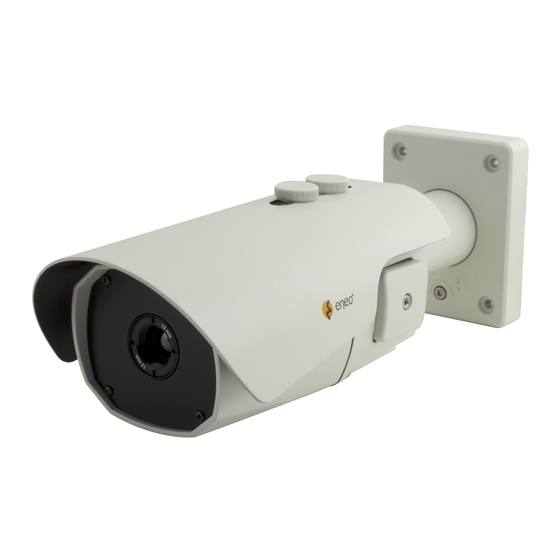
User Manual 1/1.8” Network Camera, 5MP, 2592x1944, Day&Night, D-WDR, 3.6-10mm, Infrared, Outdoor IPB-75M3610M0A... -
Page 2: Table Of Contents
Table of content Parts supplied .......................5 Part names ........................6 Installation instructions ....................7 Pan & Tilt adjustments ..............................8 Power supply connections .............................9 Quick Network Setup ....................11 Web viewer description .............................. 12 Player control & Display ............................12 PTZ Control .................................. 13 Setup Menu Table .............................. -
Page 3: Safety Instructions
Safety instructions General safety instructions • Before switching on and operating the system, first read this safety advice and the operating instructions. • Keep the operating instructions in a safe place for later use. • Installation, commissioning and maintenance of the system may only be carried out by authorised individuals and in accordance with the installation instructions - ensuring that all applicable standards and guidelines are followed. - Page 4 Class A device note This is a Class A device. This device can cause malfunctions in the living area; in such an event, the operator may need to take appropriate measures to compensate for these. WEEE (Waste Electronical & Electronic Equipment) Correct Disposal of This Product (Applicable in the European Union and other European countries with separate collection systems).
-
Page 5: Parts Supplied
Parts supplied • Network Camera • Operating Instruction • CD • Mounting Template • Cable Signal Sticker • Plastic Anchor: 6 x 30mm (4x) • Mounting Screw: 4 x 30mm (4x) • Assembly Screw: 4 x 15mm (4x) • Torque Wrench: 3mm (1x) •... -
Page 6: Part Names
Part names Sunshield bolt Sunshield Ethernet & Power cable Dual window Bracket Easy bracket Front case Rear case Lock/Unlock screw Micro SD Card slot Reset button LED Control switchl... -
Page 7: Installation Instructions
Installation instructions CAUTION: The camera’s base should be attached to a structural object, such as concrete, hard wood, wall stud or ceiling rafter that supports the weight of the camera. If necessary use appro- priate mounting material (e.g. anchors) instead of the material enclosed with the camera. -
Page 8: Pan & Tilt Adjustments
CAUTION: Extreme care should be taken NOT to scratch the window in front of lens. Care should be taken the cable is NOT to be damaged, kinked or exposed in the hazardous area. Do not expose the camera directly to a strong light source such as the sun or spot light. -
Page 9: Power Supply Connections
3. Inclination limit (Horizontal image alignment): Inclination limited to +/-90° max. ±90° Lock / Unlock screw Torque wrench Power supply connections Make sure the power is removed before the installation. Camera can work with either 24VAC or 12VDC, dual voltage power and PoE (IEEE Std. 802.3af ). Primary and secondary grounds are completely isolated to avoid the possible ground loop problems. - Page 10 AC24V/DC12V (Red wire) AC24V/GND (Black wire) Alarm-IN (Green wire) Alarm-OUT (Blue wire) GND (Gray wire) Audio-IN (Brown wire) GND (Gray wire) Audio-OUT (Orange wire) Attach the Signal Assignment Sticker in a visible spot for wiring reference.
-
Page 11: Quick Network Setup
IP addresses. The network camera‘s default IP address is: 192.168.1.10. 4. Right clicking the device name in the eneo Scan Device tool will bring up the context menu. Use the ‘Open Device Web Site’ option to access the camera. -
Page 12: Web Viewer Description
Web viewer description (A) Menu button : Click the button to show or hide the setup menu bar. (B) Model name : Show a camera model name connected. (C) Select Language : Set the web viewer language English, Deutsch or French. (D) Main setup menu bar : Set the camera or network functions. -
Page 13: Ptz Control
(4) Microphone: Enable or Disable the microphone. (5) Record: Record the current video on display. (6) Window Fit: Display live view to fit the window size. (7) Full Screen: Expand the current windows into maximum monitor size. Clicking ESC button or right button on mouse to back to the normal view. (8) Custom: Move the control bar to make preferred window size. -
Page 14: Setup Menu Table
Setup Menu Table Category Menu Player Control Pause, Snapshot, Speaker, Microphone, Record Display (Window Fit, Full Screen, Custom) LIVE VIEW Video Stream Stream1, Stream2, Stream3 Protocol HTTP, TCP, UDP PTZ Contol Zoom, Focus, Push AF PLAYBACK Event Search, Timeline Search, Timeline Bar Information General, Open source Information Source... - Page 15 Compression, Sample rate, Bitrate, Input Volume, Output Audio Volume Overwrite when storage is full, Record Continuous record setting Record Schedule Storage Format, Remove, Storage Information Motion, Tamper, Alarm In, System, Manual, Network Triggers Event Actions Record, Alarm Out, E-Mail, FTP, Video Boost SETUP Rules Event Processing, ONVIF Mapping...
-
Page 16: Quick Setup
Quick Setup Information The Information shows the camera basic information such as Model name, MAC address, IP address, Zeroconf IP address and Firmware version. Users User accounts can be added or modified or removed. The authority depends upon user group automatically and shows the permission status to access the menus. •... -
Page 17: Add
Click the Add, Edit, or Delete button for managing user account. To add a new user: 1. Click the Add tab, and type a new user name. (1 to 14 alphanumeric characters). User names are not case sensitive. 2. Type a password and retype confirm password. (1 to 8 alphanumeric characters). Passwords are case sensitive. -
Page 18: Date & Time
3. Click the OK button. The user profile is removed from the User List profile. Date & Time Current Time Shows the current date and time. New Time Select one of the server time. • Synchronize with computer time: Sets the time according to the clock on your computer. -
Page 19: Network
Network The DHCP (Dynamic Host Configuration Protocol) server has a feature that automatically assigns an IP address to the device if there is a device on the network. - Page 20 Obtain IP address via DHCP : Select the choice box if you want to assign the IP address from DHCP server automatical- ly, and then the remaining setting are read-only text. Use the following IP address: Select the choice box if you want to assign the IP address manually. IP address: The address of the camera connected to the network.
-
Page 21: Further Information
Further information Make sure to always upgrade to the latest firmware version available from the eneo web- site at www.eneo-security.com to receive the latest functionality for your product. The manual, and other software tools are available on the eneo website at www.eneo-se- curity.com or on the included CD. -
Page 22: General Description
General Description • 5.04Mega Pixel, NETWORK CAMERA, 2592x1944(15p/12.5p) • ONVIF Conformance • Zero configuration • Cross Web Browsing (IE, Edge, Safari, Firefox, Chrome) • Adaptive web resizing depending on layout & resolution of display device by RESPONSIVE WEB • Increased usability for all PC, tablet and mobile •... -
Page 23: Speci Cations
Speci cations ITEM IPB-75M3610M0A Imaging Sensor 1/1.8" Sony 5.04Mega pixel RGB Bayer Array CMOS Sensor Effective Pixels 2592(H) x 1944(V) approx. 5Mega pixels Sensitivity Color Mode: 0.07 lux (LED off), B/W Mode: 0.005 lux (LED off) Scanning mode Progressive Scan... - Page 24 Speci cations Security Multi User Authority, IP Filtering, HTTPS Network Time Sync. Synchronize Computer/NTP Server, Manual Software Reset Restart, Reset, Factory Default Auto Recovery Backup, Restore Remote Upgrade Using Web Browser Protocol TCP/IP, UDP, IPv4/v6, HTTP, HTTPS, FTP, UPnP, RTP, RTSP, RTCP, DHCP, ARP, Zeroconf, Bonjour Client Software Built-In Web, ONVIF Compatible 3rd Party VMS...
-
Page 25: Full Setup
Full Menu Setup 1. LIVE VIEW Enter the live view menu on the Web Viewer. ■ Player Control Pause: Freeze the current video. Snapshot: Take a picture of the video image currently on display. Supports the origin image size view, print, and save feature. Volume: Set the audio volume. -
Page 26: Playback
Full Menu Setup Zoom: Adjusts camera image zoom in/out ratio manually. Focus: Adjusts camera image focus manually. Push AF: When Push AF command is sent, camera becomes Auto Focus mode to adjust focus position for a while. 2. PLAYBACK Enter the playback menu on the Web Viewer. HTML5 blayback is supported. 0:00:00 ■... -
Page 27: Setup
Full Menu Setup 3. SETUP Enter the setup menu on the Web Viewer. 3-1. Information Refer to the menu ‘Quick Setup > Information’. 3-2. Video & Image 3-2-1. Source Specify the system performance. Depending on video source mode, each stream configuration will be affected and the streaming will be adjusted under system performance automatically. - Page 28 Full Menu Setup > Compression: Selects the stream profile that is to be used for transmissions. > Resolution: Specified as the number of pixel-columns (width) by the number of pixel-rows (height). It can be adjusted in the range from 320x240 to 1920x1080(2Mega pixel) / 2048x1536(3Mega pixel) / 2592x1944(5Mega pixel).
- Page 29 Full Menu Setup > Bitrate control: The bit rate can be set as CVBR (Constrained Variable Bit Rate) or CBR (Constant Bit Rate). > Bitrate: Indicates the quality of the video stream (rendered in kbps). The higher value means the higher video quality and bandwidth required. Stream3 ●...
- Page 30 Full Menu Setup 3-2-3. Image The image appearance allows you to adjust the camera setting parameters and change the camera orientation. All of parameters are recommended to be modifying for good image quality suitable for installation place. * NOTICE : After the setting click the SAVE button to apply the viewer.
- Page 31 Full Menu Setup > Saturation: Controls the saturation of detail in a scene. (1~18) > Hue: Controls the hue of detail in a scene. (1~7) > Sharpness: Controls the sharpness of detail in a scene. (1~8) > Enable flip image: Rotate the camera image 180 degrees vertically. >...
- Page 32 Full Menu Setup VerticalView > Min. Shutter: Adjust the Min. Shutter speed in the range 1/25(30)~1/10,000 sec. It is inactivated to set to ‘Automatic’ in Mode. > Shutter: Used to for controlling the gain while keeping the shutter time fixed to adjust the luminance.
- Page 33 Full Menu Setup VerticalView > Mode: Configure the options for White Balance. Select one of ATW-Indoor/ Outdoor, Shade, Clear sky, Fluorescent light, Light bulb, Flames, Manual options according to light conditions. The default setting is ATW-Indoor. > Cb Gain: Adjusts the picture output in the blue range. The White balance B gain can be adjusted in the range 10~255, where a higher value produces a higher blue image.
- Page 34 Full Menu Setup > Lens Calibration: It is necessary during the installation and when focus become out of control by the shock or vibration. > Enable Day & Night syncfocus: Enable only set to Manual mode. It is used to compensate the focusing automatically when the screen is out of focus by COLOR or BW switching.
- Page 35 Full Menu Setup ● > WDR: WDR is extended the gain range of the screen that is mostly useful if camera takes a simultaneous picture of both indoor and outdoor nearby window. It improves contrast of the picture in outdoor scenery as well as indoor. Video outputs image processed from two images by dual shutter (long and short shutter) in a field to provide the best dynamic range.
- Page 36 Full Menu Setup > BLC: Improves the visibility for the dark object by the bright backlight. Outside area of BLC window can over saturate. Set the Mode On/Off and Level to enable the backlight compensation function. > HLC: Cuts out the highlight area with black mask and excludes it from compensation. Set the Mode On/Off to enable the highlight compensation function.
- Page 37 Full Menu Setup VerticalView VerticalView ● The VerticalView allows you to get a vertically oriented video stream from the camera. The video is adapted perfectly to the monitored area, maximizing image quality while eliminating bandwidth and storage waste. The VerticalView is even more useful for modern HDTV network cameras that deliver a 16:9 aspect ratio since the resulting image will have a 9:16 aspect ratio - just the right thing for narrow corridors, hallways or aisles.
-
Page 38: Privacy Mask
Full Menu Setup 3-2-4. Privacy Mask A privacy mask is an area of solid color that prohibits users from viewing parts of the monitored area. The Privacy Mask List shows all the masks that are currently configured in this product and indicates if they are enabled. You can add a new mask, re-size the mask with the mouse, and give the mask a name. -
Page 39: Audio
Full Menu Setup 3-3. Audio: Check the Enable box to enable audio. Configure the basic audio settings for the camera. It supports the audio full duplex that can be transmits and receives audio in both directions at a time. ● Compression: G.711 is the international standard for encoding wired-telephone audio on 64kBit/s channel. -
Page 40: Record
Full Menu Setup 3-4. Record 3-4-1. Record Video can be recorded in the micro SD memory. Click the checkbox to overwrite the storage device or Reoord related setting to enable. ● Continuous Record Setting: > Video stream: Set the recording stream source. 3-4-2. - Page 41 Full Menu Setup 3-4-3. Storage Manage the storage device to be recorded and Show the current storage(SD card) information. ● Format: Click the Format button to format SD card. ● Remove: Remove or eject the storage device safely. [ NOTE ] Common Internet File System (CIFS) is a remote file access protocol that forms the basis for Windows file sharing, network printing, and various other network services.
-
Page 42: Event
Full Menu Setup 3-5. Event 3-5-1. Triggers Motion : ● Motion detection is used to generate an alarm whenever movement occurs (or stops) in the viewer. Up to 8 Motion and/or Mask windows can be created and configured. Once motion detection windows are configured, this camera can be configured to perform actions when motion is detected. - Page 43 Full Menu Setup To create a motion or mask window, follow steps: 1. Click the right button of mouse to see the mouse menu. 2. Select New Motion (or Mask) Window in the mouse menu. 3. Click and drag mouse to designate a motion area. - Include Type: define areas where motion should be detected.
- Page 44 Full Menu Setup > Dwell time: Setting duration time 1~180 sec. for the alarm output signal hold on as an input signaling source. Network : ● Used to trigger the event every time the network connection fails. Click the checkbox to activate the Network Loss event. >...
-
Page 45: Alarm Out
Full Menu Setup 3-5-2. Actions Record : ● Setting for the video stream, Recording time, Pre-recording time > Video stream: Set the recording stream source. > Recording time: Set the post-event recording time > Pre recording time: Set the pre-event recording time Alarm Out : ●... - Page 46 Full Menu Setup [ NOTE ] If a host name is used, a valid DNS server must be specified in the Network-Basic settings. > Port: Enter the SMTP server port number for the SMTP Server. The Port number can be adjusted in the range 1-65535. The default setting is 25. [ NOTE ] If your mail server requires authentication, click the Use (SMTP) authentication checkbox for use authentication to log in to this server.
- Page 47 Full Menu Setup 1) Receiver List: Enter the recipient’s email address as the receivers. > Receiver1~8: Enter the recipient’s email address as the receiver to test. 2) E-Mail (SMTP) Test: Enter the recipient's email address and click the Test button to test that the mail servers are functioning and that the email address is valid.
- Page 48 Full Menu Setup > User Name: Enter the User name as provided by your network administrator. - Anonymous login: Click the Anonymous login checkbox to permit anyone to access FTP server. > Password: Enter the Password as provided by your network administrator. [ NOTE ] If you permit to login FTP server by anyone without password, click the Anonymous login checkbox.
- Page 49 Full Menu Setup Video Boost: ● Setting for video framerate, bitrate, and quality when the event is occured. [ NOTE ] Video boost does not work during SD recording. 3-5-3. Rules This page shows current configuration status when event is activated. The common event actions will upload images to a specified destination or send an email or active an output port Event Processing :...
- Page 50 Full Menu Setup > Name: Shows the descriptive name provided by the user. > Trigger: Shows the source of event type as Alarm-In-1, Manual(4), Motion(1), Network and Tamper configured by the user. > Action: Shows the destination of event output as E-mail, FTP server, Video Boost Alarm-out port, Video boost and SD record.
- Page 51 Full Menu Setup > Name: Click in the Name box and type a user favorite event name. (1 to 31 alphanumeric characters). Event Trigger : Shows the Event source type to be configured. > Type: Selects the Event source type. Event Action : The Event Out provides that the camera will perform certain actions.
-
Page 52: System
Full Menu Setup 3-6. System 3-6-1. Security Users ● Refer to the menu ‘Quick Setup > Users’. HTTPS ● Provides the connection policy when user access to the camera using web browser. The default setting is HTTP&HTTPS. > HTTP: The sensitive data will be transfer without encrypted during transmission. Supports a URL that only starts with "HTTP: "... - Page 53 Full Menu Setup IP Filter ● Provides the IP filtering elements such as On/Off, Priority, Policy and IP Ranges. The default setting is disabling. > Enable IP filtering: Click the Enable IP filtering checkbox to enable the IP address filtering function. This dialog allows you to add new allowed/denied IP addresses.
- Page 54 Full Menu Setup 3-6-2. Date & Time Refer to the menu ‘Quick Setup > Date & Time’. 3-6-3. Network TCP/IP ● 1) IPv4 Address: The DHCP (Dynamic Host Configuration Protocol) server has a feature that automatically assigns an IP address to the device if there is a device on the network.
- Page 55 Full Menu Setup 2) IPv6 Address: Check this box to enable IPv6 address configuration. Other settings for IPv6 are configured in the network router. 3) DNS: DNS (Domain Name Service) provides the translation of host names to IP addresses on your network. >...
- Page 56 Full Menu Setup 4) Hostname: This camera can be accessed using a host name instead of an IP address. The host name is usually the same as the assigned DNS name. 5) Port: Allows the user to access the camera using web browser encrypted communication. >...
- Page 57 Full Menu Setup > Enable DDNS: Click the Enable DDNS checkbox to active DDNS service. > DDNS server: Enter the DDNS server name. The default DDNS server is security-device.name > Registered host: Enter the registered host name. > User name: Enter the registered user name to be used for accessing the DDNS server.
- Page 58 Full Menu Setup UPnP ● UPnP is enabled by default, and the network camera then is automatically detected by operating systems and clients that support this protocol. Click the Enable UPnP checkbox to disable the UPnP. Default setting is enabling.
- Page 59 Full Menu Setup > Friendly name: Click in the Friendly name box and type a description for the text you are creating (1 to 32 alphanumeric characters). If your computer is also enabled, the camera is automatically detected and a new icon is added to “Model Name-MAC address”. [ NOTE ] UPnP must also be enabled on your Windows computer.
- Page 60 Full Menu Setup 3-6-5. Maintenance 1) Maintain: Provides software reset of the camera when troubleshooting. > Restart: The camera is restarted without changing any of the setting. Use this method if the unit is not behaving as expected. > Reset: The unit is restarted and most current settings are reset to factory default values, but the following settings does not reset.
- Page 61 Full Menu Setup 3-6-6. Logs & Report The log files records event in the unit since the last system restart and can be a useful diagnostic tool when troubleshooting. The Report contains important information about the system. > System Log: Provides the system log information. >...
-
Page 62: Troubleshooting
Troubleshooting If you suspect a problem is being caused by incorrect configuration or some other minor problem, consult the troubleshooting guide below. Upgrading the Firmware Firmware is software that determines the functionality of the network camera. One of your first actions when troubleshooting a problem should be to check the current firmware. - Page 63 Troubleshooting Poor image quality. Increased lighting can often improve image quality. Check that there is sufficient lighting at the monitored location. Check all image and lighting settings. Rolling dark bands or flickering Try adjusting the Exposure Control setting under AE in image.
- Page 64 VIDEOR E. Hartig GmbH Exclusive distribution through specialised trade channels only. VIDEOR E. Hartig GmbH Carl-Zeiss-Straße 8 63322 Rödermark/Germany Tel. +49 (0) 6074 / 888-0 Technical changes reserved Fax +49 (0) 6074 / 888-100 www.videor.com...
Need help?
Do you have a question about the IPB-75M3610M0A and is the answer not in the manual?
Questions and answers