
Related Manuals for Haglof Vertex Laser Geo


Summary of Contents for Haglof Vertex Laser Geo
- Page 1 Vertex Laser Geo and Laser Geo User Guide ENGLISH 2021-02-02 VERTEX LASER GEO/ LASER GEO USER GUIDE 3.2 Vertex Laser Geo Laser Geo LASER AND ULTRASOUND LASER User Guide – English ©Haglöf Sweden...
-
Page 2: Table Of Contents
Vertex Laser Geo and Laser Geo User Guide ENGLISH 2021-02-02 HEIGHT DME – 2-POINT MEASURING WITH MANUAL CONTENTS DISTANCE ............... 19 OVERVIEW ................ 4 MAP TRAIL ..............20 ® ..............4 AGLÖF WEDEN ..........21 ISTANCE WITH ASER VERTEX LASER GEO LASER GEO ........ - Page 3 Vertex Laser Geo and Laser Geo User Guide ENGLISH 2021-02-02 Turn on the GPS............42 USE AS EXTERNAL GPS .......... 43 GPS fix ................ 43 Store a Single Coordinate ........... 44 ..........45 PS TO MEASURE AREA GPS DATA ..............45 EXAMPLES OF GOOGLE EARTH FILE, (KML FILE) .....
-
Page 4: Overview
3D measurements. Results are presented in an integrated heads-up display and on a large external graphic LCD display. The VERTEX LASER GEO model includes built-in, proven reliable ultrasonic distance technology, optimized for measurements in dense forest and for circular sample plot work. - Page 5 FORESTRY The VERTEX LASER GEO model is especially suitable for forestry measurement applications. The use of an ultrasonic transponder helps you to quickly and accurately determine if a tree is in or out a circular sample plot. The ultrasound method is superior compared to alternative methods, as it can be used in dense forests and areas with thick understory.
-
Page 6: Instrument Overview
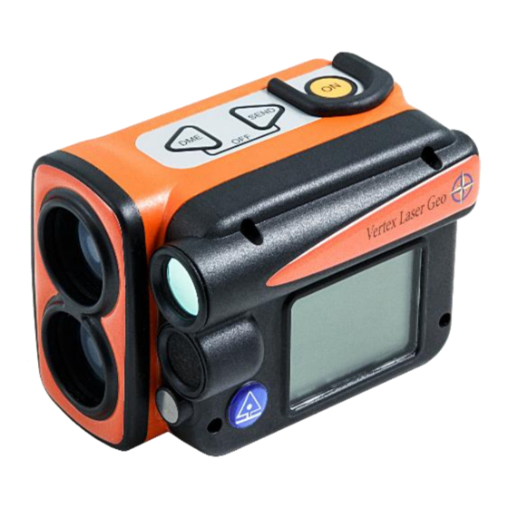
Vertex Laser Geo and Laser Geo User Guide ENGLISH 2021-02-02 INSTRUMENT OVERVIEW Buttons Laser optics Lens for Sight and Heads up display LCD display Ultrasound transreceiver (VERTEX LASER GEO) Ultrasound temperature sensor (VERTEX LASER GEO) Bluetooth transreceiver Rechargable Li-Ion battery GPS receiver 10. -
Page 7: Transponder T3
2021-02-02 TRANSPONDER T3 A transponder T3 is (normally) included in the VERTEX LASER GEO instrument system. The transponder is equipped with an ultrasonic transmitter and a receiver that communicates with the measuring instrument. The transponder can be used both for aimed/direct measuring and for circular measuring, with the 360-degree adapter. To use the transponder to measure tree heights, remove it from the adapter/spreader and pin it to the tree stem at preset height. -
Page 8: Functions And Use Of The Buttons
Vertex Laser Geo and Laser Geo User Guide ENGLISH 2021-02-02 FUNCTIONS AND USE OF THE BUTTONS BUTTONS The GEO instrument’s overlay contains three buttons: two arrow buttons and the ON button. One press at the ON button starts the GEO instrument. The ON button is used to select a menu command or a function; to confirm a selection or a value;... -
Page 9: Sight
2000 measuring operations. Change of battery, if needed, can only be done by authorized service stations. MAIN SCREEN Press ON to start VERTEX LASER GEO / LASER GEO. The main menu is started. Name of instrument VL GEO (Vertex Laser Geo) or L GEO (Laser Geo) b. -
Page 10: Menu Scheme
Use the DME- or SEND button to change current menu. Press ON to step to next position. To exit a menu, press the DME- and SEND buttons at the same time (Exit). Shortcut to DME function (ultrasound): Press DME button when the VERTEX LASER GEO is turned off. -
Page 11: Settings
Vertex Laser Geo and Laser Geo User Guide ENGLISH 2021-02-02 SETTINGS In the SETTINGS menu, all settings are made to measure heights, distances and angles. 1. Press ON to activate the GEO instrument. 2. Select SETTINGS and press ON to confirm. Choose SETTINGS in the SET menu and press ON. -
Page 12: Eye Hgt
20, 25, 30, 35, 40, 45, 50 (ft2/acre). Use the option ‘- -‘ to disable the BAF function. In leaning (inclining) terrain, the VERTEX LASER GEO can compensate for the inclination and calculate the diameter measure. In such cases, use the ANGLE function in the menu to measure the distance and angle from the tree to the reference point (see section ANGLE in this user’s... -
Page 13: Compass
Vertex Laser Geo and Laser Geo User Guide ENGLISH 2021-02-02 COMPASS Select if the compass should be used in the height functions. Turning off the compass makes the height measurement go faster. The compass will always be used in functions that requires it or if both the GPS and Memory are activated. -
Page 14: Azimuth
Vertex Laser Geo and Laser Geo User Guide ENGLISH 2021-02-02 http://www.magnetic-declination.com/ for latest info about magnetic declination. Deviations in some larger cities Anchorage 22° Orlando -5° San Francisco 15° Atlanta -4° Oslo -2° Seattle 19° Bombay -1° Paris -2° Shanghai -5°... -
Page 15: Distance Measuring
For the LASER GEO instrument model, descriptions for the laser method are valid. There are two methods to measure distances in the VERTEX LASER GEO: laser or ultrasound. Which method to use for a field operation is determined by factors such as terrain composition and understory. Current weather conditions can also be of importance. -
Page 16: Heights
Vertex Laser Geo and Laser Geo User Guide ENGLISH 2021-02-02 HEIGHTS The GEO instruments offer different methods for height measuring applications: HEIGHT 3P – 3-POINT MEASURING WITH LASER Distance and angle to optional part of target object measured with laser. The angle – inclination – is measured at the base and at the highest (top) part of the object. -
Page 17: Height 1Pl - 1-Point Measuring With Laser
Vertex Laser Geo and Laser Geo User Guide ENGLISH 2021-02-02 HEIGHT 1PL – 1-POINT MEASURING WITH LASER Distance, azimuth and angle to an optional part of the object are measured with laser. To work with the Height 1-PL – (also: one-point or one-shot) method, the user must be positioned on the same horizontal level as the base of the target object. -
Page 18: Height Dme - 2-Point Measuring With Ultrasound
Start the T3 transponder by holding the ultrasonic transceiver on the VERTEX LASER GEO instrument close to the center of the transponder and press the DME button on the VERTEX LASER GEO instrument. Wait for two short beeps from the transponder. -
Page 19: Height Dme - 2-Point Measuring With Manual Distance
Vertex Laser Geo and Laser Geo User Guide ENGLISH 2021-02-02 HEIGHT DME – 2-POINT MEASURING WITH MANUAL DISTANCE Press ON to activate the instrument. Select HEIGHT DME and press ON to confirm your selection. Accept the distance value shown in the display (M.DIST) with a short press on the SEND button. -
Page 20: Map Trail
Vertex Laser Geo and Laser Geo User Guide ENGLISH 2021-02-02 MAP TRAIL The MAP TRAIL function will enable you to collect target coordinates in a logical sequence by using either the laser or the ultrasound method, pitch and azimuth data. The MAP Trail function is useful when mapping different pathways, possible tracks or roads where GPS data is not accurate enough or when mapping for a cableway system in the forest to haul out logs. -
Page 21: Distance With Dme Or Laser
Select DME and turn on the T3 transponder by holding the ultrasonic transceiver on the VERTEX LASER GEO instrument close to the center of the transponder and press the ON button MAP TRAIL STEP BY STEP Press ON to start the GEO instrument. - Page 22 Vertex Laser Geo and Laser Geo User Guide ENGLISH 2021-02-02 The GPS will start automatically (if GPS is enabled) to map your starting position when you store your first target. This is useful if you wish to import data to a GIS software later. The GPS data will be averaged until you press the ON button.
-
Page 23: Trail Length
Vertex Laser Geo and Laser Geo User Guide ENGLISH 2021-02-02 13. Repeat points 9-12 to store next target. 14. When ready, select FINISH to finalize the trail. TRAIL LENGTH The total length (sum of all slope distances) of your trail is shown in the last screen. -
Page 24: Map Target
Vertex Laser Geo and Laser Geo User Guide ENGLISH 2021-02-02 MAP TARGET The MAP TARGET function is useful for 3D mapping of different types of larger targets, such as buildings and piles. The same function can be used to calculate 2D areas, such as size of clear-cut areas, inside building areas and similar. - Page 25 Vertex Laser Geo and Laser Geo User Guide ENGLISH 2021-02-02 Start by selecting type of point to measure. Use DME and SEND buttons to shift type and press ON to start measure. All subsequent points will be of the same type until a new choice is made. Select between: LASER BASELINE –...
-
Page 26: Dme Baseline
Vertex Laser Geo and Laser Geo User Guide ENGLISH 2021-02-02 12. Repeat point 4., 5., 6. and 7. to store next target. DME BASELINE DME BASLINE is only available for the VL GEO. Ultrasound can be used instead of laser to measure a point on the baseline of the object in case e.g. -
Page 27: Example Google Earth File, Kml File
Vertex Laser Geo and Laser Geo User Guide ENGLISH 2021-02-02 EXAMPLE GOOGLE EARTH FILE, KML FILE The first example below shows target data from two different reference points. Each target position in the KML file is defined as “PXXX,Y” where ‘XXX’ is the Target ID and ‘Y’ is the measuring sequence. The KML file can be opened in Google Earth for a visual data quality check. -
Page 28: Map Gps
Vertex Laser Geo and Laser Geo User Guide ENGLISH 2021-02-02 MAP GPS In MAP GPS a GPS coordinate is collected for each new target point instead of using reference points. For best precision, connect a sub meter GPS to the GEO instrument. -
Page 29: Example Google Earth File, Kml File
Vertex Laser Geo and Laser Geo User Guide ENGLISH 2021-02-02 EXAMPLE GOOGLE EARTH FILE, KML FILE Each target position in the KML file is defined as “PXXX,Y” where ‘XXX’ is the Target ID and ‘Y’ is the measuring sequence. The KML file can be opened in Google Earth for a visual data quality check. -
Page 30: Compass
Vertex Laser Geo and Laser Geo User Guide ENGLISH 2021-02-02 COMPASS COMPASS FUNCTION IN THE GEO INSTRUMENT Be aware that the expected azimuth error is around 1.5° RMSE. This is close to 3m/3yrd at 100m/100yrd. The error can be greater if magnetic objects are closer than 1-2m from the GEO instrument. The internal compass is sensitive to external factors, such as environmental changes, close-by objects such as mobile phones and handheld computers, and if the user is wearing metal-framed eye glasses. -
Page 31: 3D Vector
Vertex Laser Geo and Laser Geo User Guide ENGLISH 2021-02-02 3D VECTOR The 3D vector function calculates the distance, angle and azimuth between two points. This implies that 3D data can be measured from a remote distance. This is very useful to measure objects such as canopy width or remote slope determination. - Page 32 Vertex Laser Geo and Laser Geo User Guide ENGLISH 2021-02-02 Press ON to start the GEO instrument. Select 3D VECTOR from the main menu and press the ON button. Point 1: Aim and press ON to measure with laser. Keep the instrument still until a signal is heard and a result is shown in the heads-up display.
-
Page 33: Angle- Measuring Of Angles/Inclination
Make sure that the VERTEX LASER GEO instrument is turned off. Start the T3 transponder by holding the ultrasonic transceiver on the VERTEX LASER GEO instrument close to the center of the transponder and pressing DME. Await two (2) short beeps from the transponder. -
Page 34: Line Clear
To re-measure, aim at the line again and press ON briefly. Repeat if needed. Accept the height value with the SEND button. Distance and height to the tree are measured with laser (VERTEX LASER GEO: or with ultrasound and the transponder T3): STEP 2: 3-POINT MEASURING WITH LASER... -
Page 35: Step 2: 2-Point Measuring With Ultrasound In
Vertex Laser Geo and Laser Geo User Guide ENGLISH 2021-02-02 height (EYE HGT in the SETTINGS menu). If your object is covered by vegetation or branches, you can measure the distance and the angle to the top of the object instead. This point may however give uncertain results if the top has/is a broad/wide and diffuse crown. -
Page 36: Min. Dist
Vertex Laser Geo and Laser Geo User Guide ENGLISH 2021-02-02 MIN. DIST. The MIN. DIST. function can be used to calculate the minimum distance from for example a tree branch or a tree top to a power line. The function is especially useful in situations when it is difficult to find a good position to make the measurement, because of native vegetation and the profile of the terrain. -
Page 37: Step3 - Third Point On The Object
Vertex Laser Geo and Laser Geo User Guide ENGLISH 2021-02-02 STEP3 – THIRD POINT ON THE OBJECT When the red dot sight is turned on and you see the text P 3 and the text AIM AND PRESS ON TO FIRE LASER is shown in the display, aim at the part of the tree, or other object, that you like to know the minimum distance to and give a short press at ON to measure distance and angle to that point. -
Page 38: Delta Hgt
Vertex Laser Geo and Laser Geo User Guide ENGLISH 2021-02-02 DELTA HGT DELTA HEIGHT FUNCTION The Delta Height function is used to estimate the height difference between a point on an imagined straight line between two (2) fixed positions and a third point, for example a power line, where the line sag is the closest to ground level. - Page 39 Vertex Laser Geo and Laser Geo User Guide ENGLISH 2021-02-02 7. Accept the distance and height to H1 and H2 with a short press at ON, DME or SEND. The red dot sight will light up again. Re- measure the value by giving another short press at ON or approve by moving forward with SEND.
-
Page 40: Dme - Distance Measuring With Ultrasound Vertex Laser Geo
Start the T3 transponder by holding the ultrasonic transceiver on the VERTEX LASER GEO instrument close to the center of the transponder and press the DME button on the VERTEX LASER GEO. Wait for two short beeps from the transponder. The T3 transponder is now ON and will stay ON until turned off or after approx. 20 minutes of inactivity when it automatically turns off. -
Page 41: Baf - Basal Area Function
If the VERTEX LASER GEO is in a pocket with a temperature of +15C and the outside temperature is at -5C, the measuring result will be 10.40m instead of the correct 10,00m. The temperature pending measuring fault at 10.0m is approx. 2cm/°C. -
Page 42: Gps
Vertex Laser Geo and Laser Geo User Guide ENGLISH 2021-02-02 Your measuring data can be tagged with coordinates from the GEO instrument’s built-in GPS. It is also possible to use an external Bluetooth GPS receiver, such as the Geode or the Trimble R1, to obtain sub meter accuracy. When using GPS, your data can also be used in a GIS software such as Google Earth or similar. -
Page 43: Use As External Gps
Vertex Laser Geo and Laser Geo User Guide ENGLISH 2021-02-02 USE AS EXTERNAL GPS The GEO instrument can also be used as an external GPS and send GPS data to another unit. Press ON to start the GEO instrument. Activate Bluetooth (select SETTINGS in the main menu and then BLUETOOTH) and let the unit, that is going to receive the GSP coordinates, connect to the GEO instrument. -
Page 44: Store A Single Coordinate
Vertex Laser Geo and Laser Geo User Guide ENGLISH 2021-02-02 STORE A SINGLE COORDINATE Use the GPS menu to store a coordinate. Press ON to start the GEO instrument. Select SETTINGS from the main menu and menu GPS. Press the ON button. -
Page 45: Use Gps To Measure Area
Vertex Laser Geo and Laser Geo User Guide ENGLISH 2021-02-02 USE GPS TO MEASURE AREA The Geo instrument has a feature for measuring an area with the built-in GPS or with an external Bluetooth GPS. The result can be seen directly in the GEO instrument after completion of the measurements. -
Page 46: Examples Of Google Earth File, (Kml File)
Vertex Laser Geo and Laser Geo User Guide ENGLISH 2021-02-02 EXAMPLES OF GOOGLE EARTH FILE, (KML FILE) Below is an example of a KML file opened in Google Earth. CONTRAST – SETTINGS OF DISPLAY CONTRAST Press ON to activate the instrument. -
Page 47: Enable Memory
Vertex Laser Geo and Laser Geo User Guide ENGLISH 2021-02-02 ENABLE MEMORY Enable the built-in memory to store results when pressing the SEND button. Note: When activating the memory function, the ability to send data via Bluetooth or IR is disabled Press ON to activate the instrument. -
Page 48: Send Files Via Ble
Vertex Laser Geo and Laser Geo User Guide ENGLISH 2021-02-02 SEND FILES VIA BLE Stored files in the GEO instrument (CSV- and KML-files) can be sent via BLE (Bluetooth Low Energy) to an external unit, e.g. to the application Haglof Link for iOS and Android. -
Page 49: Data Csv Fields
Vertex Laser Geo and Laser Geo User Guide ENGLISH 2021-02-02 DATA CSV FIELDS All fields are semicolon separated ‘;’ and decimal sign is ‘.’ . MARK ‘$’ (‘$’=Data, ‘#’=SETTINGS, ‘&’=reference point), STATUS (1=Valid, 0=Deleted), TYPE (“TRAIL”) PROD Product ID (1000), VER Firmware version (12), SNR serial nr (12324) ID Target Identity (00001), UNIT unit (‘M’=Metric, ‘F’=Feet), TRPH Transponder height (1.3), REFH Eye height (1.7), P.OFF Pivot... -
Page 50: Bluetooth® - Communication
Vertex Laser Geo and Laser Geo User Guide ENGLISH 2021-02-02 BLUETOOTH® – COMMUNICATION The GEO instruments include built-in Bluetooth® for wireless transfer to PC, computer caliper or handheld computer. Some receiving units will ask for a pin-code to initiate connection. The default code in the instrument is 1234. -
Page 51: Data Format
Vertex Laser Geo and Laser Geo User Guide ENGLISH 2021-02-02 DATA FORMAT IR - HAGLOF The IR Data packet contains a total of 40 signs. 1 0000<LF><CR> 2 0000<LF><CR> 3 0000<LF><CR> 4 0000<LF><CR> 5 +000<LF><CR> (At negative angle ‘+’is replaced with ‘-‘) <LF>=Linefeed (ASCII 10) -
Page 52: Bluetooth Ble
Vertex Laser Geo and Laser Geo User Guide ENGLISH 2021-02-02 BLUETOOTH BLE The GEO instrument allows data transfer with Bluetooth Low Energy (BLE) devices, usually supported by Android and iOS. The transfer requires an App that supports the GATT service below. Data is sent by pressing the SEND button on the GEO instrument after a measurement. -
Page 53: How To Calibrate The Compass
Vertex Laser Geo and Laser Geo User Guide ENGLISH 2021-02-02 HOW TO CALIBRATE THE COMPASS The Instrument is factory calibrated. There are no removable parts in the GEO instrument, and there is normally no need to recalibrate the compass. If the Instrument is exposed to a strong magnetic field, a recalibration is recommended, and this can be performed in CAL.COMPASS. - Page 54 Vertex Laser Geo and Laser Geo User Guide ENGLISH 2021-02-02 ©Haglöf Sweden...
-
Page 55: Firmware Upgrade
Vertex Laser Geo and Laser Geo User Guide ENGLISH 2021-02-02 FIRMWARE UPGRADE The firmware in the Instrument can be user upgraded for new program releases or custom designed firmware with new functionality. Press ON to activate the GEO instrument. Connect the Instrument to a computer with the mini USB cable. The instrument automatically goes to USB mode. -
Page 56: Technical Specification
Vertex Laser Geo and Laser Geo User Guide ENGLISH 2021-02-02 TECHNICAL SPECIFICATION Note that this technical specification includes descriptions for ultrasound valid for the VERTEX LASER GEO model only Physical Dimensions (L x W x H) 3.7x2.5x2.8”(93x63x72mm) Weight 8.6oz(243g) Housing and frame material... -
Page 57: The Instrument Coordinate System
Vertex Laser Geo and Laser Geo User Guide ENGLISH 2021-02-02 Horizontal Angle (Compass) Units Angle Degrees 360⁰ Angle range 0.0⁰ to 359.9⁰ Resolution angle 0.1⁰ Accuracy 1.5⁰ RMSE Laser Min range 1.5ft/46cm Max range 2000ft/700m (depending on target) Accuracy 0.1ft /4 cm Resolution 0.1ft /0.1m (0.01m/0.1ft when using laser in DME mode) - Page 58 Vertex Laser Geo and Laser Geo User Guide ENGLISH 2021-02-02 GPS Performance Data Receiver type 33tracking/99 acquisition- channel GNSS receiver Update rate Sensitivity Tracking: -165 dBm Reacquisition: -160 dBm Cold starts: -147 dBm Time-To-First-Fix (All SV @ –130 dBm) Cold starts:...
-
Page 59: Error Detection
Vertex Laser Geo and Laser Geo User Guide ENGLISH 2021-02-02 ERROR DETECTION LASER Symptom Check points Laser will not start/Display will not light up Charge battery Distance to target not reached Ensure that the laser beam is not blocked in the laser sensor or detector. -
Page 60: Ultrasound
Vertex Laser Geo and Laser Geo User Guide ENGLISH 2021-02-02 ULTRASOUND Symptom Check points No distance presented in display Ensure that transponder is on/active. Poor battery. Repeated noise in surroundings (chain saws, highway traffic, crickets…) Use of wrong type of transponder... -
Page 61: Compliance Statements/Déclaration De Conformité
COMPLIANCE STATEMENTS/DÉCLARATION DE CONFORMITÉ Product Origin: Sweden (EC) Declaration of Conformity: Haglöf Sweden AB hereby declare under our sole responsibility that the Vertex Laser Geo/Laser Geo instrument complies with the requirements of the following applicable European Directives: Electromagnetic Compatibility (EMC) Directive 2014/30/EU,... -
Page 62: Warranty And Service Information
WARRANTY AND SERVICE INFORMATION The Vertex Laser GEO/Laser GEO is covered by a one-year limited warranty. Haglöf Sweden AB warrants that this product shall be free from defects in materials and workmanship, under normal intended use, for a period of 12 months after date of shipment. -
Page 63: Software
Vertex Laser Geo and Laser Geo User Guide ENGLISH 2021-02-02 SOFTWARE © Copyrights of Haglöf Sweden AB Software belong to Haglöf Sweden AB. Unauthorized duplication is prohibited. Haglöf Sweden AB is registered trademark and VERTEX is a recognized trademark of Haglöf Sweden AB. Production is made in Sweden. - Page 64 Vertex Laser Geo and Laser Geo User Guide ENGLISH 2021-02-02 HAGLÖF SWEDEN AB KLOCKARGATAN 8 SE-882 30 LÅNGSELE, SWEDEN PH: +46 620 255 80 E-MAIL: INFO@HAGLOFSWEDEN.COM HAGLOF INC., P O BOX 2548, 100 SOLLEFTEA DRIVE MS 39110 MADISON, USA PH: +1 601 856 5119, FAX: +1 601 856 9075 E-MAIL: SALES@HAGLOFINC.COM...
Need help?
Do you have a question about the Vertex Laser Geo and is the answer not in the manual?
Questions and answers