Table of Contents
Advertisement
Quick Links
Advertisement
Table of Contents

Related Manuals for HIKVISION DS-TDSB00-EKH


Summary of Contents for HIKVISION DS-TDSB00-EKH
- Page 1 Auxiliary Care Radar User Manual...
- Page 2 The Manual includes instructions for using and managing the Product. Pictures, charts, images and all other information hereinafter are for description and explanation only. The information contained in the Manual is subject to change, without notice, due to firmware updates or other reasons. Please find the latest version of this Manual at the Hikvision website (https://www.hikvision.com/).
- Page 3 Auxiliary Care Radar • User Manual Symbol Conventions The symbols that may be found in this document are defined as follows. Symbol Description Provides additional information to emphasize or supplement important points of the main text. Indicates a potentially hazardous situation, which if not avoided, could result in equipment damage, data loss, performance degradation, or unexpected results.
-
Page 4: Table Of Contents
Auxiliary Care Radar • User Manual TABLE OF CONTENTS Chapter 1 Product Introduction ....................1 Introduction ................................1 Key Feature ................................1 Specification ................................1 Dimension and Appearance Overview ......................... 2 Cables Description ..............................2 Installation Requirements ............................. 3 Chapter 2 Software Instruction ....................4 Device Connection .............................. -
Page 5: Chapter 1 Product Introduction
Auxiliary Care Radar • User Manual Chapter 1 Product Introduction Introduction Based on the 60 GHz frequency band, auxiliary care radar (hereinafter referred to as “device”) adopts FMCW, MIMO, beamforming, micro-Doppler feature extraction, and other technologies. It can detect the vital signs, including person, breath, heartbeat, etc. The device can be installed above the bed in the bedroom, and the non-contact detection will cover the bed. -
Page 6: Dimension And Appearance Overview
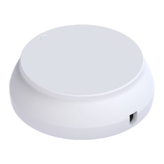
Auxiliary Care Radar • User Manual Data Cycle 50 ms Communication Interface RS-485/Wi-Fi Working Voltage 9 to 12 VDC Working Electric Current ≤ 200 mA @ 12 VDC Consumption < 2.4 W Working Temperature -40 °C to +50 °C (-40 °F to +122 °F) Dimension and Appearance Overview Refer to the figures below for the device dimension and appearance overview. -
Page 7: Installation Requirements
Auxiliary Care Radar • User Manual Cables Description Color Name Function +12 V 12 VDC Black Power ground Green RS-485A RS-485 communication port Blue RS-485B Yellow OC controlled signal VOH/VOL controller Brown Power ground Installation Requirements Install the device on the ceiling above the bed and point it to the chest of the person on the bed. The arrow on the front shell of the radar should point to the end of the bed. -
Page 8: Chapter 2 Software Instruction
Auxiliary Care Radar • User Manual Chapter 2 Software Instruction Device Connection You can connect the device via Wi-Fi or RS-485. Enter the corresponding information according to different connection modes. You can connect the radar via Wi-Fi. Before You Start Power on the radar (12 V). -
Page 9: Connection Via Rs-485
Auxiliary Care Radar • User Manual IP address: 192.168.4.1. Port: 20000. Connection Setting Click Confirm. You can connect the radar via the serial port. Open the software. Enable On/OFF. Select Serial Port. Select Port. Set BaudRate as 115200, Stop bit as 1, and Data bit as 8. No parity. Set Radar Address. -
Page 10: Read Software Version
Auxiliary Care Radar • User Manual The parameter “00-2.10;” in algorithm parameters means that the distance from the radar to the bed is 2.1 m. Edit the value according to the actual using environment. Parameter Settings Click and click Read after SoftVersion to read the software version. Click , set the address code, and click Set to edit the sub-device address. -
Page 11: Set Radar Status
Auxiliary Care Radar • User Manual The radar will not upload the detection data. Report once The radar will only upload data once for sub-device data searching in the RS-485 network. The report mode will not be saved if the device is powered off. It will restore to the default mode after re-powered on. -
Page 12: Upgrade
Auxiliary Care Radar • User Manual Upgrade You can upgrade the firmware version. Open the software. Press F1 button on the keyboard. Menu Page Enter IP Address and Radar Port (IP address: 192.168.4.1; radar port: 6666). Click Connect. Click Browse to select the firmware to be upgraded. Select Network Segment as the same network segment with radar and Mode as Auto. -
Page 13: Radar Network Configuration
Auxiliary Care Radar • User Manual Application Upgrade Click Confirm. Click Start Update. Upgrade Radar Network Configuration You can set the radar network. Open IRS60-5 Radar PC tool. Press F2 button on the keyboard. Enter IP Address and Port (IP address: 192.168.4.1; port: 6666). - Page 14 Auxiliary Care Radar • User Manual Network Configuration Click Connect. Set Work Mode as 3. Click Set. Set AP (Router) SSID and AP (Router) PWD. AP (Router) SSID means the router name. AP (Router) PWD means the router password. Set DHCPC as 0 (off). Set IP, Netmask, and gateway.
- Page 15 Auxiliary Care Radar • User Manual AP SSID means the Wi-Fi name. AP PWD means the Wi-Fi password. Set AP Click Set. Set Device ID as an integer (range: 1 to 999999999). Set Device Information...
- Page 16 Auxiliary Care Radar • User Manual Set data report type as 0. Set service IP as Hikcentral Pro service IP. Set service PORT as 20000. Set radar debug PORT as 6666. Set radar Passthrough data PORT as 20000. Set report interval as 0. Click Data Save.
Need help?
Do you have a question about the DS-TDSB00-EKH and is the answer not in the manual?
Questions and answers