
Related Manuals for Eneo ICB-62M2712M0A


Summary of Contents for Eneo ICB-62M2712M0A
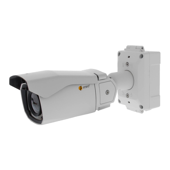
- Page 1 User Manual 1/2.8” Network Camera, 1920x1080, Day&Night, D-WDR, 2.7-12mm, Infrared, IP67 ICB-62M2712M0A...
-
Page 2: Table Of Contents
Table of content Parts supplied ..................... 5 Part names ......................6 Installation instructions ..................7 Using Grommet ............................. 7 Using RJ45 Easy Cap for Network cable ....................8 Recommended cable length into the Junction box base ............. 8 Pan & Tilt adjustments ..........................11 General Description .................. - Page 3 Safety instructions General safety instructions • • Keep the operating instructions in a safe place for later use. • Installation, commissioning and maintenance of the system may only be carried out by authorised individuals and in accordance with the installation instructions - ensuring that all applicable standards and guidelines are followed.
- Page 4 Class A device note This is a Class A device. This device can cause malfunctions in the living area; in such an event, the operator may need to take appropriate measures to compensate for these. WEEE (Waste Electronical & Electronic Equipment) Correct Disposal of This Product (Applicable in the European Union and other European countries with separate collection systems).
-
Page 5: Parts Supplied
Parts supplied • Network Camera • Operating Instruction • Mounting Template • Plastic Anchor: 6 x 30mm (4x) • Mounting Screw: 4 x 30mm (4x) • Hex Wrench: 3mm (1x) • Hinge Pin (1x) • Cable Tie (2x) • Grommet (2x) •... -
Page 6: Part Names
Part names Sunshield Junction Box Top Junction Box Base Bracket Body Case Dual window Hinge Pin 2x Water drain 2x Lock/Unlock Screw Inside of Opening Cover Micro SD MEMORY SD Card Slot LED Control Switch IP Reset (Default) RESET Junction Box Base User Network connector Ethernet from Cam. -
Page 7: Installation Instructions
Installation instructions Using Grommet can wrap the cable properly as illustrated. If it doesn’t wrap the cable properly, it could cause the water leakage problem. Using RJ45 Easy Cap for Network cable Recommended cable length intothe Junction box base • CABLE with RJ-45 Connector: 70~80mm •... -
Page 8: Recommended Cable Length Into The Junction Box Base
Install the mount onto a strong structure. Prepare the Junction box base and the accessaries for installation. 1. Locate the mounting template at the installation position and drill the ceiling or wall if needed. 2. Route the Power/Ethernet cables through the grommets from the wall. Insert the grommets onto the Junction box base. - Page 9 6. Assemble the Junction box top to the Junction box base using a hinge pin. Hinge can be inserted at either side for convinience. 7. Connects the Power/Ethernet cables from camera. 8. Cover the Junction box top and tighten with assembly screws (4pcs). Connections to RJ-45 connector Hinge pin Junction Box Top...
- Page 10 9. Set the camera’s orientation and tighten the Lock/Unlock screws using hex wrench. 10. After all the setting, close the Opening cover and tighten it. 11. Put the sunshield to the camera unit. Hex wrench Adjustment of viewing angle with a bracket CAUTION: Extreme care should be taken NOT to scratch the window in front of lens Care should be taken the cable is NOT to be damaged, kinked or exposed...
-
Page 11: Pan & Tilt Adjustments
Pan & Tilt adjustments • Unlock the screw on the camera bracket through using the torque wrench supplied. • Set the camera’s viewing angle then lock the screw on the bracket. Adjustment of viewing angle with a bracket 1. Pan limit: Pan is limited to +/- 90°. 80°... - Page 12 Sunshield Assembling • After all adjustments, assemble the sunsheild with the camera unit as illustrated. 1. Cover the sunsheild to the camera unit. 2. Slide foward to straight the camera front case. 3. Push down the front part of sunshield until clicking sound.
-
Page 13: General Description
General Description • Full HD, 2.3Mega Pixel, NETWORK CAMERA,1920x1080(30p/25p) • The best low light performance with SONY’s STARVIS sensor • ONVIF Conformance • Zero con guration • Cross Web Browsing (IE, Edge, Safari, Firefox, Chrome) • Adaptive web resizing depending on layout & resolution of display device by RESPONSIVE WEB •... -
Page 14: Speci Cation
ITEM ICB-62M2712M0A Imaging Sensor 1/2.8" Sony 2.3Mega pixel STARVIS CMOS Sensor Effective Pixels 1,920(H) x 1,080(V) approx. 2.07Mega pixels (Full-HD mode) Sensitivity Color Mode: 0.05 lux (LED off) , B/W Mode: 0.006 lux (LED off) Scanning mode Progressive Scan S/N Ratio... - Page 15 Security Multi User Authority, IP Filtering, HTTPS, Video Stream, Export/Import Network Time Sync. Synchronize Computer/NTP Server, Manual Software Reset Restart, Reset, Factory Default Auto Recovery Backup, Restore Remote Upgrade Using Web Browser Protocol TCP/IP, UDP, IPv4/v6, HTTP, HTTPS, FTP, UPnP, RTP, RTSP, RTCP, DHCP, ARP, Zeroconf, Bonjour Client Software Built-In Web, ONVIF Compatible 3rd Party VMS...
-
Page 16: Quick Network Setup
IP addresses. The network camera‘s default IP address is: 192.168.1.10. 5. Right clicking the device name in the eneo Site Manager will bring up the context menu. Use the ‘Open Device Web Site’ option to access the camera. 6. The web viewer login page will open up in your default web browser. -
Page 17: Full Menu Setup
Full Menu Setup Web viewer description XXX-XXXXXXXXXX (A) Menu button : Click the button to show or hide the setup menu bar. (B) Model name : Show a camera model name connected. (C) Select Language : Set the web viewer language English, Deutsch or French. (D) Main setup menu bar : Set the camera or network functions. -
Page 18: Setup Menu Table
Full Menu Setup Setup Menu Table Category Menu Player Control Pause, Snapshot, Record Display Window Fit, Full Screen, Custom LIVE VIEW Video Stream Stream1, Stream2, Stream3 Protocol HTTPS, HTTP, TCP, UDP PTZ Contol Zoom, Focus, Push AF PLAYBACK Event Search, Timeline Search, Timeline Bar Information General, System Information, Open source Information Source... - Page 19 Full Menu Setup Record verwrite when storage is full, Continuous record setting Record chedule Recycling Recycling Time Setting Storage Format, Remove, Storage Information Motion, VCA, Tamper, System, Manual, Network, Timer, Triggers Day/Night Event Actions Record, E-Mail, FTP, Video B SETUP Rules Event Processing, ONVIF Mapping Security...
-
Page 20: Live View
Full Menu Setup 1. LIVE VIEW Enter the live view menu on the Web Viewer. Player Control & Display Pause : Pauses the live view. Snapshot : Captures the image in .jpg format with the current stream resolution. Record : Records the live video in H.264 format into the equipped storage memory like SD, SDHC &... -
Page 21: Ptz Control
Full Menu Setup PTZ Control • ZOOM : Controls the lens optical zoom in/out for WIDE & TELE. • FOCUS : Adjusts the lens focus manually for NEAR & FAR. • PUSH AF : Gets the lens to focus at the push of a button. NOTE ZOOM, FOCUS &... -
Page 22: Playback
Full Menu Setup 2. PLAYBACK 0:00:00 Event Search Playback display using the event list. • Press the input bar to pop up EVENT DATE & TIME window and select the event TYPE. • Click SEARCH button to show up EVENT LIST. •... -
Page 23: Setup
Full Menu Setup 3. SETUP Enter the setup menu on the Web Viewer. 3-1. Information Shows the overall information about the system such as Model name, MAC address, IP address, Zeroconf, IP address, Firmware version, Server time, Running time, CPU usage, Inbound/Outbound Bandwidth and Open source list. - Page 24 Full Menu Setup 3-2-2. Stream 1920x1080@25fps Stream1, 2, 3 > COMPRESSION : Video compression codecs are available with H.264 profiles for all streams and additional MJPEG for stream3 only. > RESOLUTION : Each stream can have its individual resolution selected from its list. >...
- Page 25 Full Menu Setup > BITRATE : Indicates the transmission speed through the network and defines the overall picture quality along with the image resolution, frame rate, GOP size and the compression codec for H.264. A high value provides the higher image quality but the total sum of bitrates for the streams has to be considered in calculating the network duty.
- Page 26 Full Menu Setup 3-2-3. Image 2016-10-06 09:50:35 CAM1...
- Page 27 Full Menu Setup Basic > BRIGHTNESS: Adjusts the overall brightness of the scene. Increasing the value increases the brightness. > CONTRAST: Adjusts the contrast of the scene. Increasing the value increases the contrast. > SATURATION: Adjusts the color richness of the scene. Increasing the value increases the color richness.
- Page 28 Full Menu Setup > MODE : Selects how to control the exposure, AUTOMATIC or MANUAL. > SHUTTER : (Available only in MANUAL mode) Sets the shutter to a fixed value. > MAX. SHUTTER : Sets the maximum exposure time to limit long exposure at night or in low-light scenes.
- Page 29 Full Menu Setup VerticalView > MODE : Selects how to control the focus of the built-in Motor driven V/F lens or AF lens. • MANUAL : Focusing works during zoom operation only and stops thereafter. • AUTOMATIC : Focusing works steadily for sharp focusing on the object. In the case of a Motor driven lens, focusing resumes in about 7~8 seconds to save the lens lifetime when the focus gets lost.
- Page 30 Full Menu Setup [ WARNING ] LENS CALIBRATION is not necessary for regular installations. LENS CALIBRATION would only be necessary should you not be able to focus the lens after a zoom operation due to shock during transportation of the camera. To perform LENS CALIBRATION;...
- Page 31 Full Menu Setup > SWITCHING TIME : Delays switching the day/night filter to prevent from an undesirable transition. > THRESHOLD [D->N] : (Available in AUTOMATIC mode) Sets the threshold level for day->night switching. Decrease the value to switch at low luminance.
- Page 32 Full Menu Setup > WDR (Wide Dynamic Range) : • MODE : ON enhances the dynamic range by the extended adaptive tone reproduction. • LEVEL : Determines the strength of the dynamic range. Higher values increase brightness. > DEFOG : Enhances the image contrast automatically against fog. VerticalView >...
- Page 33 Full Menu Setup (Dynamic Digital Noise Reduction) > 2DNR : • MODE: ON reduces the noise by suppressing the spatial noise components. • LEVEL: Determines the strength of the noise reduction. Higher values reduce more noise but can also lead to loss of detail. VerticalView >...
- Page 34 Full Menu Setup VerticalView > MODE : ON displays the video in vertical view format, 16:9->9:16 for narrow streets, corridors or hallways. > ROTATION : Determines the orientation to rotate. Mode : On Rotation : 90 degree 3-2-4. Privacy Mask Mark ENABLE checkbox to activate the privacy masks.
- Page 35 Full Menu Setup To set the privacy mask (up to 8 privacy areas) : 1) Mark ENABLE checkbox. 2) In the video window, place the mouse cursor anywhere and click the right mouse button. A mini pop up appears. Select CREATE MASK AREA / DELETE MASK AREA. 3) In the video window, place the mouse cursor where you would like to create a mask.
-
Page 36: Record
Full Menu Setup 3-3. Record 3-3-1. Record > Mark OVERWRITE WHEN STORAGE IS FULL checkbox to allow the storage to be overwritten. > CONTINUOUS RECORD SETTING : Mark ENABLE checkbox to activate the continuous recording into the storage. > VIDEO STREAM : Selects the stream to be recorded into the storage. SD, SDHC or SDXC memory can be used as a storage device. - Page 37 Full Menu Setup 3-3-3. Recycling > Mark ENABLE RECYCLING checkbox to delete recorded video data in storage when certain time is passed. For example, if Recycling Time is set to 2 Months 1Day 0Hour, all the video data that passed 2 Months 1Day 0Hour will be deleted. >...
-
Page 38: Event
Full Menu Setup 3-4. Event 3-4-1. Triggers EVENT TRIGGERS menu defines and sets the parameters for the various event sources. [ Important NOTE ] Once the event is generated, the camera can record the video into the storage, output the alarm signal, email the event, send the video clip to FTP, boost the video frame rate, move to PTZ preset or send the event to the notification server. - Page 39 Full Menu Setup To set the motion detection area (up to 4 include-types and 4 exclude-types) : 1) Mark ENABLE checkbox. 2) In the video window, place the mouse cursor where you would like to make a detection window and click&drag the right button. The following window is then generated. •...
- Page 40 Full Menu Setup > Mark ENABLE checkbox to create & activate up to 3 VCAs. > NAME : Input the individual name for each VCA. To set the VCA detection area (up to total 3 VCAs including Line Cross, Field intrusion & Appear/Disappear) : 1) Mark ENABLE checkbox.
- Page 41 Full Menu Setup Tamper The camera can detect severe changes in the image caused by actions such as repositioning the camera or painting over of the lens and generates an alarm to alert. > Mark ENABLE checkbox to activate the tamper alarm. >...
- Page 42 Full Menu Setup Network : Used to trigger the event when the network connection fails. > Mark ENABLE checkbox to activate the network event. > DWELL TIME : Sets the time for the event once triggered by the network connection event. Timer Day/Night Timer...
- Page 43 Full Menu Setup 3-4-2. Actions EVENT ACTIONS menu defines and sets the parameters for how to treat the various event sources. Record > Mark ENABLE checkbox to enable recording into the built-in storage when the event occurs. > VIDEO STREAM : Selects the stream to be recorded when the event occurs. >...
- Page 44 Full Menu Setup > Mark ENABLE USE(SMTP) AUTHENTICATION checkbox if the mail server requires authentication. • USER NAME : Enter the user name as provided by the network administrator. • PASSWORD : Enter the password as provided by the network administrator. •...
- Page 45 Full Menu Setup > RECEIVER LIST : Enter the recipient’s email addresses as the receivers. > E-MAIL(SMTP) TEST : Enter the recipient's email address in RECEIVER and click the TEST button to test if the mail servers are functioning and the email address is valid.
- Page 46 Full Menu Setup • USER NAME: Enter the user name provided by the network administrator. • ANONYMOUS LOGIN: Mark ANONYMOUS LOGIN checkbox if anyone is permitted to access the FTP server. • PASSWORD: Enter the password provided by the network administrator. >...
- Page 47 Full Menu Setup Notification Server > Mark ENABLE checkbox to notify the event to the notification server when it occurs. • TYPE : Selects the network protocol to connect the notification server. • SERVER URL : Input the server URL of the notification sever. To enable the audio when the event occurs, copy the URL at SETUP>AUDIO and paste it on the server URL like http://x.x.x.x/setup/audio/audio.php •...
- Page 48 Full Menu Setup 3-4-3. Rules EVENT RULES menu defines and sets the parameters for what to do for the various event sources. Event Processing Event process lists have to be generated and can be edited for what to do when the event occurs.
- Page 49 Full Menu Setup > FTP : Mark the checkbox to use FTP as set in SETUP>EVENT>ACTIONS>FTP when the selected event occurs. > VIDEO BOOST : Select the video stream to be boosted up. Video boost is disabled if RECORD is enabled. [ NOTE ] >...
- Page 50 Full Menu Setup ONVIF Mapping Onvif mapping is provided to map the various events generated by this camera, but not defined by Onvif, to assign them to Onvif events for the Onvif compatible VMSes or NVRs. Two mappings for Motion and Alarm In are provided to be mapped and can be used by editing them.
-
Page 51: System
Full Menu Setup 3-5. System 3-5-1. Security Users ● Manages the user accounts by names, groups and authorities. > USERS : Can be added, edited or deleted. - Page 52 Full Menu Setup HTTPS Selects the CONNECTION MODE. Export / Import > HTTP : Transfers data without encryption. Supports a URL that only starts with "HTTP: " > HTTPS : Transfer data with encryption by Hypertext Transfer Protocol over SSL protocol. Supports a URL that only starts with "HTTPS: "...
- Page 53 Full Menu Setup To add a subnet of network addresses, these must be added in CIDR [ NOTE ] (Classless Inter-Domain Routing) notation. For example: entering 192.168.1.0/24 will add all the addresses in the range 192.168.1.1 to 192.168.1.254. Contact your network administrator for more detail.
- Page 54 Full Menu Setup 3-5-2. Date & Time Current Time Shows the current date and time. Clicking SAVE tap updates and saves the date and time with the selected time in NEW TIME. New Time Select one of the following server times. >...
- Page 55 Full Menu Setup 3-5-3. Network TCP/IP > IPv4 ADDRESS : • OBTAIN IP ADRESS VIA DHCP : Gets the IP address assigned by the DHCP (Dynamic Host Configuration Protocol) server. • STATUS : ‘Allocated’ shows that the IP address is obtained from the DHCP. •...
- Page 56 Full Menu Setup > PORT : • HTTP PORT : Use a port number in the range 1024-65535. Default is 80. • HTTPS PORT : Use a port number in the range 1024-65535. Default is 443. • RTSP PORT : Use a port number in the range 1024-65535. Default is 554.
- Page 57 Full Menu Setup DDNS (Dynamic Domain Naming Service) > Mark ENABLE checkbox to use DDNS. > DDNS server : Select the DDNS server to use. > Input REGISTERED HOST name, USER NAME, PASSWORD and INTERVAL. [ NOTE ] If the camera has not been registered to the DDNS host previously, the registration is required.
- Page 58 Full Menu Setup > START PORT & END PORT : RTP port range defines the range of the ports from which ports of the video/audio are automatically selected. This feature is useful if the camera is connected to a NAT router with manually configured port mapping. Limit the range of the ports permitted for RTP unicast/multicast by entering START PORT and END PORT.
- Page 59 Full Menu Setup UPnP UPnP is enabled by default so that the network camera can be automatically detected by operating systems and clients that support this protocol. > FRIENDLY NAME : Enter the name up to 32 alphanumeric characters like Model Name-MAC address.
- Page 60 Full Menu Setup 3-5-4. Language Six languages are available to select from English, Deutsch (German), Français (French), Polski (Polish), Suomi (Finnish), and (Korean). 3-5-5. Maintenance Maintain > RESTART : Restarts the camera without changing any settings. > RESET : Restarts and loads the factory settings but does not change IP address and PTZ settings.
- Page 61 Full Menu Setup Upgrade ● Bring the firmware file to the drop box or click the drop box to browse for the firmware file, and then click the UPGRADE button. Do not disconnect the power or network cable during firmware UPGRADE. [ CAUTION ] Setup Export ●...
-
Page 62: Help, 4 Eyes Principle
Full Menu Setup 4. Help Help the menu function. Click and pop-up the page about current menu description. 5. 4 EYES PRINCIPLE > Four Eyes Principle Setting : Two individual administrators(user authority) should approve to playback recorded data on Micro SD card for data security. One administrator should click Approval #1 and the other administrator should click Approval #2. -
Page 63: Troubleshooting
Troubleshooting If you suspect a problem is being caused by incorrect configuration or some other minor problem, consult the troubleshooting guide below. Upgrading the Firmware Firmware is software that determines the functionality of the network camera. One of your first actions when troubleshooting a problem should be to check the current firmware. - Page 64 Troubleshooting Poor image quality. Increased lighting can often improve image quality. Check that there is sufficient lighting at the monitored location. Check all image and lighting settings. Rolling dark bands or flickering Try adjusting the Exposure Control setting under AE in image.
- Page 68 VIDEOR E. Hartig GmbH Exclusive distribution through specialised trade channels only. VIDEOR E. Hartig GmbH Carl-Zeiss-Straße 8 63322 Rödermark/Germany Tel. +49 (0) 6074 / 888-0 Technical changes reserved Fax +49 (0) 6074 / 888-100 www.videor.com...
Need help?
Do you have a question about the ICB-62M2712M0A and is the answer not in the manual?
Questions and answers