Table of Contents
Advertisement
Available languages
Available languages
GROUND FAULT LOCATOR
Read and understand this material before operating or servicing this
equipment. Failure to understand how to safely operate this tool will
result in an accident causing serious injury or death.
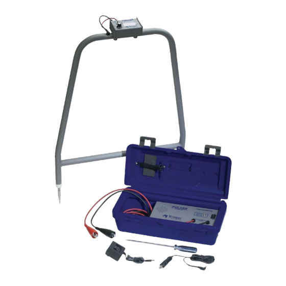
The Pulser is a Ground Fault Locator based on the earth gradient principle.
The PE2003 Pulser consists of:
• 2000H Transmitter
• 2000R Receiver
• "A" Frame assembly
• Cigarette lighter DC adapter charger
• AC charger
• Carrying case
• Ground stake
95E0027
INSTRUCTION MANUAL
PE2003 PULSER
© 2002
DANGER
Rev. A
Advertisement
Chapters
Table of Contents

Related Manuals for Textron Tempo PE2003


Summary of Contents for Textron Tempo PE2003
- Page 1 Failure to understand how to safely operate this tool will result in an accident causing serious injury or death. The Pulser is a Ground Fault Locator based on the earth gradient principle. The PE2003 Pulser consists of: • 2000H Transmitter • 2000R Receiver •...
- Page 2 This symbol is used to call your attention to hazards or unsafe practices which could result in an injury or property damage. The signal word, defined below, indicates the severity of the hazard. The message after the signal word provides information for preventing or avoiding the hazard.
-
Page 3: Table Of Contents
Figure 5. Nulling Receiver – Second Time ..... . . 5 1. DESCRIPTION The Model PE2003 Ground Fault Locator is based on the earth gradient principle. It will find the precise location of a path to ground fault in any buried wire or cable. -
Page 4: Operation
back through the ground to the transmitter ground stake. The current flow through the earth is measured by probing the ground along the cable path with the receiver “A” Frame. Since the current is directional, the receiver meter pulses or kicks with each transmitter pulse in the direction of the fault. The fault will be located midway between the receiver “A”... -
Page 5: Figure 3. Probing Cable Path – Reversal
Always adjust the receiver sensitivity for a less than full scale reading and correlate the transmitter beep with the receiver meter indication. 6. Move the “A” Frame in line with and down the faulted conductor path. Be sure to insert the “A” Frame probes deeply enough to insure good ground connection. -
Page 6: Special Fault Locating Problems
3. SPECIAL FAULT LOCATING PROBLEMS 1. Finding faults under concrete. Dissolve approximately 1/4 cup of salt in one gallon of water and soak two large sponges in the salt water. Wrap the sponges over the end of each probe and attach with a rubber band. Now proceed as described in 2.7. -
Page 7: Maintenance
Weight 2000H + Case ........3.3 kg (7.3 lb) 2000R + “A”... - Page 8 One-Year Limited Warranty Tempo warrants to the original purchaser of these goods for use that these products will be free from defects in workmanship and material for one year, excepting normal wear and abuse. For all Test Instrument repairs, you must first request a Return Authorization Number by contacting our Customer Service department toll free in the US and Canada 800 642-2155 Telephone +1 760 598-8900...
- Page 9 Le contacteur à impulsions est un localisateur de fuite de terre qui fonctionne à partir du principe du gradient terrestre. Le contacteur PE2003 comprend : • Émetteur 2000H • Récepteur 2000R •...
- Page 10 Ce symbole attire l'attention sur les risques de danger et de mauvaise utilisation pouvant causer des blessures ou des dommages matériels. Le mot-indicateur, défini ci-dessous, indique la sévérité du danger. Le message qui le suit explique comment prévenir ou éviter le danger en question. Dangers immédiats qui, à...
-
Page 11: Description
Figure 5. Récepteur de remise à zéro – Deuxième essai ..13 1. DESCRIPTION Le modèle PE2003 est un localisateur à impulsions de fuite de terre qui fonctionne à partir du principe du gradient terrestre. Il repère avec précision le chemin vers une fuite de terre dans un fil ou un câble souterrain. -
Page 12: Théorie
C. Théorie L’émetteur envoie des impulsions entre le conducteur défectueux et la terre. Cette méthode crée un courant continu (c.c.) vers le câble, à travers la fuite de terre, et revient de la terre vers la tige de mise à la terre de l’émetteur. Le débit de courant passant par la terre est mesuré... - Page 13 ÉMETTEUR CONTACTEUR ROUGE NOIR TIGE DE MISE À LA TERRE CÂBLE TERRE 5. Allumez le récepteur. Vérifiez l’état de la batterie en appuyant sur le bouton de test de la batterie et observez le contrôleur. Enfoncez dans la terre les sondes du cadre en « A ». (Voir la figure 3.) Si toutes les sondes sont correctement mises à...
-
Page 14: Problèmes Particuliers De Localisation De Fuite
8. Enfoncez le cadre en « A » à des angles droits ou perpendiculairement au chemin du câble par le point du premier signal nul. Répétez la procédure de la section 2.7 jusqu’à l’obtention d’un autre signal nul. Remarque : Le récepteur indiquera une valeur nulle lorsque les sondes enjambent exactement la fuite. -
Page 15: Spécifications
4. SPÉCIFICATIONS Caractéristiques électriques Émetteur 2000H Tension de sortie ......3400 V c.c. maximum Taux des impulsions de sortie (nominal) ....3,5 secondes Protection de tension . -
Page 16: Remplacement De La Batterie Du Récepteur
2. Tournez le capuchon du porte-fusible jusqu’à ce qu’il soit bien serré. 3. Chargez la batterie de l’émetteur avant de ranger l’appareil. Ne laissez jamais l’appareil inutilisé pendant une longue période avec une batterie faiblement chargée ou déchargée. B. Remplacement de la batterie du récepteur 1. - Page 17 éste, graves lesiones o incluso la muerte. El Generador de Impulsos es un Localizador de Fallas a Tierra basado en el principio de gradiente terrestre. El Generador de Impulsos PE2003 consta de: • Transmisor 2000H • Receptor 2000R •...
- Page 18 Este símbolo se utiliza para llamar su atención sobre los peligros o las prácticas no seguras de trabajo que podrían resultar en lesiones o daños a la propiedad. La palabra de aviso, definida a continuación, indica la gravedad del peligro. El mensaje después de la palabra de aviso proporciona información para prevenir o evitar el peligro.
-
Page 19: Descripción
Figura 5. Receptor de Anulación – Segunda Vez ....21 1. DESCRIPCIÓN El Localizador de Fallas a Tierra Modelo PE2003 está basado en el principio de gradiente terrestre. Encontrará la ubicación precisa de una trayectoria a una falla a tierra en cualquier alambre o cable soterrado. -
Page 20: Teoría
C. Teoría El transmisor emite impulsos entre el conductor defectuoso y la tierra. Esto establece un flujo de corriente de CC en el cable, a través de la falla a la tierra, y de vuelta a través de la tierra a la punta a tierra del transmisor. El flujo de corriente a través de la tierra se mide mediante el sondeo de la tierra a lo largo de la trayectoria del cable con el bastidor “A”... - Page 21 TRANSMISOR GENERADOR DE IMPULSOS ROJO NEGRO PUNTA A TIERRA CABLE TIERRA 5. Encienda el receptor. Verifique la condición de la pila oprimiendo el botón de verificación de pila y observando el medidor. Inserte las sondas del Bastidor “A” a la tierra. (Véase la Figura 3). Si todas las sondas hacen buena conexión a tierra, el receptor emitirá...
-
Page 22: Problemas Específicos Sobre
8. Inserte el Bastidor “A” en ángulos rectos o perpendicular a la trayectoria del cable, a través del punto de la primera anulación. Repita el procedimiento descrito en 2.7 hasta que ocurra la segunda anulación. Nota: El receptor se anulará cuando las sondas pasen a través de la falla de manera uniforme. -
Page 23: Especificaciones
4. ESPECIFICACIONES Eléctricas Transmisor 2000H Salida de tensión ......3400V CC máximo Tasa de impulsos de salida (nominal) ....3,5 segundos Protección de sobretensión . -
Page 24: Reemplazo De La Pila Del Receptor
3. Cargue la pila del transmisor antes de almacenar la unidad. Nunca permita que la unidad permanezca inutilizada durante un período de tiempo indeterminado con un pila baja o descargada. B. Reemplazo de la Pila del Receptor 1. Retire los dos tornillos en cualquiera de los lados del Receptor 2000R. 2.
Need help?
Do you have a question about the Tempo PE2003 and is the answer not in the manual?
Questions and answers