Table of Contents
Advertisement
Quick Links
Advertisement
Table of Contents

Related Manuals for Textron Tempo 525N-60


Summary of Contents for Textron Tempo 525N-60
- Page 3 Tempo is prohibited. REPRODUCTION AND DISTRIBUTION OF THIS TECHNICAL MANUAL IS AUTHORIZED FOR GOVERNMENT PURPOSES. Copyright © 2003 Tempo - a Textron Company. All rights reserved. Tempo Research, a Delaware Corporation PART NO. 52040535 REV 6 PRINTED IN U.S.A. ( 8/14)
- Page 4 OPERATING MANUAL – 525N - 60 OLTS Statement of Warranty Tempo warrants this product to be free from defects in materials and workmanship for a period of one (1) year from the date of shipment. During the warranty period we will, at our option, either repair or replace any product that proves to be defective.
-
Page 5: Table Of Contents
OPERATING MANUAL – 525N - 60 OLTS TABLE OF CONTENTS Section 1 - GENERAL INFORMATION PAGE: 1 Product Description..................1 Safety Terms & Precautions..............2 Unpacking & Inspection..................3 Reporting Shipping Damage, Service & Product Ordering......4 Preparation for Use..................5-12 Section 2 - QUICK START GUIDE PAGE: 13 Front Panel Controls &... -
Page 7: Section 1 - General Information Page
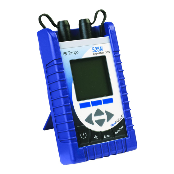
Section 1: General Information & Product Description Product Description The 525N-60 bi-directional optical test set is a compact handheld instrument incorporating an AutoTest feature, Optical Power Meter and Return Loss Meter. It can be used to measure Insertion Loss in Simplex tests. -
Page 8: Safety Terms & Precautions
OPERATING MANUAL – 525N - 60 OLTS Safety Terms in This Manual A WARNING identifies dangers that could result in personal injury or death. A CAUTION identifies hazards that could damage the instrument. A NOTE is followed by information that may be beneficial during the use of the instrument. -
Page 9: Unpacking & Inspection
Section 1: General Information & Product Description Laser Safety The 525N Series optical test sets are laser devices con- forming to the requirements CDRH, 1040, Subchapter J. While there is no potential for eye damage due to unaided direct expo- sure, users should always avoid looking directly into the output port. -
Page 10: Reporting Shipping Damage, Service & Product Ordering
To contact Tempo customer service, call (800) 642-2155 from 7 a.m. to 4:30 p.m. Pacific time. Inquiries may also be faxed to Tempo at (760) 598-5634, or sent via e- mail to fiberoptics@tempo.textron.com. Failure to follow this procedure may affect your claim for compensa- tion. -
Page 11: Preparation For Use
Section 1: General Information & Product Description Preparation for Use Charging the NiMH Battery Pack The 525N Series optical test set is shipped with a nickel-metal hydride (NiMH) battery pack installed. This battery pack must be charged before the instrument is used for the first time. To charge the NiMH battery pack, do the following: 1. - Page 12 OPERATING MANUAL – 525N - 60 OLTS Boot, Housing and Power Options Removing/Installing the Rubber Boot The 525N Series optical test set is fitted with a rubber boot that pro- vides impact and shock protection during use. This rubber boot incor- porates a swing-out stand, permitting convenient viewing of the dis- play when the instrument is used on the benchtop.
- Page 13 Section 1: General Information & Product Description Multiple Power Options The 525N Series optical test set features four power options: 1. Rechargeable nickel-metal hydride battery operation. Nickel- metal hydride battery pack required. 2. Concurrent nickel-metal hydride (NiMH) battery recharging (trickle charging) and AC operation. 3.
- Page 14 OPERATING MANUAL – 525N - 60 OLTS Alkaline Battery Operation For convenient field service, four (4) AA-type alkaline batteries may be used to power the 525N Series optical test set after the nickel- metal hydride battery pack has been removed. Alkaline batteries will provide up to 24 hours of continuous operation.
- Page 15 Section 1: General Information & Product Description LED Indicators, DC Input, and RS232 Port The DC input receptacle and RS232 port are located on the right side of the instrument when viewed from the front. If the protective rub- ber boot is installed, lift the flap for access. 1.
- Page 16 OPERATING MANUAL – 525N - 60 OLTS Snap-On Connector (SOC) Interface The optical power meter input of the 525N Series optical test set incorporates a Snap-On Connector (SOC) interface and is used with standard Tempo 10-series SOC adapters. SOC interfaces and adapters offer superior repeatability and are compatible with most industry standard fiber optic connectors.
- Page 17 Section 1: General Information & Product Description Cleaning the Instrument Interfaces To ensure absolute measurement integrity, it is essential that all instrument interfaces are cleaned before each use. Tempo recom- mends using a lint-free cloth, such as Texwipe TX404, and reagent- grade isopropyl alcohol to clean the SOC and UCI interfaces of the 525N optical test set.
- Page 18 OPERATING MANUAL – 525N - 60 OLTS Cleaning Fiber Optic Connectors To ensure absolute measurement accuracy and repeatability, fiber optic connectors must always be cleaned before conducting a fiber optic measurement. Dust and oil contamination on the connector end- faces, as shown at right, can result in abnormally high insertion loss readings and other anomalies.
-
Page 19: Section 2 - Quick Start Guide Page
Section 2: Quick Start Guide Front Panel Controls & Connectors POWER METER PORT - SOURCE/RETURN LOSS PORT - Optical Power Meter input Laser Source output equipped with equipped with SOC adapter. physical contact UCI interface. ARROW BUTTONS - SOFT KEYS - Moves highlighted Inputs various screen cursor left &... -
Page 20: Startup & Establish Reference Cables
OPERATING MANUAL – 525N - 60 OLTS AUTOTEST QUICK START GUIDE THIS IS A QUICK START REFERENCE ONLY. Refer to additional manual sections for detailed descriptions of how to configure and per- form testing with the 525N-60 Single-Mode OLTS. REMEMBER: To ensure absolute measurement accuracy, fiber optic connectors must always be cleaned before conducting a fiber optic measurement. - Page 21 Section 2: Quick Start Guide Establish Reference Cables Continued. . . 3B. Loopback Reference – Perform these steps on both Local and Remote units: From AutoTest Screen press the REF softkey. Use the UP/DOWN arrow keys to high light LOOP BACK Press ENTER button to select.
-
Page 22: Duplex Insertion Loss Test
OPERATING MANUAL – 525N - 60 OLTS Simplex Insertion Loss Test – 1310/1550 1. At the AutoTest Main Screen, for record purposes, use the Arrow buttons and Enter key to identify Cable and Fiber Names. NOTE: The unit that initiates the test becomes the Local. - Page 23 Section 2: Quick Start Guide Simplex Insertion Loss Test – 1310/1550 Continued. . . EXAMPLE OF TEST RESULTS: SCREEN 1 - 1. The screen will display test results for the Fiber. If Thresholds were either mask or manual selected, the first test screen will display Pass or Fail.
-
Page 25: Section 3 - Screen Functions & Descriptions Page
Section 3: Screen Functions & Descriptions AUTOTEST MAIN SCREEN At powerup, the splash screen will briefly display the 525N's firmware version and model number, and then display the Autotest Main Screen. From the Autotest Main Screen, Simplex Insertion Loss testing can be performed at 1310 &... -
Page 26: Reference Methond Screens
OPERATING MANUAL – 525N - 60 OLTS REFERENCE METHOD SCREENS From the Autotest Main screen, press the REF softkey. The Reference Method screen will be displayed. Use the UP/DOWN arrow keys to highlight SIDE BY SIDE LOOP BACK Press the Enter button to select the method. SIDE-BY-SIDE METHOD: Per the screen diagram, connect the Reference Cable from the Source/Return... -
Page 27: Setup Screens
Section 3: Screen Functions & Descriptions SETUP SCREENS From the Autotest Main screen, press the SETUP softkey. The Setup screen will be dis- played and automatically sequence through the following options: Wavelength? – Use the softkeys to set the unit to perform Insertion Loss testing at wavelengths of 1310nm, 1550nm or Both. - Page 28 OPERATING MANUAL – 525N - 60 OLTS SETUP SCREENS Continued. . . Edit Threshold? Mask – continued. . . Use the UP/DOWN arrow keys to highlight ) the Standard to be selected. Press enter to select. The L screen will be displayed. ARAMETERS From the L screen, input the fol-...
- Page 29 Section 3: Screen Functions & Descriptions SETUP SCREENS Continued. . . Edit Threshold? Edit – continued. . . Use the LEFT/RIGHT keys to highlight the digit to be set. Use the UP/DOWN keys to change the numbers. Press the Enter button to select, and move to the next line.
-
Page 30: Menu Screen
OPERATING MANUAL – 525N - 60 OLTS MENU SCREEN From the Autotest main screen, press the MENU softkey. The MENU screen will be displayed. Use the UP/DOWN arrow keys to highlight ) the function to perform, then press the Enter button to select. The following functions are available - VIEW DATA - Access and view up to 1000 test measurements stored in memory. -
Page 31: View Data Screens
Section 3: Screen Functions & Descriptions VIEW DATA SCREENS From the Menu screen, use the UP/DOWN arrow keys to highlight the View Data function, then press the Enter button to select. The stored test results menu will be displayed (by Date / Numeric). The latest result is always on top. - Page 32 OPERATING MANUAL – 525N - 60 OLTS VIEW DATA SCREENS Continued . . Pressing the More softkey will display additional test results for the first fiber - -- Thre Threshold setting entered for this test -- MgAB Difference between Threshold Setting and the Actual A to B Measurement -- MgBA...
-
Page 33: Tools Screens
Section 3: Screen Functions & Descriptions TOOLS SCREENS From the Menu screen, use the UP/DOWN arrow keys to highlight the TOOLS function, then press the E button to select. NTER Use the UP/DOWN arrow keys to highlight the function, then press the E button to select. - Page 34 OPERATING MANUAL – 525N - 60 OLTS TOOLS SCREENS Continued . . ZERO To Zero the Optical Power Meter and obtain a noise level baseline, do the following: From the Tools screen, use the UP/DOWN arrow keys to highlight the ZERO func- tion, then press the ENTER button to select.
- Page 35 Section 3: Screen Functions & Descriptions TOOLS SCREENS Continued . . DEFINE STANDARDS To create a selection of standard masks for use when calculating loss thresholds, perform the following: From the Tools screen, use the UP/DOWN arrow keys to highlight the DEFINE STANDARDS function, then press the...
-
Page 36: Opm/Source
OPERATING MANUAL – 525N - 60 OLTS OPM / SOURCE To perform Optical Power Meter measurements and turn the Laser Source on & off, do the fol- lowing: From the MENU screen, use the UP/DOWN arrow keys to highlight OPM / SOURCE then press the ENTER button to select. - Page 37 Section 3: Screen Functions & Descriptions OPM / SOURCE Continued . . AUTORANGE / HOLD- Use the Right arrow button to highlight the A box. When Measuring in Watts, use the UP/DOWN & ENTER buttons to toggle between: AutoRange - unit will seek the power range required to perform the test.
-
Page 38: Return Loss
OPERATING MANUAL – 525N - 60 OLTS RETURN LOSS To perform Return Loss measurements and turn the Laser Source on & off, do the following: From the MENU screen, use the UP/DOWN arrow keys to highlight RETURN LOSS then press the ENTER button to select. The RETURN LOSS METER screen will be displayed. - Page 39 Section 3: Screen Functions & Descriptions RETURN LOSS Continued . . 9. To store the test, press the SAVE soft- key. The screen will prompt you to iden- tify the Cable & Fiber. 10. Use the Arrow buttons and Enter key to identify the Cable name and Fiber Number.
-
Page 40: Send Message
OPERATING MANUAL – 525N - 60 OLTS SEND MESSAGE The 525N-60 has eight stored messages that can be sent between units when performing Insertion Loss testing. These messages are pre-pro- grammed and cannot be modified by the user - 1. Connect next fiber 2. -
Page 41: Section 4 - Specifications Page
Section 4: Specifications, Parts & Accessories Specifications Optical Power Meter Specifications Power Measurement Range in dBm +10dBm to -65dBm Wavelength > 850 - 1700nm 800nm to 1700nm Wavelength Range 850nm, 980nm, 1300nm, Calibration Points 1480nm, 1310, 1550nm, 1625nm Absolute Accuracy <... -
Page 42: Specification Summary Of Lasers
OPERATING MANUAL – 525N - 60 OLTS Specification Summary of Lasers Central Wavelength 1310nm±30nm 1550nm±30nm Spectral Bandwidth <170nm <170nm Stability ° Variation of < ±10 < ±0.25dB < ±0.25dB C from +17 to +40 ° < ±0.75dB < ±0.75dB Variation from 25 C from +0 to +50 Power Output Continuous Wave... -
Page 43: Parts & Accessories
Section 4: Specifications, Parts & Accessories Parts and Accessories To order accessories, SOC adapters, and parts, contact your local Tempo distributor. Accessories Description RS232 interface cable kit Printer serial cable kit Nickel-metal hydride battery pack Power transformer/NiMH charger Cleaning Supplies Description All-In-One connector cleaner Adapter cleaning wands... -
Page 44: Technical Support & Service
OPERATING MANUAL – 525N - 60 OLTS UCI Adapters Universal Connector Interface (UCI) adapters are available for most industry standard fiber optic connector types. Order additional adapters by specifying the codes listed below. Adapter Code Connector Type AE2-10 Diamond E-2000 APC-108/C Ceramic UCI, FC AMS-00... - Page 48 1390 Aspen Way · Vista, CA 92083 760-598-8900 · 800-642-2155 · Fax 760-598-5634 M – F · 7:00 a.m. – 4:30 p.m. · Pacific T ime Unit 3, Maesglas Industrial Estate Newport, NP20 2NN, UK +44 (0) 1633 223552 • Fax +44 (0) 1633 223948 www.tempo.textron.com...
Need help?
Do you have a question about the Tempo 525N-60 and is the answer not in the manual?
Questions and answers