
Related Manuals for Greenlee Fairmont H6400


Summary of Contents for Greenlee Fairmont H6400
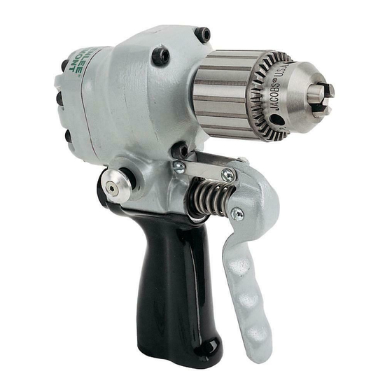
- Page 1 SERVICE MANUAL H6400, H6400C1 & VSD6400 REVERSIBLE DRILLS Read and understand all of the instructions and safety information in this manual before operating or servicing this tool. 999 1801.3 REV 4 © 2001 Greenlee Textron 1/01...
-
Page 2: Table Of Contents
Observe all of the safety information provided. Greenlee Textron / Subsidiary of Textron Inc. Purpose This manual is intended to familiarize all personnel with the safe operation and maintenance procedures for... -
Page 3: Important Safety Information
• Operation Manual • Specifications and Parts Manual Failure to observe this warning can result in severe injury or death. Greenlee Textron / Subsidiary of Textron Inc. Skin injection hazard: Oil under pressure easily punctures skin causing serious injury, gangrene or death. - Page 4 Do not disconnect tool, hoses or fittings while the power source is running or if the hydraulic fluid is hot. Hot hydraulic fluid can cause serious burns. Greenlee Textron / Subsidiary of Textron Inc. Do not reverse hydraulic flow. Operation with hydraulic flow reversed can cause tool malfunc- tion.
-
Page 5: Disassembly
If necessary, remove dowels (43) and gears (42). 5. Remove ring gear (2) and dowel pin (3) from handle (1). Greenlee Textron / Subsidiary of Textron Inc. Motor 1. Scribe a line across the motor cap (6) and handle (1) to align parts correctly during assembly. - Page 6 If necessary, remove dowels (57) and gears (55). 5. Remove ring gear (4) and dowel pin (5) from handle (1). Greenlee Textron / Subsidiary of Textron Inc. Motor 1. Scribe a line across the motor cap (47) and handle (1) to align parts correctly during assembly.
- Page 7 Remove spring pin (13) from handle. Turn torque output screw (10) counterclockwise until threads are free. Pull screw out of handle. Remove O-ring (11) and backup ring (12) from screw. Greenlee Textron / Subsidiary of Textron Inc. 4455 Boeing Dr., Rockford, IL 61109-2988 815/397-7070...
-
Page 8: Inspection
6. Inspect all other disassembled components for cracks, grooves or nicks. Greenlee Textron / Subsidiary of Textron Inc. Assembly (H6400C & H6400C1) Refer to the Illustration(s) and Parts List for correct orientation and placement of parts. -
Page 9: Assembly
5. Secure the links (34) to the handle (1) and trigger (37) using machine screws (35, 36) and nuts (39). Tighten to allow trigger to move freely. Greenlee Textron / Subsidiary of Textron Inc. Case Components 1. Install the ring gear (2) into the handle (1), aligning the notch in the ring gear with the notch in the handle. - Page 10 Secure with eight cap screws (49). Using the sequence shown here, torque to 9 Newton-meters (80 inch-pounds). Greenlee Textron / Subsidiary of Textron Inc. Torque Sequence Directional Spool 1. Assemble one O-ring (15) to the directional spool (14).
- Page 11 4. Allow the Loctite to cure before operating the tool. Greenlee Textron / Subsidiary of Textron Inc. 4455 Boeing Dr., Rockford, IL 61109-2988 815/397-7070...
- Page 12 (later models only) H6400C1 only 47A, 48 H6400C1 Models Only 47, 48 (H6400C only)
- Page 13 Button Head Socket ... 1 41298 F009117 Retaining Ring, .875, External ... 1 41760 F019817 Spring, Compression, .635 x .845 x 1.25" ... 1 Greenlee Textron / Subsidiary of Textron Inc. UPC No. Part No. Description 78-3310 40462 122755 Washer, Flat, .580 x .937 x .050, Stainless Steel ...
- Page 14 H6400C, H6400C1 and VSD6400 Reversible Drills Illustrations—VSD6400 Reversible Drill Greenlee Textron / Subsidiary of Textron Inc. 4455 Boeing Dr., Rockford, IL 61109-2988 815/397-7070...
- Page 15 41636 F017345 Connecting Link ... 1 41583 F016230 Slotted Round Head Machine Screw, #10 x 1-1/4 ... 1 Greenlee Textron / Subsidiary of Textron Inc. UPC No. Part No. Description 78-3310 41676 F018029K Hex Elastic Stop Nut, #10 ... 1...
- Page 16 Greenlee Textron / Subsidiary of Textron Inc. 4455 Boeing Drive, Rockford, IL 61109-2988 USA Customer Service (International): 815/397-7070 • Fax: 815/397-9247 Customer Service (North America): 800/435-0786 • Fax: 800/451-2632, 815/397-1865 Printed in the U.S.A. Canada Fax: 800/524-2853...
Need help?
Do you have a question about the Fairmont H6400 and is the answer not in the manual?
Questions and answers