
Subscribe to Our Youtube Channel
Related Manuals for Fukuda Denshi Dyna Scope 7700 Series


Summary of Contents for Fukuda Denshi Dyna Scope 7700 Series
- Page 1 Service Manual Issued No. Before setting up/maintenance, please read this service manual carefully. Keep this manual where it can be always referred to.
- Page 2 If you have any comment or request on usability, viewability, readability, or if you notice anything hard to understand on this service manual, please inform it to us. Fukuda Denshi Co., Ltd. Development & Production Support Dept. 2-35-8 Hongo Bunkyo-ku, Tokyo, 113-8420 Japan...
- Page 3 Revision History Model Name: DS-7700 System Service Manual Edition Revised Items Reason of the Revision Revised Date - New Edition 2010.11 The description of the TCON was Due to the addition of the TCON 2011.4 added. (For USA model types only) to USA model types.
- Page 4 Blank Page...
-
Page 5: Table Of Contents
Preface Read the “Safety Precautions” thoroughly before use to ensure correct and safe use of the product. Safety Precautions ii Expression Used in This Manual ......iii Classification by Display Unit Size ......iii Display Example in this Service Manual .....iii Key Display............iii Classification by System Construction ....iii Warning Label ............ -
Page 6: Safety Precautions
S afety Precautions Read the “Safety Precautions” thoroughly before use to ensure correct and safe use of the product. Make sure to follow the precautions indicated below, as these are important messages related to safety. Failure to follow this message may cause immediate threat of death or serious D A N G E R injury. -
Page 7: Expression Used In This Manual
E xpression Used in This Manual Classification by Display Unit Size The following model types for the DS-7700 system in this service manual are DS-7780, DS-7700L that referred to as “DS-7700 series”, and DS-7780W, DS-7700WL that referred to as “DS-7700W series”. - Page 8 General Expression Description Term The monitoring data is transmitted to the built-in telemetry module in- corporated in this unit via wireless network. Waveforms and numeric data can be displayed on this unit. Wireless Monitoring control is not possible on this unit. Network The monitoring data is transmitted to the built-in telemetry module in- Bed*...
-
Page 9: Warning Label
W arning Label Make sure to read the warning labels attached to the unit and comply with the requirements while operating the unit. Do not damage or erase the warning labels attached to the unit. C A U T I O N The warning labels contain descriptions important for handling and operating the unit properly and safely. -
Page 10: Measurement Unit For Each Parameter
M easurement Unit for Each Parameter The measurement units for this equipment are as follows. ( __ : Default Setting) Parameter Description Display Unit (Default Color) bpm (beats per minute) ST Level ST1/ST2 mm/ mV ST Ι, ST ΙΙ, ST ΙΙΙ, ST (Green) aVR, ST aVL, ST aVF, 12-lead ST Level... - Page 11 In case of DS-LANIII network, if the measurement unit for BP (mmHg/kPa) and temperature (C/F) is different between the bedside monitor and the central C A U T I O N monitor, the corresponding waveform and numeric data will not be displayed on the central monitor.
-
Page 12: Graphic Symbols
G raphic Symbols The following are the symbols and their meaning indicated on the equipment. Symbols Indicated on the Power Supply Part Symbol Description P otential Equalization Terminal Indicates the terminal to equalize the potential difference when inter- connecting the devices. Symbols Indicated on the Equipment Symbol Description... - Page 13 Symbol Description H eart Rate Synchronization Mark T his mark flashes synchronizing to the heartbeat. L ead OFF Indicates the lead-off condition. C heck Battery Indicates the low battery condition of the telemetry transmitter. R ecord/Stop Starts/stops the recording. A larm Silence/Event List Display/Too Far Alarm/Monitor Suspend Timer Displayed when alarm/too far alarm generates, or when monitoring is suspended using the timer.
-
Page 14: Precautions For Safe Operation Of Medical Electrical Equipment
Keep the unit clean to ensure proper operation of the next use. If the equipment is damaged and in need of repair, user should not attempt service. Label the unit “OUT OF ORDER” and contact Fukuda Denshi. Do not disassemble or remodel the equipment. -
Page 15: Precautions For Safe Operation Of Medical Telemetryxi
When interference or breakdown occurs in telemetry communication, the user is required to inform the zone manager and the overall manager of the prob- lems. The zone manager and overall manager are to deal with the problem properly and/or contact their nearest Fukuda Denshi representative for ser- vice. -
Page 16: Precautions For Use Of Bidirectional Wireless
TCON and to inform the Overall Manager of the problem. The Overall Manager is to deal with the problem properly and/or contact the nearest Fukuda Denshi representative for service. Precautions for Operation The Bidirectional Wireless Communications Module (TCON) uses radio waves to transmit data. -
Page 17: Precautions About The Maintenance
Maintenance, Modifications, and Repairs Fukuda Denshi is liable for the safety, reliability, and performance of its equipment only if; ・ Maintenance, modifications, and repairs are carried out by authorized personnel. -
Page 18: Non-Explosion Proof
N on-Explosion Proof 1 3 B Never operate the equipment in the presence of flammable anesthetics, high concentration of oxygen, or inside hyperbaric chamber. Also, do not operate the D A N G E R equipment in an environment in which there is a risk of explosion. Explosion or fire may result. -
Page 19: Precautions About Magnetic Resonance Imaging
Fukuda Denshi. It is the user’s responsibility to contact Fukuda Denshi to determine the com- patibility and warranty status of any connection made to another manufacturer’s equipment. - Page 20 Do not connect unit or cable not authorized by Fukuda Denshi to any I/O connector. If this system is used under an environment not fulfilling the specified condi- tion, not only that the equipment cannot deliver its maximum performance, the equipment may be damaged and safety cannot be ensured.
- Page 21 Be careful not to confuse the HUB used for the DS-LAN network and the HUB for the TCP/IP network. Fukuda Denshi is not liable of the operation caused by improper network connection. On the network configuration menu, when a setting is changed and [Enter] key is pressed, a caution message will be displayed.
- Page 22 Systems Use only the accessories specified for this device. Otherwise, proper function cannot be executed. For quality improvement, specifications are subject to change without prior no- tice. Do not use the touch panel with the film attached. Malfunction of the touch panel or damage may result.
- Page 23 PC/CF Card (contd.) The data transfer using the PC/CF card is possible only between the DS-7700 system central monitors and the DS-7600 system central monitors. There are partial restrictions when transferring data between DS-7700 system and DS-7600 system central monitors. The data cannot be transferred to the DS-7500 system or a bedside monitor.
- Page 24 Patient Admit / Discharge (contd.) When the discharge process is performed on the bedside monitor or other central monitors, the monitoring on the DS-7700 will not be suspended even if [Suspend] is selected for “Setup at Discharge”. When EMR link function is used, the patient admitted on EMR will be also ad- mitted on this unit.
- Page 25 Alarm Setup (contd.) The alarm messages will be displayed according to the priority. For the same alarm level, the alarm message for the newer alarm will be dis- played. Depending on the bedside monitor type and software version, the ventilator alarm factor may not be transmitted to the central monitor.
-
Page 26: Precautions About The Wired Network System (Ds-Lanii/Ds-Laniii)
Be careful not to confuse the HUB used for the DS-LAN network and the W A R N I N G HUB for the TCP/IP network. Fukuda Denshi is not liable of the operation caused by improper network connection. Use a 10M HUB for the DS-LANΙΙ network. If a 100M HUB or a switching HUB is used, a communication error may occur. -
Page 27: Precautions About The Wireless Network System
DS-LAN Precautions about the DS-LANIII Network System For the network-administrating monitor (Central ID: 001), the DS-7600 or DS-7700 must be set. The network will not function if the DS-5800N/NX/NXMB is set as the network-administrating monitor. Also, make sure not to duplicate the Central ID with other central monitors. -
Page 28: Disposing Of Equipment, Accessories, Or Components
For the alarm generation on the bedside monitor connected by wireless net- C A U T I O N work, maximum of 15 seconds delay will occur for the alarm generation on this unit. D isposing of Equipment, Accessories, or Components 2 3 B When disposing of the equipment, accessories, or components, use an indus- C A U T I O N... -
Page 29: Precautions About Rtc Or Data Backup
OFF, this clock is backed up by a lithium primary battery. If incorrect time is displayed when turning on the power, a low battery may be the cause. In such case, contact Fukuda Denshi service representative for re- placing the battery. -
Page 30: Electromagnetic Compatibility
E lectromagnetic Compatibility The performance of this device under electromagnetic environment complies with IEC60601-1-2: 2001+A1: 2004. P recautions for Safe Operation under Electromagnetic Influence 2 8 B If any sorts of electromagnetic wave, magnetic field, or static electricity exist around the device, noise interference or malfunction of the device may occur. If any unintended malfunction or noise occurs during monitoring, check the magnetic influence and take appropriate countermeasures. -
Page 31: Compliance To The Electromagnetic Emissions
●Compliance to the Electromagnetic Emissions The DS-7700 system is intended for use in the electromagnetic environment specified below. It should be assured that the DS-7700 system is used in such an environment. Guidance and manufacturer’s declaration - electromagnetic emissions The DS-7700 system is intended for use in the electromagnetic environment specified below. The customer or user of the DS-7700 system should assure that it is used in such an environment. -
Page 32: Compliance To The Electromagnetic Immunity (2)
●Compliance to the Electromagnetic Immunity (2) The DS-7700 system is intended for use in the electromagnetic environment specified below. It should be assured that the DS-7700 system is used in such an environment. Guidance and manufacturer’s declaration - electromagnetic immunity The DS-7700 system is intended for use in the electromagnetic environment specified below. -
Page 33: Recommended Separation Distances Between Portable And Mobile Rf Communications Equipment And The Ds-7700 System
●Recommended Separation Distances between Portable and Mobile RF Communica- tions Equipment and the DS-7700 System The DS-7700 system is intended for use in an environment in which radiated RF disturbances are controlled. The electromagnetic interference can be prevented by maintaining a minimum distance between portable and mobile RF communications equipment (transmitters) and the DS-7700 sys- tem as recommended below, according to the maximum output power of the communications equipment. - Page 34 C A U T I O N Federal Law restricts this device to sale by or on the order of a physician. ( F o r U S A )
-
Page 35: Telemetry Precautions (For Usa)
T elemetry Precautions (for USA) For proper management of the telemetry installation, consult your Fukuda Denshi representative concerning the following: Plan the installation of your telemetry system, taking into account your entire medical facility needs and plant requirements. Make sure the antenna system installed meets the facility and plant requirements. -
Page 36: Declaration Of Conformity (For Usa)
(1) This equipment may not cause harmful interference (2) This equipment must accept any interference received, including interference that may cause undesired operation. The responsible party for this equipment is: Fukuda Denshi USA, Inc. 17725-C NE 65 Street Redmond, WA 98052... - Page 37 Contents Preface This chapter describes the outline of this Chapter 1 General Description system. This chapter describes the electrical and Chapter 2 Specification mechanical specification of this system. Chapter 3 This chapter describes the cable connection of this system. Names of Parts and Their Function This chapter explains the block diagram of Chapter 4 Wiring Diagram this system and its function.
- Page 38 Preface Chapter1 General Description Safety Precautions ·························································· ii General Description ·····················································1-2 Expression Used in This Manual ······························ iii Features ·································································1-3 Classification by Display Unit Size ······················ iii Display Example in this Service Manual ············· iii Key Display ························································· iii Classification by System Construction ················ iii Chapter 2 Specification Warning Label ···························································v Measurement Unit for Each Parameter ····················...
- Page 39 Chapter 6 Assembly Diagram Chapter 10 Maintenance DS-7700W/ LC-7019FT Alarm Indicator Assembly DIP Switch / Rotary Switch Setup ······························10-2 ········································································· 6-2 DIP Switch Setup··················································10-2 DS-7700W LCD Block Assembly (1)················ 6-3 Rotary Switch Setup ·············································10-2 DS-7700W LCD Block Assembly (2)················ 6-4 DS-7700W LCD Block Assembly (3)················...
- Page 40 Blank page xxxvi...
-
Page 41: Equipment
Chapter 1 General Description This chapter describes the outline of this equipment. General Description ..........1-2 Features ..............1-3 -... -
Page 42: Chapter1 General Description
General Description The DS-7700 System Central Monitor (hereinafter referred to as DS-7700) is a central monitor which supports various system construction combining wired and wireless network in general ward, ICU, etc. The DS-7700 series have a15 inch, the DS-7700W series have a 19 inch easily viewable color LCD. For the DS-7700W series monitors, an extended display unit (LC-7019 series) can be connected. -
Page 43: Features
Features DS-7700/DS-7700W series Easily viewable color LCD of 15-inch (DS-7700 series) or 19-inch (DS-7700W series) is used. Maximum of 16 beds connected to the wireless network (LX-5120/5160, HLX-501/561 etc.) or to the wired network (DS-LANII/DS-LANIII) can be monitored. An optional diversity antenna function is available which uses 2 telemetry antennas. With this function, the telemetry antenna can be switched to the other one if reception sensitivity decreases. - Page 44 Extended Display Unit LC-7019 series LC-7019FT Easily viewable 19 inch color LCD When connected to a DS-7700W series central monitor, multi display or full disclosure can be displayed. On the DS-7700W series, connecting the optional mouse and keyboard allows mouse control of the touch panel keys and keyboard input.
- Page 45 Chapter 2 Specification Specification / Performance ........2-2 Specification .............2-2 Performance.............2-4 ● DS-7700/DS-7700W series ......2-4 ● Extended Display Unit LC-7019 series ..2-8 LC-7019FT............2-8 -...
-
Page 46: Specification / Performance
Specification / Performance This section states the specification and performance of the DS-7700/DS-7700W series central monitor and the display unit LC-7019 series. Specification Size [Central Monitor] DS-7700 series :350±30(W) × 244±30(D) × 387±30(H)mm (not including the protrusion) DS-7700 W series :434±30(W) ×... - Page 47 Waterproof Level :IPX0 (no protection) Usage in Presence of Flammable Gas :Equipment inappropriate to use in presence of air/flammable anesthetics, or oxygen or nitrous oxide/flammable anesthetics. Operation Mode :Continuous Operating Equipment Power Supply DS-7700/DS-7700W series Voltage :AC 100V-240V AC 115V (USA) Frequency :50/60 Hz Power Consumption :150 VA...
-
Page 48: Performance
Performance ● DS-7700/DS-7700W series Display Display :TFT Color LCD Size :DS-7700 Series :15 inch (diagonal) DS-7700W series :19 inch (diagonal) Resolution :DS-7700 Series :1024 × 768 XGA DS-7700W series :1280 x 1024 SXGA Waveform Trace :Stationary Trace Waveforms :Max. 24 waveforms Parameter :ECG, RESP, TEMP, SpO (Arterial Oxygen Saturation), BP, NIBP,... - Page 49 Respiration Meas. Method :Depends on the transmitter, bedside monitor. Meas. Range :0, 4 to 150Bpm Frequency Characteristic :Depends on the transmitter, bedside monitor. Meas. Current :Depends on the transmitter, bedside monitor. BP Value Meas. Range :Depends on the transmitter, bedside monitor. Frequency Characteristic :Depends on the transmitter, bedside monitor.
- Page 50 INVOS (rSO Meas. Method :Depends on the bedside monitor. Meas. Range :Depends on the bedside monitor. Meas. Accuracy :Depends on the bedside monitor. Meas. Method :Depends on the bedside monitor. Meas. Range :Depends on the bedside monitor. Meas. Accuracy :Depends on the bedside monitor. SPIRO (MVe, PEAK, PEEP, TVe, TVi) Meas.
- Page 51 Telemetry No. of Receiving Beds :DS-7780: Max. 8 beds DS-7780W: Max. 8 beds DS-7700L: none DS-7700WL: none Frequency :433.0625 to 434.7875 MHz Method :Crystal Controlled PLL Type Double Super Heterodyne Transmitter :LX-5120/5230/7120/7230, HLX-501, Bedside Monitor (with HLX-501 or equivalent) Antenna Connector :F Type :...
-
Page 52: Extended Display Unit Lc-7019 Series
● Extended Display Unit LC-7019 series LC-7019FT Display Display :TFT Colour LCD Size :19 inch (diagonal) Resolution :1280 x 1024 SXGA Waveform Trace :Stationary Trace Waveforms :Max. 24 waveforms Function Control Touch Screen Method Input/Output Interface Video Connector (Use the accessory cable) Serial Connector (Use the accessory cable) External Equipment Connector (Use the optional accessories) Infrared Remote Control Input (Use the optional accessories) - Page 53 Chapter 3 Names of Parts and Their Functions Names of Parts and Their Functions....... 3-2 DS-7700/DS-7700W series ........3-2 Front Side ............3-2 Rear Side............3-2 Right Side ............3-3 Left Side............3-3 LC-7019FT ............3-4 Front Side ............3-4 Rear Side............
-
Page 54: Names Of Parts And Their Functions
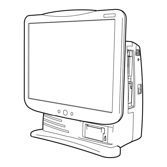
Names of Parts and Their Functions DS-7700/DS-7700W series Front Side Alarm Indicator Notifies the alarm by flashing. Remote Control Sensor Main Power Supply LED Receives the infrared Lights when the AC power is remote control signal. supplied. Light will be OFF when the AC Ambient Light Sensor power is not supplied. -
Page 55: Right Side
Right Side PC Card Slot PC card such as flash memory card is inserted here. PC Card Access Indicator Indicates PC card access status. Maintenance Cover Protective cover for the booster output setup. CF Card Slot Insert only the specified CF card here. -
Page 56: Front Side
LC-7019FT Front Side Alarm Indicator Notifies the alarm by flashing. Remote Control Sensor Main Power Supply LED Receives the infrared Lights when the AC power is remote control signal. supplied. Light will be OFF when the AC power is not supplied. Ambient Light Sensor When the AC power is Detects the ambient light. -
Page 57: Left Side
Left Side External Equipment Connector The specified PS/2 external equipment can be connected PS/2 external equipment can be connected to the LC-7019FT via the specified interface cable. Power Supply Switch Turns ON/OFF the device. Video Connector Connect the DS-7700W series central monitor via digital display connection cable. -
Page 58: Connection To Other Devices
Connection to other devices Connecting the DS-LAN By connecting the DS-5000 system bedside monitors or DS-7000 system bedside monitors, a wired network system can be constructed. Maximum of 48 beds for the DS-LANII and maximum of 100 beds for the DS-LANIII network can be connected. -
Page 59: Connection To Serial Connector
Connection to Serial Connector The DS-7700 system is equipped with 3 serial connectors (COM1, COM2, COM3) to connect various external equipments. Securely connect the cable of the respective equipment to one of the connectors. To validate the connection, the connected equipment must be properly set on the DS-7700 serial communication setup menu. -
Page 60: Connecting The Extended Display Unit
For the DS-7700W series centaral monitors,an extended display uinit (LC-7019 series) can be connected. Use only the cables specified by Fukuda Denshi. Use of other cables may W A R N I N G cause malfunction or damage this equipment. -
Page 61: L760T-C (Eizo )
Digital Display Connection Cable for DVI and CJ-726 Relay Cable for serial communication provided as optional accessories for the DS-7700. Use only the cables specified by Fukuda Denshi. Use of other cables may W A R N I N G cause malfunction or damage this equipment. - Page 62 Connection Procedure Refer also to the L760T-C Operation Manual. (1) Connect the touch panel cable (accessory for the L760T-C) and CJZ-01SS3 Digital Display Connection Cable to the L760T-C. (2) Connect the CJ-726 Relay Cable to the touch panel cable. Touch Panel Cable (accessory for the L760T-C) CJZ-01SS3 CJ-726...
-
Page 63: Chapter 4 Wiring Diagram
Chapter 4 Wiring Diagram DS-7700/DS-7700W Monitor Unit ······························4-2 Extended Display Unit [LC-7019FT]··························4-4 -... -
Page 64: Ds-7700/Ds-7700W Monitor Unit
DS-7700/DS-7700W Monitor Unit The diagram below explains the block diagram of the DS-7700/DS-7700W and its function. Display Block Touch Panel Unit ③ LCD Unit Inverter Unit (for Back Light) ④ ⑤ ① Speaker ② Power Display CPU Board ⑦ PCB-7449(DS-7700) PCB-7327(DS-7700W) ⑥... - Page 65 CAUTION To repair connector or cable, replace the entire board or contact your local Fukuda Denshi factory for service. Parts may be damaged when reparing/detaching connectors on the board as they are very small and pin-pitch is very narrow. Handle flexible flat cable (FFC) with care. Do not touch a terminal of FFC cable or use it in reverse as it may not function properly or may result in irreversible damage.
-
Page 66: Extended Display Unit [Lc-7019Ft]
Extended Display Unit [LC-7019FT] Touch Panel Unit Inverter Unit ③ (for Back Light) LCD Unit ④ ① ② ⑤ Power Multi-Display CPU Board PCB-7328 ⑦ ⑥ ⑧ Sensor Board Alarm Pole Board Multi-Display PCB-6918 PCB-7340 Sub Board PCB-7357 ⑨ Power Supply Unit AC input ⑩... - Page 67 CAUTION To repair connector or cable, replace the entire board or contact your local Fukuda Denshi factory for service. Parts may be damaged when repairing/detaching connectors on the board as they are very small and pin-pitch is very narrow. List of connection cables Cable Note ①...
- Page 68 Blank page -...
- Page 69 Chapter 5 Spare Parts List DS-7700W Main Unit Block Spare Parts······················5-2 DS-7700 Main Unit Block Spare Parts ·························5-7 Periodic Replacement Parts·······································5-11 LC-7019FT Main Unit Block Spare Parts ···················5-12 -...
-
Page 70: Ds-7700W Main Unit Block Spare Parts
DS-7700W Main Unit Block Spare Parts The spare parts of the main unit of DS-7700W block are as follows: Item Code Item Name Model Name Note 9F0101320 Main CPU board PCB-7325 SAS 9F0101330 Extended board PCB-7236 SAS 9F0102530 RF CPU board PCB-6945 SAS (DS-7780W only) 9F0101360... - Page 71 The spare parts of the main unit cover assembly of the DS-7700W are as follows: Item Code Item Name Model Name Note ― 5G0023050 Main Unit front cover – SU ― 6C005489B Main Unit rear cover ― 6C0054900 Main Unit stand ―...
- Page 72 The spare parts of the CPU Unit of the DS-7700W Main Unit are as follows: Item Code Item Name Model Name Note ― 9H0102360 CPU right case (7700) SU ― 9H0102350 CPU rear case (7700) SU ― 9H007122A CPU front case (7700) SU ―...
- Page 73 The spare parts of the hinge block of the DS-7700W are as follows: Item Code Item Name Model Name Note ― 6C0059930 19 inch touch panel torque hinge ― 9H0067950 Hinge cover (A) SU ― 9H0067960 Hinge cover (B) SU ―...
- Page 74 The packaging items of the DS-7700W main unit are as follows: Item Code Item Name Model Type Note ― 4M001616A Standard carton box ― 4M0038100 Partition carton (W1) ― 4M001617A Carton box (LC) ― 4M0038110 Partition carton (W2) ― 4M0037990 Film box ―...
-
Page 75: Ds-7700 Main Unit Block Spare Parts
DS-7700 Main Unit Block Spare Parts The spare parts of the main unit of DS-7700 block are as follows: Item Code Item Name Model Name Note 9F0102060 Main CPU board PCB-7325 SAS 9F0102530 RF CPU board PCB-6945 SAS (DS-7780 only) 9F0101360 RF Mother board (For 8 beds) PCB-7329 SAS TYPE8... - Page 76 The spare parts of the main unit cover assembly of the DS-7700 are as follows: Item Code Item Name Model Name Note ― 5G0023050 Main Unit front cover - SU ― 6C005489B Main Unit rear cover ― 6C0054900 Main Unit stand ―...
- Page 77 The spare parts of the CPU Unit of the DS-7700 Main Unit are as follows: Item Code Item Name Model Name Note ― 9H0102360 CPU right case (7700) SU ― 9H0102350 CPU rear case (7700) SU ― 9H007122A CPU front case (7700) SU ―...
- Page 78 The spare parts of the hinge block of the DS-7700 are as follows: Item Code Item Name Model Name Note ― 6C0059930 19 inch touch panel torque hinge ― 9H0067950 Hinge cover (A) SU ― 9H0067960 Hinge cover (B) SU ―...
- Page 79 The standard accessories of DS-7700 main unit are as follows: Item Code Item Name Model Name Note 4A006037B Power Cable CS-18 4A006048D Power Cable CS-24 For USA ― 5G002053A Parts Replacement Label 4L010574* Operation Manual Depends on the software ― version 4L010575* Maintenance Manual...
-
Page 80: Lc-7019Ft Main Unit Block Spare Parts
LC-7019FT Main Unit Block Spare Parts The spare parts of the LC-7019FT Main Unit are as follows: Item Code Item Name Model Name Note 9F0103020 Multi Display I/F Board PCB-7328 SAS 9F0103030 Multi Display Sub Board PCB-7357 SAS 9F0053540 Sensor Board PCB-6918 SAS 9F0101510 Alarm Board... - Page 81 The spare parts of the display block of the LC-7019FT are as follows: Item Code Item Name Model Name Note 5G002520A LCD front case (W) SU 9H0103350 LCD rear case SU 7019FT 6C0055210 Alarm cover 6C0055350 Alarm pole drip-proof sheet 9H0103360 LCD chassis SU 7019FT 6C0055350...
- Page 82 The packaging items of the LC-7019FT main unit are as follows: Item Code Item Name Model Name Note A set of LC-7019FT packaging 4M0101630 mediums 5H0097020 Standard Accessories case 5H0105010 Temperature label -...
- Page 83 Chapter 6 Assembly Diagram DS-7700W/ LC-7019FT Alarm Indicator Assembly ..................6-2 DS-7700W LCD Block Assembly (1) ...... 6-3 DS-7700W LCD Block Assembly (2) ...... 6-4 DS-7700W LCD Block Assembly (3) ...... 6-5 DS-7700W CPU Block Assembly ......6-6 DS-7700 RF Block Assembly ......... 6-7 DS-7700W Main block Assembly ......
-
Page 84: Ds-7700W/ Lc-7019Ft Alarm Indicator Assembly
DS-7700W/ LC-7019FT Alarm Indicator Assembly -... -
Page 85: Ds-7700W Lcd Block Assembly (1)
DS-7700W LCD Block Assembly (1) -... -
Page 86: Ds-7700W Lcd Block Assembly (2)
DS-7700W LCD Block Assembly (2) -... -
Page 87: Ds-7700W Lcd Block Assembly (3)
DS-7700W LCD Block Assembly (3) -... -
Page 88: Ds-7700W Cpu Block Assembly
DS-7700W CPU Block Assembly -... -
Page 89: Ds-7700 Rf Block Assembly
DS-7700 RF Block Assembly -... -
Page 90: Ds-7700W Main Block Assembly
DS-7700W Main block Assembly -... -
Page 91: Lc-7019Ft Lcd Block Assembly (1)
LC-7019FT LCD Block Assembly (1) -... -
Page 92: Lc-7019Ft Lcd Block Assembly (2)
LC-7019FT LCD Block Assembly (2) -... -
Page 93: Lc-7019Ft Lcd Block Assembly (3)
LC-7019FT LCD Block Assembly (3) -... -
Page 94: Lc-7019Ft Assembly (1)
LC-7019FT Assembly (1) -... -
Page 95: Lc-7019Ft Assembly (2)
LC-7019FT Assembly (2) -... -
Page 96: Lc-7019Ft Assembly (3)
LC-7019FT Assembly (3) -... -
Page 97: Lc-7019Ft Assembly (4)
LC-7019FT Assembly (4) -... - Page 98 Blank page -...
- Page 99 Chapter 7 Software Upgrade Procedure Software version verification ........7-2 DS-7700/DS-7700W Series Software Upgrade..7-3 Normal Installation..........7-4 Force Installation ........... 7-5 LC-7019FT Software Upgrading......7-6 -...
-
Page 100: Software Version Verification
Software version verification The current software version can be verified on the following screen. Press the [Menu] → [System Configuration] → [Pre-Set] → [Version Info.] keys. The software version of each unit and currently attached module type will be displayed. ・DS-7700 Software Version ・Display Unit Software Version ・Arrhythmia Module... -
Page 101: Ds-7700/Ds-7700W Series Software Upgrade
Software Upgrade This chapter explains about the software upgrade procedure. DS-7700/DS-7700W Series Software Upgrade Software upgrading for DS-7700/DS-7700W can be done with a Compact Flash Card (CF card) with the upgrading program. Software upgrading can be performed by switching ON the device after inserting the CF in the CF card slot. -
Page 102: Normal Installation
Normal Installation This chapter describes the software upgrade procedure of a normal installation. While the power is ON, check that the LED indicator lights in green when the CF card for upgrading is inserted in the CF card slot located on the right sideof the main unit. (Installation cannot be performed when the LED indicator does not light in green.) Power OFF/ON the switch and make sure the upgrading starts automatically. -
Page 103: Force Installation
Force Installation This section describes the software upgrade procedure of a force installation. This process requires a Philipps screwdriver (No.2) While the power is ON, check that the LED indicator lights in green when the CF card for upgrading is inserted in the CF card slot located on the right side of the main unit. (Installation cannot be performed when the LED indicator does not light in green.) Remove the side cover on the right side of the main unit with the system powered OFF. -
Page 104: Lc-7019Ft Software Upgrading
LC-7019FT Software Upgrading Connect the LC-7019FT to a DS-7700W series when software upgrading is performed. Software upgrading for DS-7700/DS-7700W can be done with a Compact Flash Card (CF card) with the upgrading program. Software upgrading can be performed by switching ON the device after inserting the CF card in the CF card slot of the DS-7700W series. -
Page 105: Chapter 8 Caution Label
Chapter 8 Caution Label Caution Label ............8-2 DS-7700/DS-7700W series ........8-2 LC-7019FT ............8-3 -... -
Page 106: Ds-7700/Ds-7700W Series
Caution Label DS-7700/DS-7700W series -... - Page 107 LC-7019FT ・ Read the Operation Manual thoroughly before installing or using the device. ・ Use only the supplied AC power cable. ・ Before using the device, make sure that the device works normally. -...
- Page 108 Blank page -...
- Page 109 Chapter 9 Troubleshooting Wired Network, TCP/IP Network ····························9-2 Telemetry ·······························································9-2 Bed Registration ·····················································9-3 Alarm ······································································9-4 Display····································································9-6 Built-in Recorder·····················································9-9 Laser Printer·························································9-11 PC/CF Card··························································9-12 EMR Link Function ···············································9-13 General·································································9-13 Mouse / Keyboard ················································9-14 Slave Monitor ·······················································9-15 Bed transfer/exchange ·········································9-15 Extended Display Unit ··········································9-16 TCON (for USA) ···················································9-16 -...
-
Page 110: Wired Network, Tcp/Ip Network
:Inappropriate HUB is used. :Use a 10Base repeater HUB for DS-LAN ΙΙ network and a switching HUB Solution recommended by Fukuda Denshi for DS-LAN ΙΙΙ network. Make sure to use the correct HUB for each network. Cause 4 :On the DS-LANII network, DS-5800 is set as the network-administrating monitor. -
Page 111: Bed Registration
Cause 3 :OFF is selected for the AC filter. Solution :Select [ON] for the “AC Filter” on the ECG setup menu. Cause 4 :OFF is selected for the ECG drift filter. Solution :Select [ON] for the ECG drift filter on the ECG setup menu. The waveform is not transmitted or displayed. -
Page 112: Alarm
Alarm Alarm does not generate. Alarm is not displayed. Cause 1 :Alarm is suspended. Solution :Cancel the [Alarm Suspend] selection on the “Menu” screen. Cause 2 :Alarm is silenced. Solution :Press the [Resume All Al. Sound] on the "Menu" screen. Cause 3 :Alarm is set to [OFF] for the parameter. - Page 113 The “Cannot analyze” message is displayed. Cause :A noise is interfering on the ECG and arrhythmia analysis is suspended for more than 30 seconds. When “Suspend Arrhy. analysis during Noise Interference” under Alarm Related Setup is set to [ON], and arrhythmia analysis has been continuously suspended for more than 30 seconds due to continuous noise interference or EMG, this message will generate.
-
Page 114: Display
Display A certain parameter cannot be displayed. Cause 1 :The parameter is not set to be displayed on the bedside monitor connected to the network. Solution :Set the parameter to be displayed on the bedside monitor. Cause 2 :The parameter is set OFF on the “Parameter ON/OFF” menu. Solution :Set the parameter [ON] on the “Parameter ON/OFF”... - Page 115 Artificial pacemaker is not displayed. Cause 1 :“Pacemaker” is set to [Not Used] on the patient admit menu. Solution :Select [Used] for the pacemaker use on the patient admit menu. Cause 2 :“Pace Pulse” is set to [OFF] on “the ECG setup” menu. Solution :Set the “Pace Pulse”...
- Page 116 Cause 3 :The sensor is defective. Solution :Replace the sensor. Cause 4 sensor is not firmly connected to the SpO input connector. :SpO Solution :Make sure the SpO sensor is securely connected. Cause 5 :Sensor is exposed to light. Solution :Place a black or dark cloth over the sensor to avoid direct sunlight.
-
Page 117: Built-In Recorder
Cause 2 :CO is measured on the DS-5400 Bedside Monitor with the software version V03-02 or prior. Solution :Update the DS-5400 software version. Cause 3 is measured on the DS-5300 Bedside Monitor. :CO Solution :The DS-5300 is not capable to transmit the CO data. - Page 118 Properly set the recording paper inside the cassette, and turn ON the power of the monitor. Cut the recording paper along the perforated line. The ECG waveform is recorded, but the second and third waveforms are not recorded. Cause :The second waveform and the third waveform are not set on the recording setup menu. Solution :Set the second waveform and third waveform on each recording setup menu.
-
Page 119: Laser Printer
Laser Printer The recording is not performed on the laser printer. Cause 1 :The paper cassette is empty. Solution :Install the recording paper in to the paper cassette. Cause 2 :The paper cassette is not firmly closed. Solution :Close the paper cassette properly. Cause 3 :Other monitor is in process of recording. -
Page 120: Pc/Cf Card
Printer output is garbled. Cause :The power of the printer was reset during recording. Solution :When resetting the printer power, it should be done after the recording is complete. The [Rec.] key turned to gray and cannot be pressed. Cause :The stacked data has reached the maximum recordable quantity (64). -
Page 121: Emr Link Function
Cause 3 :The CF card is write-protected. Solution :Cancel the write-protect function. EMR Link Function The “Check EMR comm.” Message is displayed. Cause 1 :There is a communication failure between the DS-7700 system and the patient data server. Solution :Check the communication status of the DS-7700 system, patient data server, and EMR machine. -
Page 122: Mouse / Keyboard
The display is not clear. Cause :The display brightness is not adjusted. Solution :Due to the LCD display characteristic, the visible range is limited. Adjust to the appropriate brightness. The system does not start although the power switch is turned ON. Cause 1 :The power cable is not connected. -
Page 123: Slave Monitor
The keyboard stopped functioning. Solution :The keyboard connector may be disconnected. If it doest not function within 30 seconds, securely plug in the connector again. Slave Monitor Nothing is displayed on the slave monitor, or the display flickers. Cause 1 :The display resolution does not satisfy the specification. -
Page 124: Extended Display Unit
Cause 3 :The server does not exist within the network for central monitor communication. Solution : Assign one central monitor within the network to [Server] on the "Network Configuration ( [Central Monitor Comm]).". "TCP/IP network is disconnected. (Bed exchange data communication error.)" message is displayed. - Page 125 Cause 3 :The TCON group between the DS-7700 and the bedside monitor are different. Solution :If the groups are different between the units, TCON Communications cannot be performed. Set it so that TCON groups are the same Cause 4 :The distance between this unit and the bedside monitor is too far. Or, some obstruction is in between and transmission is cut off.
- Page 126 Blank page -...
- Page 127 Chapter 10 Maintenance DIP Switch / Rotary Switch Setup···························10-2 DIP Switch Setup··················································10-2 Rotary Switch Setup ·············································10-2 Booster Output Setup··············································10-3 Maintenance Menu ···················································10-4 To Display the Maintenance Menu ·······················10-4 Maintenance Menu ···············································10-5 Maintenance Menu - details·····································10-7 Status ···································································10-7 VIDEO I/F ·····························································10-8 Recorder·······························································10-9 Touch Panel ·······················································10-12 Touch Panel Adjust ············································10-12...
-
Page 128: Dip Switch / Rotary Switch Setup
DIP Switch / Rotary Switch Setup In this section, the settings of the DIP switch and rotary switch of the DS-7700/ DS-7700W series are explained. DIP Switch Setup The DIP switches are located inside the side cover on the side of the unit. SW No. -
Page 129: Booster Output Setup
Booster Output Setup In this section, the setting of the booster output of the DS-7700/ DS-7700W series is explained. The switch inside the maintenance cover allows to select the booster output setting for antenna 1and 2. The specification of the main unit of the booster output is as follows: Output Voltage: +12V Output Current: 100mA Upper:Apply booster output for both antenna 1 and antenna 2. -
Page 130: Maintenance Menu
Maintenance Menu This section explains about the maintenance menu. To Display the Maintenance Menu <To display “Maintenance Menu” window> Press the [ Menu ] [ System Config. ] [ Pre-set ] keys. Enter the password: 7 Press the [Maintenance] key to on the "Maintenance” menu. [TCON Spectrum Analyzer] key: For USA [TCON Group Analyzer] key: For USA Perform desired maintenance. -
Page 131: Maintenance Menu
Maintenance Menu [Boot History] : Displays the time recorded at power ON. [Exception Handling History]: Displays the time and information recorded during abnormal restart.This information can be used to find solution when equipment failure occurs. [Operation History] : Displays the operation status. [Status] : The hardware information of the equipment can be checked on this display. - Page 132 [RTC Setup] : This is the initial setting to be performed in the factory. Normally, do not press this key. The normal time setting should be performed on the “Time/Date” setup under the “Settings” menu. [EEPROM] : Checks the EEPROM data (equipment information, operating time, etc.).
-
Page 133: Maintenance Menu - Details
Maintenance Menu - details Status Press the [Status] key to display hardware status of the main unit, receiving unit, display unit for verification. Main Allows to verify the voltage data read from the AD converter or recorder status and if they are within normal limit (normal operation). -
Page 134: Video I
VIDEO I/F Press the [VIDEO I/F] key to displays test pattern screen to check the LCD operation. Each time the touch panel is pressed, the display patterns will be sequentially changed in the following order. “Black” → “White” → “Gray Scale (8 gradation)” → ”Burst” → “Red” → “Green” → “Blue” When all 7 patterns are displayed, Video I/F test is completed and returns to test menu. -
Page 135: Recorder
Recorder Press the [Recorder] key to display the Recorder Adjust screen to adjust Recorder Status and perform Test Recording. 1) Paper Out Sensor and Mark Sensor Adjustment 1. Take out the paper from the recorder magazine (cassette). Verify that the message “Magazine N.Eq” is displayed on the monitor. 2. - Page 136 2) Test Recording *This adjustment should be performed in room temperature. 1. Verify that the “Thermal Head Temp” status is normal and Ref Val is within the range of - 5°C to +15°C of room temperature. 2. Press the [Test Rec.] key. 3.
- Page 137 ・ All 6 patterns (blocks) should be ・ Intensity of the upper and ・Intensity of the upper and correctly printed. (Printhead voltage lower part should be even. lower part should be even. test) ・ It should not be smudged. ・None should be missing. (Printhead contact test) (Printhead contact test) All holizontal lines should be printed.
-
Page 138: Touch Panel
Touch Panel Press the [Touch Panel] key to displays touch panel test screen to check the touch panel operation. ○ Each time the touch panel is pressed, the coordinates and a marker “ + ” is displayed. If there is a big shift between the position pressed and the marker, perform the Touch Panel Adjustment. -
Page 139: Simplified Spectrum Analyzer
Simplified Spectrum Analyzer Press the [Simplified Spectrum Analyzer] key to display the wireless network condition of the Medical Telemetry band channel or the reception condition of the the built-in telemetry module incorporated in the main unit. During simplified spectrum analysis, monitoring function will be on hold. C A U T I O N ①... -
Page 140: Tcon Group Analyzer (For Usa)
TCON Group Analyzer (For USA) Press the TCON Group Analyzer key to check the communication status of the TCON bed (RF+T, LW+T, TCON) communicating with this unit. The reception level is displayed for each bedside monitor (B1 to 16) within the same channel (group) and sub central monitor (C2).Check that the maximum reception level for each TCON during operation is -90dBm or more. -
Page 141: Tcon Spectrum Analyzer (For Usa)
TCON Spectrum Analyzer (For USA) Press the TCON Spectrum Analyzer key to check the wireless network condition in the band region where TCON is used. In the vicinity of the operation channel (within 3 channels above or below), make sure that there are no signals that are -70dBm or more. -
Page 142: Storing The Ds-7700/Ds-7700W
Storage Device / Recording Paper This section describes about the storage of the device and recording paper. Storing the DS-7700/DS-7700W Store in a place where the device will not be exposed to splashing water. Store in a place where the device will not be adversely affected by atmospheric pressure, temperature, humidity, ventilation, sunlight, dust or atmosphere containing salt or sulfur. -
Page 143: Cleaning The Touch Panel
Cleaning Touch Panel and Housing This section explains about the cleaning of the touch panel and Housing. Cleaning the Touch Panel Since this device and the extended display unit incorporates a touch panel, fingerprints and other stains are likely to appear on the touch panel. Wipe the touch panel using the cleaning cloth supplied as accessory. -
Page 144: Periodic Replacement
Periodic Replacement This section describes the procedure to assemble / disassemble the unit for periodic replacement. Periodic Replacement Parts To ensure reliability of safety, function, and performance of this device, the following components must be replaced periodically. Periodic Replacement Parts Periodic Replacement Period: Short-Term Backup Battery 3 years depending on the used frequency... -
Page 145: How To Replace The Short-Term Backup Battery
Please check before the replacement. If the short-term back up battery is not installed at that position, additional parts (e.g. cable) are needed. Please contact your local Fukuda Denshi service representative to perform the replacement. - Page 146 (2) Disconnect the short-term back up battery. Disconnect the wire from the connecter encircled in the left figure.Cut the banding bands (x2) with a nipper and remove the battery. The battery may not be covered by the Short-Term Backup Battery battery cover as shown below.
- Page 147 Fix the battery with the cable ties (x2) and connect the wire. As shown in the figure, fold the wire and tie it together with the battery using the cable ties (x2) (with the wire facing to the front side of the device.) (4) Re-attach the rear panel of the main unit.
-
Page 148: Operation Check
Operation Check The following describes about the operation check procedure after the assembly. The checking items are as follows: 1. Boot up verification 2. Backup battery operation verification (1) Boot up check 1. Connect the AC power cable and turn ON the power switch. 2. -
Page 149: Maintenance Check Daily And Periodic Check
Chapter 11 Periodic Check Maintenance Check Daily and Periodic Check 11- 2 About the Maintenance Check ......11-2 ●Daily Check ..........11-2 ●Periodic Check ........... 11-2 Periodic Replacement Parts ........ 11-2 Periodic Inspection ..........11-5 ●Introduction ..........11-5 ●Service tools/Measurement Device .... 11-5 -... -
Page 150: About The Maintenance Check
Following maintenance check items are for the DS-7700/DS-7700W. To ensure safety, reliability, and high performance, a “Daily Check” and “Periodic Inspection” must be performed. Please be aware that Fukuda Denshi is not liable of any accidents arising from lack of daily check. Do not open the housing. - Page 151 Daily Check List (DS-7700/DS-7700W series) Inspected Date Inspected by Location Device Type Serial No. Date of Purchase Item Check Details Criteria Judgment Visually check the exterior for Appearance scratches, cracks, deformation, and No abnormality should be found. OK / NG rust.
- Page 152 Daily Check List (For LC-7019) Inspected Date Inspected by Location Device Type Serial No. Date of Purchase Item Check Details Criteria Judgment Visually check the exterior for Appearance scratches, cracks, deformation, and No abnormality should be found. OK / NG rust.
-
Page 153: Periodic Inspection
Periodic Inspection ●Introduction The periodic maintenance check is intended to check the medical equipment used daily in a medical institution to prevent failures and accidents and to ensure safety and reliability. As these are general check procedures covering the whole monitoring equipment, perform the check procedure for the corresponded function of the equipment. - Page 154 Periodic Inspection (DS-7700/DS-7700W series) Procedure and Measurement Value Check Item Inspection Comment Judgement Judgement Criteria Cables Check visually, and by cable Consumables 1. Power cable and other cables conduction test OK / NG Accessories 2. Operation Manual Should be stored in specified location. OK / NG 1.
- Page 155 Periodic Inspection (LC-7019) Procedure and Measurement Value Check Item Inspection Comment Judgement Judgement Criteria Cables Check visually, and by cable Consumables 1. Power cable and other cables conduction test OK / NG Accessories 2. Operation Manual Should be stored in specified location. OK / NG 1.
- Page 156 Blank page -...
- Page 157 • The company and product names used in this manual are trademarks or registered trademarks. • If this manual has pages missing or out of order, contact Fukuda Denshi for replacement. • Only physician or persons instructed by physicians are allowed to use the equipment.
- Page 158 39-4, Hongo 3-chome, Bunkyo-ku, Tokyo, Japan Phone:+81-3-3815-2121 Fax:+81-3-3814-1222 Printed in Japan 4R010052A 201104...
Need help?
Do you have a question about the Dyna Scope 7700 Series and is the answer not in the manual?
Questions and answers