Luminor BLACKCOMB LB5-Z1 Owner's Manual
Hide thumbs
Also See for BLACKCOMB LB5-Z1:
- Operation & installation instructions (24 pages) ,
- Operation & installation instructions (28 pages)
Table of Contents
Advertisement
Quick Links
Operation & Installation Instructions
LB4-Z1
System
LB4-Z1
LB5-Z1
LB4-Z2
LB5-Z2
LB4-Z12
LB5-Z12
LBH4-Z2
LBH5-Z2
LBH4-Z12
LBH5-Z12
LBH4-Z22
LBH5-Z22
illuminating technologies for life
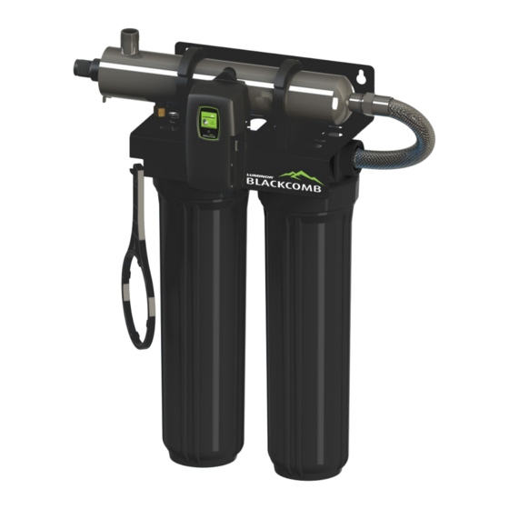
BLACKCOMB
OWNER'S MANUAL
LUMINOR - Rack-Mount Systems
Rated Flow
Sediment
8 gpm
YES (10")
8 gpm
YES (20")
8 gpm
YES (10")
15 gpm
YES (20")
15 gpm
YES (10")
15 gpm
YES (20")
LBH5-Z22
Carbon
NO
NO
YES (20")
NO
YES (20")
YES (20")
Advertisement
Table of Contents

Related Manuals for Luminor BLACKCOMB LB5-Z1


Summary of Contents for Luminor BLACKCOMB LB5-Z1
- Page 1 BLACKCOMB OWNER’S MANUAL Operation & Installation Instructions LB4-Z1 LBH5-Z22 LUMINOR - Rack-Mount Systems System Rated Flow Sediment Carbon LB4-Z1 8 gpm YES (10”) LB5-Z1 LB4-Z2 8 gpm YES (20”) LB5-Z2 LB4-Z12 8 gpm YES (10”) YES (20”) LB5-Z12 LBH4-Z2 15 gpm YES (20”)
- Page 2 This is chemical free process which is simple in its concept and effective in its abilities to inactivate microorganisms present in the water supply. Simple maintenance, continuous disinfection and ultimately safe water, LUMINOR makes it that easy. P a g e...
-
Page 3: Table Of Contents
TABLE OF CONTENTS Safety Considerations ......................4 Before You Begin ........................ 4 Water Quality Parameters ....................5 Assembly ..........................6 System Sizing ........................7 Location ..........................7 Orientation ......................... 8 Installation ......................... 9 System Disinfection ......................12 Cleaning the Quartz Sleeve ....................12 Cleaning the UV Sensor .................... -
Page 4: Safety Considerations
Safety Considerations Although your UV system has been manufactured to the highest safety standards, care must be followed when operating and/or maintaining your system. 1. Before servicing this equipment, disconnect the power cord from the electrical outlet. 2. Energy given off by the UV lamp is harmful to your eyes and skin. NEVER look directly at an illuminated UV lamp without adequate eye protection and always protect your skin from direct exposure to the UV light. -
Page 5: Water Quality Parameters
80% for pre-treatment recommendations) You can have your water tested at a private analytical laboratory or by your local dealer. It is always recommended to install pre-filtration of at least 5 microns prior to a LUMINOR UV disin- fection system. -
Page 6: Assembly
Assembly The BLACKCOMB rack-mount UV system is designed as a do-it-yourself (DIY) system with a single inlet and outlet port. Unpack the system and ensure all the components are included in the box. Your system is shipped with the following components: P a g e... -
Page 7: System Sizing
System Sizing All LUMINOR UV systems are rated for a specific flow rate in water that meets the quality param- eters on page 5. PLEASE NOTE increasing the flow above the system rating or disinfecting water that does not meet the quality parameters will decrease the dose and therefore compromise the microorganism inactivation. -
Page 8: Orientation
PLEASE NOTE: All LUMINOR UV disinfection systems are intended for indoor use only as they should not be exposed to the elements. The controller will require a ground fault circuit inter- rupter (GFCI or GFI) outlet and should be mounted beside or above the reactor. -
Page 9: Installation
Installation Step 1: Once both the orientation and location have been selected, securely fasten the rack to a suitable back- ing. As the rack system is extremely heavy when filled with water, it is imperative that the rack be mounted with suitable fasteners for the particular installation. - Page 10 Figure 5. Cartridge Removal Step 9: Install the UV sensor (BLACKCOMB systems only). Align the flat portion so it faces the gland nut end and matches up with the half metal lip on the sensor port (see Figure 6). Insert the sensor so it is fully seated and hand tighten the sensor nut.
- Page 11 Figure 8a. Standard Output UV Figure 8b. High Output UV Lamp Connection Lamp Connection Step 12: Install the lamp key into the controller (BLACKCOMB , BLACKCOMB systems only). The key always comes packaged with the lamp and sits on the connector. With the key removed from the lamp, orient it so the label is upright and facing you.
-
Page 12: System Disinfection
System Disinfection With a new installation, or any time the UV system is shut down for service, without power, or is inoperative for any other reason, the lines in the home or facility could be contaminated. Use the following steps to fully disinfect the lines throughout the entire home or facility. Step 1: Check for and remove any “dead ends”... -
Page 13: Cleaning The Uv Sensor
Step 10: Dry the sleeve with separate cloth. Step 11: Replace the o-ring and slide the sleeve back into the reactor following steps 7 and 8 from the installation section of the manual. Cleaning the UV Sensor Depending on the water quality, the UV sensor may require periodic cleaning. At a minimum, the UV sensor should be cleaning on an annual basis. -
Page 14: Blackcomb 4.1 Controllers
When the UV lamp is not on or the lamp life has expired, the LED will be illuminated red and an audible buzzer will be sounding. To remedy this condition, the UV lamp must be replaced with a new genuine LUMINOR UV lamp. LBH4 Series... -
Page 15: Blackcomb 5.1 Operational Screens
On systems without the UV monitor, the default screen shows the LUMINOR Home Screen. At any point during operation the user is able to scroll through the LUMINOR Home Screen, Lamp life remaining, QR Code, Contact Info and Maintenance Parts screens by pressing the button located on the front of the controller. -
Page 16: Lamp Countdown Sequence
cycles with red low constant audible audible chirp every audible chirp every UV screen alarm 15 seconds 15 seconds Lamp Countdown Sequence The system counts down the number of days until a lamp change is required. BLACKCOMB BLACKCOMB BLACKCOMB At thirty days remaining, the LED or display screen will change to a yellow caution indicator. At seven days remaining, the system will additionally repeat an audible chirp. -
Page 17: System Service Suggested
A QR code (Quick Response code) is a matrix barcode first designed for the automotive industry. LUMINOR uses the QR code to store a link to a spe- cific page on our website. Users with a camera phone equipped with the correct reader application can scan the image of the QR code and over a wireless network connect to a LUMINOR web page in the phone’s browser. -
Page 18: System Troubleshooting
System Troubleshooting Hard Alarms: The following give a constant audible alarm. If present, the solenoid valve is closed, and the 4-20, remote alarm and Wifi modules transmit the alarm. System Display Problem Resolution Reset lamp protection circuit -unplug unit for 10 seconds. The system has detected Replace the lamp with the a problem with the... -
Page 19: Temperature Management Devices
(minimum 20 minutes at a full boil) prior to consumption. Temperature Management Devices Your LUMINOR BLACKCOMB system is designed to run continuously to ensure optimal disinfection. However, during periods when no water is drawn through the system, the energy from the disinfection process can cause the temperature of the water inside the chamber to rise. -
Page 20: Expansion Modules
Expansion Modules BLACKCOMB and BLACKCOMB controllers incorporate an “Infinite Expandability Port” (IEP) which allows for expansion to the UV sensor and all other modules. Each module (including the sensor) comes with both a male and female connection. Connect any device to the controller and all subsequent devices are then connected into the female end of last device added in a “daisy chain”... -
Page 21: Blackcomb Rack-Mount Uv System Specifications
BLACKCOMB Rack-Mount UV System Specifications LUMINOR EQUIPMENT SPECIFICATIONS RACK-MOUNT UV SYSTEMS LB4-Z1 LB4-Z2 LB4-Z12 LBH4-Z2 LBH4-Z12 LBH4-Z22 MODEL LB5-Z1 LB5-Z2 LB5-Z12 LBH5-Z2 LBH5-Z12 LBH5-Z22 8.0 gpm 15.0 gpm Flow Rate 30.3 lpm 56.8 lpm (@30mJ/cm 1.82 m 3.4 m 5.6 gpm... -
Page 22: Limited Warranty Statement
LUMINOR are subject to the warranty provided by the manufacturer of said products and not by LUMINOR’s warranty. LUMINOR will not be liable for damage or wear to products caused by abnormal operating conditions, accident, abuse, misuse, unauthorized al- teration or repair, or if the product was not installed in accordance with LUMINOR’s printed... -
Page 23: Warranty Registration
837-3801 (519-837-3800 outside of the US or Canada) to obtain a Warranty Return Authoriza- tion. You will then need to return the product through the LUMINOR Dealer or Distributor where the product was originally purchased, together with proof of purchase and installation date, failure date, and supporting installation data. - Page 24 illuminating technologies for life 80 Southgate Drive, Unit 4 Guelph, Ontario, CANADA N1G 4P5 P: 519-837-3800 TF: 855-837-3801 F: 519-837-3808 info@luminoruv.com www.luminoruv.com PN#910114 Version Date: 12-2020...
Need help?
Do you have a question about the BLACKCOMB LB5-Z1 and is the answer not in the manual?
Questions and answers