Table of Contents
Advertisement
Quick Links
Technical Reference Guide
Product Overview
Describes features and general specifications for the product.
Setup
Describes setup and installation of the product.
Application Development Information
Describes how to control the scanner and necessary information
when you develop applications.
Handling
Describes how to handle the product.
Appendix
Describes the interface and character code tables.
M00046102
Rev. C
Advertisement
Table of Contents

Related Manuals for Epson TM-S2000 Series


Summary of Contents for Epson TM-S2000 Series
- Page 1 Technical Reference Guide Product Overview Describes features and general specifications for the product. Setup Describes setup and installation of the product. Application Development Information Describes how to control the scanner and necessary information when you develop applications. Handling Describes how to handle the product. Appendix Describes the interface and character code tables.
- Page 2 • Neither is any liability assumed for damages resulting from the use of the information contained herein. • Neither Seiko Epson Corporation nor its affiliates shall be liable to the purchaser of this product or third parties for damages, losses, costs, or expenses incurred by the purchaser or third parties as a result of: accident, misuse, or abuse of this product or unauthorized modifications, repairs, or alterations to this product, or (excluding the U.S.) failure to strictly comply with Seiko Epson Corporation’s operating...
-
Page 3: For Safety
For Safety Key to Symbols The symbols in this manual are identified by their level of importance, as defined below. Read the following carefully before handling the product. You must follow warnings carefully to avoid serious bodily injury. WARNING Provides information that must be observed to prevent damage to the equipment or loss of data. -
Page 4: Warnings
Shut down your equipment immediately if it produces smoke, a strange odor, or unusual noise. Continued use may lead to fire. Immediately unplug the equipment and contact your dealer or a Seiko Epson service center for advice. Never attempt to repair this product yourself. Improper repair work can be dangerous. -
Page 5: Cautions
Cautions Do not connect cables in ways other than those mentioned in this manual. Different connections may cause equipment damage or fire. Be sure to set this equipment on a firm, stable, horizontal surface. CAUTION The product may break or cause injury if it falls. ... -
Page 6: About This Manual
About this Manual Aim of the Manual This manual was created to provide information on development and design of scanner applications for developers. Manual Content The manual is made up of the following sections: Chapter 1 Product Overview Chapter 2 Setup Chapter 3 Application Development Information... -
Page 7: Table Of Contents
Contents ■ For Safety..........................3 Key to Symbols ............................3 Warnings ..............................4 Cautions..............................5 ■ Restriction of Use........................5 ■ About this Manual ........................6 Aim of the Manual..........................6 Manual Content ............................ 6 ■ Contents ..........................7 Product Overview ................10 ■ Features ..........................10 ■... - Page 8 Scanner Specifications ........................35 MSR (Factory Option)...........................36 Paper Specifications ..........................37 Printable Area............................38 Scannable Area ...........................39 MICR Readable Area ..........................41 Area for Electric Endorsement ......................41 Environmental Conditions ........................42 Reliability..............................42 External Dimensions and Mass ......................43 Setup .....................45 ■ Flow of Setup ........................45 ■...
- Page 9 Opening the Scanner Cover......................60 ■ Processing Cut Sheet Paper ....................61 Flow of Single Pass Processing......................61 Important Notes on Processing Cut Sheet Paper ................61 Inserting Cut Sheet Paper ........................62 Ejecting Cut Sheet Paper ........................63 ■ Scanning ID Cards......................64 ■...
-
Page 10: Product Overview
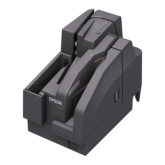
Product Overview This chapter describes features and specifications of the TM-S2000MJ. Features This compact, full-scale, up-grade hybrid product integrates functions of printing, check computerization, personal ID image reading, and magnetic card stripe reading (optional) required mainly for reception work at banks. The main features are as follows. -
Page 11: Product Configuration
2 pockets Installed Installed Not installed Not installed dpm: documents per minute Color EDG (Epson Dark Gray) Attachments • USB cable • 2 dedicated ink cartridges (Model: SJIC18(K)) • AC cable* • AC adapter • Setup Guide • User’s Manual... -
Page 12: Part Names And Functions
Part Names and Functions (See "Control Panel" on page 13.) Control panel Two-pocket model Sub pocket Main pocket MICR cover Connectors (See "Connectors" on page 15.) Pocket guide Pocket guide MICR cover open lever ASF guide Power button MSR (factory option)-equipped model Scanner cover Scanner cover open lever Ink cartridge cover... -
Page 13: Power Button
Chapter 1 Product Overview Power Button Turns the product on or off. Be sure not to turn off the product or open the covers while the Power LED is flashing. Control Panel (Power) LED Error LED Document LED ID Card LED Ink LED Cleaning button Power LED (Green) - Page 14 Document LED (Green) • Lights when the product is ready to process cut sheet paper in the ASF or while the product is processing cut sheet paper. • Flashes when the product is waiting for cut sheet paper insertion. • Goes out except for the cases above. ID Card LED (Green) •...
-
Page 15: Connectors
Chapter 1 Product Overview Connectors All cables are connected to the connector panel on the lower rear of the product. ➀ • Power supply connector ( Connects the power supply unit. ➁ • USB connector (Type B) ( Connects the product with the host computer. ➂... -
Page 16: Offline
Offline The TM-S2000MJ automatically goes offline under the following conditions: • During initialization after: Power on (including resetting with the interface) Removal of error causes • When any of the following covers are opened: Ink cartridge cover MICR cover Scanner cover •... -
Page 17: Processing Modes For Cut Sheet Paper
Chapter 1 Product Overview Processing Modes for Cut Sheet Paper The TM-S2000MJ has the following processing modes that are selectable with the driver in accordance with how you want to use the product with cut sheet paper. • High-speed mode •... - Page 18 When ejecting into the sub pocket (only for two-pocket models) When documents are sorted into the two ejection pockets, a document is fed backward to the pocket switching position and then ejected into a pocket if the ejection pocket is required to be switched and the document is long.
-
Page 19: Confirmation Mode
Chapter 1 Product Overview Confirmation Mode This mode selects pockets and specifies whether to continue processing according to commands from the application for each scan. Confirmation mode with overlap The product starts feeding the next document while ejecting the current document into a pocket. <First document>... - Page 20 When ejecting into the sub pocket (only for two-pocket models) When the two-pocket model receives a command to eject a document into a pocket, the processing slows down because it feeds the document backward to the pocket switching position and ejects it into a pocket. <First document>...
- Page 21 Chapter 1 Product Overview Confirmation mode without overlap The product starts feeding the next cut sheet paper after the current cut sheet paper has been stored completely into the pocket. <First document> Fed from the ASF Check for double feeding MICR reading Ink jet printing Capturing image on both sides...
- Page 22 When ejecting into the sub pocket (only for two-pocket models) When the two-pocket model receives a command to eject the document into the sub pocket, the processing slows down because it feeds the cut sheet paper backward to the pocket switching position and ejects it into the sub pocket.
-
Page 23: Selectable Functions For Processing Cut Sheet
Chapter 1 Product Overview Selectable Functions for Processing Cut Sheet The TM-S2000MJ has the following functions that are selectable with the driver in accordance with how you want to use the product with cut sheet paper. Settings with an application are also available for the pocket ejection and processing continuance in the confirmation mode. - Page 24 Functions and Judgment Conditions to be Selected in Each Processing Mode: Processing Judgment Selectable Functions Modes Judged by F/W When judgments are made from the following conditions only. • Detecting double feeding • Detecting incorrect insertion • (Check paper) • Detecting magnetic waveform •...
-
Page 25: Error Status
Chapter 1 Product Overview Error Status When an error occurs, the printer stops operating, goes offline, and the Error LED flashes. There are three possible error types: automatically recoverable errors, recoverable errors, and unrecoverable errors. Automatically Recoverable Errors Printing is no longer possible when automatically recoverable errors occur. They can be recovered easily, as described below. -
Page 26: Recoverable Errors
Recoverable Errors Processing is no longer possible when recoverable errors occur. They can be recovered easily by sending an error recovery command from the driver after eliminating the cause of the error. Error LED flash code Error Error description Recovery measure Approx.320 ms Mechanism The home position of the... -
Page 27: Unrecoverable Errors
Chapter 1 Product Overview Unrecoverable Errors Processing is no longer possible when unrecoverable errors occur. The scanner must be repaired. Turn off the power immediately when unrecoverable errors occur. CAUTION Error LED flash code Error Error description Approx. 320 ms Drive circuit error ·... -
Page 28: Nv Memory (Non-Volatile Memory)
NV Memory (Non-Volatile Memory) The printer's NV memory stores data even after the printer power is turned off. NV memory contains the following memory areas for the user: • NV graphics memory • User NV memory • Memory switches • User-defined page •... -
Page 29: User-Defined Page
Chapter 1 Product Overview User-defined Page You can store character data in the user-defined page (character code table: page 255) so that you can also print characters not resident in the printer. Maintenance Counter With this function, printer information, such as the number of head shots for ink jet , the count of ASF feeding, and printer operation time after the printer starts working, is automatically stored in NV memory. -
Page 30: Maintenance Counter
Maintenance Counter The TM-S2000MJ has the maintenance counter to get the following counts. Counter Counter type Unit Number of head shots for ink jet (Column A) Resettable/Cumulative 1000 shots Number of head shots for ink jet (Column B) Resettable/Cumulative 1000 shots Count of pump motor operations Resettable/Cumulative Count... -
Page 31: Product Specifications
Chapter 1 Product Overview Product Specifications ASF paper supply Number of sheets that can be loaded: 100 sheets or fewer (when the paper thickness is 0.13 mm or less). However, the total thickness must be 13 mm or less including warps. Pocket storage One-pocket 100 sheets or fewer (when the paper thickness is 0.13 mm or... - Page 32 Ink cartridge Exclusive ink cartridge: SJIC18(K) Color of ink: Black Power supply Specified AC adapter Operating voltage DC24V ± 7% * USB (Type A) connector is a factory option. The specified processing speed is not achievable when using USB Full-Speed.
-
Page 33: Printing Specifications
Chapter 1 Product Overview Printing Specifications Printing method Line ink jet printing with ink jet head Nozzle arrangement 360 nozzles in 2 lines 180 180 dpi Dot density Printing direction Fixed stroke control Print height 50.80 mm {2.00 in} Printable lines Font A 12 lines maximum... -
Page 34: Character Specifications
Character Specifications Number of characters Alphanumeric characters 95 characters 128 characters 11 pages (including user- Extended graphics defined page) International characters 37 characters 12 24 (including 2-dot horizontal spacing) Character structure Font A 9 17 (including 2-dot horizontal spacing) Font B Character size (W ... -
Page 35: Scanner Specifications
Chapter 1 Product Overview Scanner Specifications Image Scanner CIS (Contact Image Sensor) Resolution (H W) 300 300 dpi, 240 240 dpi, 200 200 dpi, Cut sheet paper 120 120 dpi, 100 100 dpi 600 600 dpi, 300 300 dpi, 200 200 dpi ID cards Graduation Binary (black and white)*... -
Page 36: Msr (Factory Option)
ID card Type ISO/IEC7810 compliant (without embossed effect) Size (H W) 53.92 to 54.18 mm {2.12 to 2.13 in} 85.47 to 85.90 mm {3.36 to 3.38 in} Thickness 0.5 to 0.84 mm {0.02 to 2.13 in} Warpage 2 mm maximum (ISO/IEC7810) dpi: dots per inch (25.4 mm) Binary is supported by cut sheet paper only. -
Page 37: Paper Specifications
Chapter 1 Product Overview Paper Specifications Type Normal paper (single-ply only) Size (H W) 60 to 120 mm {2.36 to 4.72 in} 120 to 235 mm {4.72 to 9.25 in} Thickness 0.075 to 0.2 mm {0.003 to 0.008 in} (single-ply only) Weight 60 to 120 g/m {16 to 32 lb}... -
Page 38: Printable Area
Printable Area When the printing position is set from the top of the paper 50.8 mm 18 mm Check insertion direction 10 mm 10 mm When the printing position is set from the end of the paper 50.8 mm 18 mm Check insertion direction 60.8 mm 10 mm... -
Page 39: Scannable Area
Chapter 1 Product Overview Scannable Area Cut sheet paper Image scanning may not be possible in the area a and b in the figures below. The quality of the scanned image may be decreased in the area c. Image width: Max. 255.0 mm No. - Page 40 ID card 10 mm 10 mm Insertion direction (Backward feeding) Paper path for check Max 116 mm Scanning direction...
-
Page 41: Micr Readable Area
Chapter 1 Product Overview MICR Readable Area MICR read width: Max. 241 mm Reading starting position of MICR: 3 mm from the paper edge Readable width of paper: Max. 235 mm Readable MICR width: Max. 225 mm Max. 12.7 mm Paper inserting direction Area for Electric Endorsement 120 ~ 235... -
Page 42: Environmental Conditions
Environmental Conditions Temperature/ Operating 10 ~ 35°C {50 ~ 95°F}, 20 ~ 80% RH without condensation (See humidity the operating temperature and humidity range below.) Storage -20 ~ 60°C {-4 ~ 140°F}, 5 ~ 85% RH without condensation (120 hours or less at -20 {-4°F} or 60°C {140°F}) (Factory packing) Maximum 70°C {158°F} (This temperature must never be exceeded... -
Page 43: External Dimensions And Mass
Chapter 1 Product Overview External Dimensions and Mass The values below are when the pocket guide is fully pulled out. One-pocket model Height Approximately 177.0 mm {6.97 in} Width Approximately 142.0 mm {5.59 in} Depth Approximately 374.8 mm {14.76 in} Mass Approximately 4.5kg {9.92 lb} [Unit: mm]... - Page 44 Two-pocket model Height Approximately 177.0 mm {6.97 in} Width Approximately 167.0 mm {6.57 in} Depth Approximately 409.8 mm {16.13 in} Mass Approximately 4.5 kg {9.92 lb} [Unit: mm]...
-
Page 45: Setup
Chapter 2 Setup Setup This chapter describes setup and installation of the product. Flow of Setup This chapter consists of the following sections along with the setup flow of the product. 1. Installing the Product (page 46) 2. Connecting the Product to the Host Computer (page 47) 3. -
Page 46: Installing The Product
Installing the Product Important Notes on Installation • Install the product horizontally. • Make sure that the product is not subjected to any impact or vibration. • Do not place the product near any magnetic fields to avoid decreasing the MICR recognition rate. -
Page 47: Connecting The Product To The Host Computer
Chapter 2 Setup Connecting the Product to the Host Computer Follow the steps below to connect the product to a host computer. Be sure to install the driver before connecting the product to the host computer. Be sure to use the USB cable that is included with the product. Connect the USB cable to the USB (Type B) connector. -
Page 48: Connecting The Power Supply Unit
Connecting the Power Supply Unit Follow the steps below to connect the power supply unit to the product. Be sure to use the specified AC adapter only. Connection to an improper power source may cause fire or shock. Should a fault ever occur in the AC adapter immediately turn off the power to the WARNING product and remove the power supply cable from the wall socket. -
Page 49: Installing And Replacing The Ink Cartridge
Chapter 2 Setup Installing and Replacing the Ink Cartridge Follow the steps below to install the ink cartridge into the product for the first time or replace it with a new one. Do not open the ink cartridge until you are ready to install it. ... - Page 50 If there is a used ink cartridge, remove it by pulling up the tab on the top of the cartridge while holding the product. Remove a new ink cartridge from its package. Install the ink cartridge in the correct direction, and push it until it clicks in place.
-
Page 51: Setting The Memory Switches
Chapter 2 Setup Setting the Memory Switches With the memory switches function, which are software settings for the printer, you can set the various functions. Use TM-S2000 Utility to set the memory switches. For detailed information about the TM-S2000 Utility, see the TM-S2000 Utility User’s Manual. - Page 52 Validation settings Paper feed direction Top margin (dots) Left margin 50.8 mm (dots) Print Area 18 mm 10 mm 10 mm • Top margin (initial setting: 0) • Left margin (initial setting: 0) Slip settings Paper feed direction Top margin (dots) Left margin (dots) 50.8 mm...
-
Page 53: Application Development Information
Chapter 3 Application Development Information Application Development Information This chapter describes software and gives information useful for printer application development. Software Operating Environment Minimum Specification • CPU: At least a Pentium 4, 2.0 GHz or the equivalent • Memory: At least 512 MB or above the minimum operating system requirement •... -
Page 54: Software For Windows
Software for Windows Software Description TM-S2000 Driver Use this API (Application Program Interface) to fully use functions of the TM-S2000MJ, such as the scanner function, endorsement printing function, cut sheet paper printing function, and to monitor the status of the TM-S2000MJ. Programming can be done in Visual C++, Basic, or other programming languages. -
Page 55: Software For Linux
How to Get Drivers, Utilities, and Manuals You can obtain drivers, utilities, and manuals from one of the following URLs. For customers in North America, go to the following web site: http://www.epson.com/support/ For customers in other countries, go to the following web site: http://download.epson-biz.com/?service=pos... -
Page 56: Setting/Checking Modes
Setting/Checking Modes Besides the ordinary print mode, the printer has the following modes to set or check settings of the printer. • Self-test Mode • NV Graphics Print Mode Self-test Mode In the self-test mode, the printer prints the current status of the printer and resident characters as a test print. -
Page 57: Nv Graphics Print Mode
Chapter 3 Application Development Information NV Graphics Print Mode You can confirm the following information by running NV graphics print mode: • Capacity of the NV graphics • Used amount of the NV graphics • Unused capacity of the NV graphics •... -
Page 58: Handling
Handling This chapter describes basic handling of the scanner. Turning On/Off the Product Power button Turning On To turn on the product, press the power button on the front side of the product. Turning Off When turning off the product, make sure the AC cable is connected to the product and a wall socket, and always use the power button. -
Page 59: Opening Covers
Chapter 4 Handling Opening Covers Do not open the covers while processing is in progress. Opening the Ink Cartridge Cover Put your finger under the left side of the ink cartridge cover and pull it up to open it. Opening the MICR Cover Pull the MICR cover open lever and pull the MICR cover outward to open it. -
Page 60: Opening The Scanner Cover
Opening the Scanner Cover Pull the scanner cover open lever and pull the scanner cover outward to open it. -
Page 61: Processing Cut Sheet Paper
Chapter 4 Handling Processing Cut Sheet Paper The TM-S2000MJ is capable of performing the following actions on cut sheet paper in a single pass. Flow of Single Pass Processing ➀ Auto sheet feeder (ASF) section feeds the cut sheet paper. ( ➁... -
Page 62: Inserting Cut Sheet Paper
Inserting Cut Sheet Paper You can put up to 100 sheets of cut sheet paper in the ASF to be fed automatically. Pull out the ASF guide and the pocket guide appropriately for the size of the cut sheet paper to be set. Set the cut sheet paper in the ASF with the edges aligned to the paper setting mark on the right side of the ink cartridge cover. -
Page 63: Ejecting Cut Sheet Paper
Chapter 4 Handling Ejecting Cut Sheet Paper Remove the cut sheet paper when it is ejected. To prevent a paper jam, do not leave more than 100 sheets in the pocket (for two-pocket models, 100 sheets in the main pocket and 50 sheets in the sub pocket) while processing cut sheet paper. -
Page 64: Scanning Id Cards
Scanning ID Cards Follow the steps below to scan both sides of an ID card. Use an ID card that meets the specifications. (See "Paper Specifications" on page 37.) Make sure that the ID card is flat and does not have excessive bending, cracks, folds, or embossing. -
Page 65: Reading Magnetic Stripe Cards
Chapter 4 Handling Reading Magnetic Stripe Cards If your product has a MSR unit, you can read the magnetic stripe on the card. Use a magnetic stripe card that meets the specification. (See "MSR (Factory Option)" on page 36.) To read the magnetic stripe card, check the insertion direction with the arrow on the card, and swipe it through the slit downward or upward with the magnetic stripe on the card facing inside and down. -
Page 66: Cleaning
• KIC Team, Inc. “Waffletechnology cleaning card” (CS1B15WS) • KIC Team, Inc. "Epson Check Scanner Cleaning Kit" (Model: KWEPS-KCS2) Use a cleaning sheet only one time; then discard it. It is recommended to clean the MICR head once per week or once every 2,000 sheets for good reading results. -
Page 67: Cleaning The Scanner
Chapter 4 Handling Cleaning the Scanner If the glass of the scanner gets soiled from ink or paper dust, the quality of scanned data may deteriorate. Clean the glass every 6 months or every 100,000 passes by following the steps below. ... -
Page 68: Cleaning The Product Case
Cleaning the Product Case Be sure to turn off the product, and wipe the dirt off the product case with a dry cloth or a damp cloth. Never clean the product with alcohol, benzine, thinner, or other such solvents. Doing so may damage or break the parts made of plastic and rubber. CAUTION... -
Page 69: Troubleshooting
Chapter 4 Handling Troubleshooting Error LED Is On or Flashing "Error Status" on page Paper or ID Card Is Jammed When cut sheet paper is jammed Open the MICR cover or scanner cover to remove the jammed paper in the paper path. "Opening the MICR Cover"... -
Page 70: Preparing For Transport
Preparing for Transport Follow the steps below to transport the product. Keep the product upright and horizontal during transportation. Install the transportation cartridge If transporting a product for which the initial ink filling has been done, install the transportation cartridge and transport it. Failure to do so may cause ink leaks. Transportation cartridge: TRANSPORTATION CARTRIDGE, SJIC18, UNIT Turn on the product. -
Page 71: Appendix
Appendix Appendix Specifications of USB Interface USB Interface (Type B) Outline • High-speed transmission at 480 Mbps [bps: bits per second] • Plug & Play, Hot Insertion & Removal USB transmission specifications Overall specifications According to USB 2.0 specifications Transmission speed USB High-Speed (480 Mbps) USB Full-Speed (12 Mbps) Transmission method... -
Page 72: Character Code Tables
Character Code Tables The character code tables show only character configurations. They do not show the actual print pattern. “SP” in the table shows a space. Common to All Pages When the international character set (See "International Character Sets" on page 84.) is USA: "... -
Page 73: Pc437: Usa, Standard Europe]
Appendix Page 0 [PC437: USA, Standard Europe] Ç É á ░ └ ╨ α ≡ í ü æ ▒ ┴ ╤ β ± Γ é Æ ó ▓ ┬ ╥ ≥ â ô ú │ ├ ╙ π ≤ ä ö... -
Page 74: Katakana)
Page 1 (Katakana) ┴ ═ ┬ ╞ ┤ ╪ ├ ╡ ¯ ─ │ │ ┌ ♠ ┐ ♥ └ ♦ ┘ ♣ ● ○ ▓ ┼... -
Page 75: Pc850: Multilingual)
Appendix Page 2 (PC850: Multilingual) Ç É á ░ └ ð Ó í ü æ ▒ ┴ Ð β ± é Æ ó ▓ ┬ Ê Ô â ô ú │ ├ Ë Ò ¾ ä ö ñ ┤ ─ È... -
Page 76: Pc860: Portuguese)
Page 3 (PC860: Portuguese) Ç É á ░ └ ╨ α ≡ í ü À ▒ ┴ ╤ β ± Γ é È ó ▓ ┬ ╥ ≥ â ô ú │ ├ ╙ π ≤ ã õ ñ ┤ ─... -
Page 77: Pc863: Canadian-French)
Appendix Page 4 (PC863: Canadian-French) Ç É ¦ ░ └ ╨ α ≡ ü È ´ ▒ ┴ ╤ β ± Γ é Ê ó ▓ ┬ ╥ ≥ â ô ú │ ├ ╙ π ≤ Â Ë ¨ ┤... -
Page 78: Pc865: Nordic)
Page 5 (PC865: Nordic) Ç É á ░ └ ╨ α ≡ í ü æ ▒ ┴ ╤ β ± Γ é Æ ó ▓ ┬ ╥ ≥ â ô ú │ ├ ╙ π ≤ ä ö ñ ┤ ─... -
Page 79: Wpc1252)
Appendix Page 16 (WPC1252) € ° À Ð à ð ‘ ¡ ± Á Ñ á ñ ‚ ’ ¢ ² Â Ò â ò ƒ “ £ ³ Ã Ó ã ó ´ „ ” ¤ Ä Ô ä ô... -
Page 80: Pc866: Cyrillic #2)
Page 17 (PC866: Cyrillic #2) А Р а ░ └ ╨ р Ё Б С б ▒ ┴ ╤ с ё В Т в ▓ ┬ ╥ т Є Г г У │ ├ ╙ у є Ї Д Ф д... -
Page 81: Pc852: Latin2)
Appendix Page 18 (PC852: Latin2) Ç É á ░ └ đ Ó í ü Ĺ ▒ ┴ Ð β ˝ ĺ é ó ▓ ┬ Ď Ô ˛ â ô ú │ ├ Ë Ń ˇ ä ö Ą ┤ ─... -
Page 82: Pc858: Euro)
Page 19 (PC858: Euro) Ç É á ░ └ ð Ó í ü æ ▒ ┴ Ð β ± é Æ ó ▓ ┬ Ê Ô â ô ú │ ├ Ë Ò ¾ ä ö ñ ┤ ─ È õ... -
Page 83: User-Defined Page)
Appendix Page 255 (User-Defined Page) -
Page 84: International Character Sets
International Character Sets ASCII code (Hex) Country ¥ France à ° ç § é ù è ¨ Germany § Ä Ö Ü ä ö ü β U.K. £ ¥ Denmark I Æ Ø Å æ ø å Sweden ¤ É Ä...
Need help?
Do you have a question about the TM-S2000 Series and is the answer not in the manual?
Questions and answers