Table of Contents
Advertisement
Quick Links
Advertisement
Table of Contents

Related Manuals for Intermec RM91501X04


Summary of Contents for Intermec RM91501X04
- Page 1 Quick Start Guide PRELIMINARY EDITION 20 June 02 ITRF91501 Reader...
-
Page 2: Packing List
Check to ensure that you receive these items: Intermec ITRF91501 MHz Reader Model Number ITRF91501 (part number country dependent) Product Warranty Card... -
Page 3: Host Communication
ITRF91501 Reader Quick Start Guide Host Communication Host communication comes through the 9-pin female D-sub connector. Both RS-232 and RS-422 standards are supported as ordered from the factory or service center Table 1-1 RS-232 Connections Pin Number Definition Serial Data from the Fixed Reader to the host Serial Data to the Fixed Reader from the host Ground CTS (Clear to Send) to the Fixed Reader from the... -
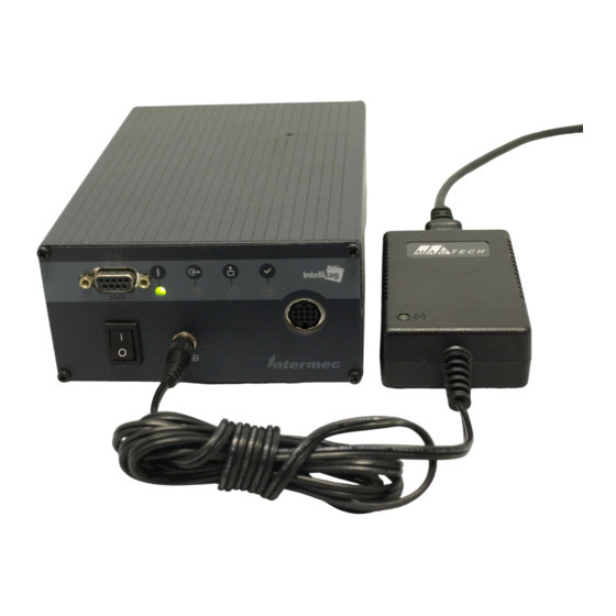
Page 4: Power Requirements
ITRF91501 Reader Quick Start Guide Power Requirements Power comes in from 8 to 10 volts DC. The Fixed Reader uses less than 2 amps. Intermec supplies 9 volts DC at 2.4 amps from Intermec power supply, p/n: 351-066-001. User I/O... - Page 5 ITRF91501 Reader Quick Start Guide climb higher as the sink current increases. There is no protec- tion on this. You need to ensure that their load won’t require the reader to sink more than 50 mA. Input signals should be 0 to +1.5 volt for a low input and +3.5 to +5 volts for a high input.
- Page 6 ITRF91501 Reader Quick Start Guide Front view of the antenna 1. Review the locations where the Reader products need in- tegrated. Ensure that you have careful considered the safe distances for product placement for workers and any other personnel that may get in the RF path. 2 .
- Page 7 ITRF91501 Reader Quick Start Guide The following illustrations are a couple of examples for Reader installations. EXAMPLE 1: Shipping Dock Door, showing two antennas at each shipping door. Two antennas in a crossing pattern provide angular diversity to improve read capability when tag orientation is unknown.
- Page 8 ITRF91501 Reader Quick Start Guide EXAMPLE 2: Two Product Line Conveyers, showing two antennas on each line. Two antennas in a crossing pattern provide angular diversity to improve read capability when tag orientation is unknown. The frames for these stations are PVC tubing with RF reflec- tive Mylar liner X2.
- Page 9 ITRF91501 Reader Quick Start Guide Connecting the Antenna to the Reader 1. Connect antenna cable to a port. 2. Connect a reverse-sex SMA terminator (Intermec p/n 345-004-001) to any port that does not have an antenna attached. " NOTE: Each port must have either an antenna or a termina- tor connected.
- Page 10 ITRF91501 Reader Quick Start Guide 5. Review the front panel LEDs to become familiar with the status indications you will receive from your Reader. LEDs position (left to right) 0, 1, 2, 3 Auxilary I/O connector RS-232 or RS-422 port Power supply jack I (ON) O (OFF) switch Meaning...
-
Page 11: Troubleshooting
425--356--1799 (elsewhere). Diagnostic PENNRFID.EXE Utility Should your Reader fail to read tags, download the test utility from the Intermec web site (http://www.intermec.com). This utility PENNRFID.EXE is a self-extracting zip file that includes installation instructions and a test utility to check the operation of the Reader on a laptop or desktop computer. -
Page 12: Performance Specifications
ITRF91501 Reader Quick Start Guide Performance Specifications Dependent upon operating conditions and demands expected. If used in a normal office environment with good read conditions, you could expect to read up to six tags per second. Tags located too far away or in poor locations with respect to interfering objects provides poor results. - Page 13 ITRF91501 Reader Quick Start Guide Table 1-5 (Continued) ITRF91501 Reader Specification Criteria Range Vibration 1.0 GRMS. 10 to 500 Hz in three axis Channel switching 30 uS (TX on a channel, to TX on any other channel) Frequency stability ±100 PPM Transmitter power output 700 mW (min.), 800 mW (typical), 1000 mW(max.), @ connector.
- Page 14 ITRF91501 Reader Quick Start Guide www.intermec.com IITRF91501 Reader, Quick Start Guide-March, 2002 *962054052* 962054052 REV A...
Need help?
Do you have a question about the RM91501X04 and is the answer not in the manual?
Questions and answers