
Related Manuals for Billy Goat BC2600EU Hydro Series


Summary of Contents for Billy Goat BC2600EU Hydro Series
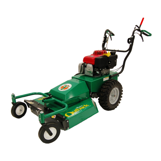
- Page 1 BC26EU HYDRO-DRIVE Owner’s Manual BC2600EU Hydro Series Brush Cutter Owner’s Manual Beginning Serial #: 100515001 Original Instructions IMPORTANT- READ CAREFULLY BEFORE USE AND KEEP FOR FUTURE REFERENCE Part No 501606 501606_C_HI...
-
Page 2: Table Of Contents
BC26EU HYDRO-DRIVE Owner’s Manual CONTENTS SPECIFICATIONS ______________________________________________ 3 INSTRUCTION LABELS __________________________________________ 4 ASSEMBLY INSTRUCTIONS ____________________________________ 5-6 OPERATION _________________________________________________ 7-8 MAINTENANCE AND BATTERY MAINTENANCE__________________ 9-12 TROUBLESHOOTING ___________________________________________13 ILLUSTRATED PARTS LIST ___________________________________ 14-21 Part No 501606 501606_C_HI... -
Page 3: Specifications
BC26EU HYDRO-DRIVE Owner’s Manual BC2600EU SERIES SPECIFICATIONS BC2600ICHEU BC2600HHEU Engine Type Briggs and Stratton Honda GXV390 Model Number 219972 0151 F1 GXV390UT2 DABG Displacement 344 cc 390 cc Fuel Capacity 3.0 qt (2.80 L) 3.0 qt (2.80 L) Oil Capacity 1.5 qt (1.4L) 1.2 qt (1.1L) Unit Weight... -
Page 4: Instruction Labels
INSTRUCTION LABELS ® The labels shown below were installed on your BILLY GOAT Euro Hydro-Drive Brush Cutter. If any labels are damaged or missing, replace them before operating this equipment. Item numbers from the Illustrated Parts List and part numbers are provided for convenience in ordering replacement labels. -
Page 5: Assembly Instructions
BC26EU HYDRO-DRIVE Owner’s Manual Brush Cutter Assembly Drawing Part No 501606 501606_C_HI... - Page 6 PACKING CHECKLIST ® Your BILLY GOAT BCHydro-Drive Brush Cutter was shipped in one carton, completely assembled except for the upper handle assembly and the front caster bracket mount. Mounting hardware for the handle and caster bracket mount can be found in the parts bag.
-
Page 7: Operation
BC26EU HYDRO-DRIVE Owner’s Manual OPERATION OPERATOR CONTROLS The operator’s station is at the rear of the machine between the handlebars. The operator should STAND in a position to allow both handlebars to be grasped firmly and which allows sufficient leverage to steer the machine. Operator’s controls are shown below. - Page 8 BC26EU HYDRO-DRIVE Owner’s Manual CUTTING OPERATION 1. Press blade clutch handle down (See Fig. 4) to engage blade. Allow blade to spin up to normal operating speed. 2. Pull Forward (See Fig. 5) or Reverse Drive lever (See Fig. 6) up to engage transaxle in desired direction.
-
Page 9: Maintenance And Battery Maintenance
CLEANING ® Your BILLY GOAT Brush Cutter should be cleaned periodically to ensure optimum performance and service life. Clogs and debris should be removed from the blade area and debris should be removed from the engine cooling fins. A garden hose or pressure washer may be used for cleaning. - Page 10 If the lock nut is removed and replaced more than once, it should be replaced with a new lock nut (P/N 8160009). When replacing the blade use BILLY GOAT Industries PN 501224 only. 6. Attach new blade with new blade bolt (item 23), and new friction washer (item 39) removed earlier included with your new blade.
- Page 11 BC26EU HYDRO-DRIVE Owner’s Manual NOTE: See Fig 11 for proper belt routing. TRANSAXLE DRIVE BELT REMOVAL AND REPLACEMENT DISCONNECT spark plug wire before servicing unit. 1. Disconnect spark plug wire. 2. Lift and support the rear of the unit to allow access to the underside. 3.
- Page 12 BC26EU HYDRO-DRIVE Owner’s Manual TRANSAXLE DRIVE ADJUSTMENT DISCONNECT spark plug wire before servicing unit. 1. Disconnect spark plug wire. 2. Adjustments to cable tension are made at the barrel entering the Drive Control Levers. INCREASE 3. Adjust cable tension by tightening or loosening cable adjustment barrel on rear of engine base (see below).
-
Page 13: Troubleshooting
BC26EU HYDRO-DRIVE Owner’s Manual TROUBLESHOOTING Problem Possible Cause Corrective Action Engine will not start Throttle is set to Slow/Stop position. Move throttle to fast position. Out of gasoline. Fill gas tank. Old or contaminated gasoline. Drain gas tank and fill with fresh gasoline. -
Page 14: Illustrated Parts List
BC26EU HYDRO-DRIVE Owner’s Manual BC26EU HYDRO-DRIVE DECK PARTS DRAWING Part No 501606 501606_C_HI... - Page 15 BC26EU HYDRO-DRIVE Owner’s Manual BC26EU HYDRO-DRIVE DECK PARTS LIST ITEM BC2600HHEU BC2600ICHEU DESCRIPTION Part No Part No SCREWCAP 3/8-24 X 1” HCS GR. 8 900154 900154 501224 501224 BLADE 26” FLAT BC26 WASHER DECK RETAINNG 501214 501214 LABEL BADGING BC26 HYDRO 501500 501500 LABEL DANGER...
- Page 16 BC26EU HYDRO-DRIVE Owner’s Manual BC26EU HYDRO-DRIVE ENGINE PARTS DRAWING Part No 501606 501606_C_HI...
- Page 17 BC26EU HYDRO-DRIVE Owner’s Manual BC26EU HYDRO-DRIVE ENGINE PARTS LIST BC2600HHEU BC2600ICHEU ITEM DESCRIPTION Part No Part No SCREWCAP 3/8-24 X 1” HCS GR. 8 900154 900154 WASHER DECK RETAINING 501214 501214 NUT LOCK 5/16”-18 ZP 8160002 8160002 ENGINE BASE WA W/LABELS 501603 501603 SCREW SELT TAP 1/4-20 X 5/8”...
- Page 18 BC26EU HYDRO-DRIVE Owner’s Manual BC26EU HYDRO-DRIVE HANDLE PARTS LIST Part No 501606 501606_C_HI...
- Page 19 BC26EU HYDRO-DRIVE Owner’s Manual BC26EU HYDRO-DRIVE HANDLE PARTS LIST ITEM BC2600HHEU BC2600ICHEU DESCRIPTION Part No Part No NUT LOCK 5/16-18 ZP 8160002 8160002 NUT LOCK 3/8-16 HEX 8160003 8160003 HANDLE LOWER LEFT 501400 501400 BRACKET THROTTLE BC26 501251 501251 8041054 8041054 SCREWCAP 3/8”-16 X 2”...
- Page 20 BC26EU HYDRO-DRIVE Owner’s Manual BC26EU HYDRO-DRIVE TRANS PARTS DRAWING Part No 501606 501606_C_HI...
- Page 21 BC26EU HYDRO-DRIVE Owner’s Manual BC26EU HYDRO-DRIVE TRANS PARTS LIST ITEM BC2600HHEU BC2600ICHEU DESCRIPTION Part No Part No NUT LOCK 1/4”-20 HEX ZP 8160001 8160001 NUT LOCK 5/16”-18 8160002 8160002 ENGINE BASE WA W/LABELS 501603 501603 SCREW SELT TAP 1/4-20 X 5/8” HWH TYPE F 890359 890359 8172009...
Need help?
Do you have a question about the BC2600EU Hydro Series and is the answer not in the manual?
Questions and answers