Table of Contents
Advertisement
Quick Links
Advertisement
Table of Contents

Related Manuals for Onlogic ML350G-10


Summary of Contents for Onlogic ML350G-10
- Page 1 ML350G-10 Manual ML350 Manual Version 2, Published 3/7/2018 The not so quick, quick start guide. US Office EU Office Phone: +1 802 861 2300 Phone: +31 85 2733760 Email: info@onlogic.com Email: info@onlogic.eu www.onlogic.com www.onlogic.com...
-
Page 2: Table Of Contents
1 - About OnLogic........ -
Page 3: About Onlogic
ML350G-10 Industrial Computer 1 - About OnLogic OnLogic is powering innovation with highly configurable embedded and IoT computers engineered for reliabil- ity. Businesses worldwide depend on our solutions to operate in the toughest environments while tapping into the evolving Industrial Internet of Things. This guide will introduce you to the ML350G-10 industrial fanless computer and the system specifications. For technical questions or support, please reach out via our contact information below. You have a lot of choices when choosing computer hardware. The OnLogic Team wants to thank you for trust- ing our components to meet your application needs. The ML350G-10 is the result of input from partners like you. We’ve worked hard to create a system that meets the varied needs of industrial and IoT computing and... -
Page 4: Legal Disclaimer
OnLogic. Unless otherwise expressly agreed to in writing, any and all disputes arising between OnLogic and the customer shall be governed by the laws of the State of Vermont, USA and the State of Vermont shall be the exclusive venue for the resolution of any such disputes. -
Page 5: Safe Use And Installation Instructions
ML350G-10 Industrial Computer 3 - Safe Use and Installation Instructions 1. Do not open or modify the device. The device has been tested and complies with FCC and CE regulations. Modification of the device will void these certifications. Install the device securely. Be careful handling the device to prevent injury and do not drop. Wall or ceiling mounting device requires use of a mounting plate or pair of mounting brackets. Plate or brackets must be of metal construction and have a minimum thickness of 1mm. Use M3x0.5mm Flat Head screws to attach mounting plate or mounting brackets to threaded holes on bottom of chassis. Screws should be minimum length of 4mm. Add 1mm of screw length for every mm of additional thickness of plate or bracket beyond 1.5mm. 5. Operational temperature must be between 0-50°C, or 0-40°C when using the UL listed configuration, with a noncondensing relative humidity of 10-90%. 6. The device can be stored at temperatures between 0-60°C. -
Page 6: What's In The Box
ML350G-10 Industrial Computer 4 - What’s In The Box ML350 Built & Tested System If you purchased additional items such as specific mounting brackets, power supplies or antennas, they will be located in the system box or within the outer shipping carton. All drivers and product guides can be found on the corresponding product page at www.onlogic.com. -
Page 7: System Overview
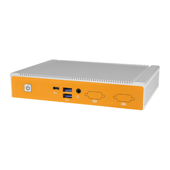
ML350G-10 Industrial Computer 5 - System Overview 5.1 - System Diagram Power Button USB C USB 3.0 Audio (Optional) In/Out Antenna Power In Gb LAN Gb LAN USB 2.0 Antenna (Optional) (Optional) (Optional) DisplayPort... -
Page 8: System Specifications
ML350G-10 Industrial Computer 5.2 - System Specifications N3350 N4200 Processor and Chipset Intel Apollo Lake with integrated graphics Memory 1 x 204-pin DDR3L SO-DIMM up to 8GB Audio Controller Realtek ALC283 audio codec Full-size/half-size mPCIe with PCIe, SATA, and USB signal Expansion Full-size mPCIe with PCIe and USB signal Full-size mPCIe with SATA and USB signal DisplayPort, Version 1.2 (HDMI CEC option, supports dual mode and MST) Rear I/O GbE LAN USB2.0 USB3.0 USB type C 3.1 Front I/O Audio jack; line-in/out... -
Page 9: Mounting Hole Pattern
ML350G-10 Industrial Computer 5.3 - Mounting Hole Pattern Ø4.6 mm Ø8 mm Ø4.5mm 12.7 mm 76.2 mm 210.6 mm 40.5 mm 3.7 mm 223.4 mm... -
Page 10: Mounting Guide
ML350G-10 Industrial Computer 5.4 - Mounting Guide Wall Mounting Step 1: Attach wall mount brackets to chassis Step 2: Mark and prep holes in surface for mounting Step 3: Fasten system to surface VESA Mounting Step 1: Install 4 VESA Screws into your display/surface Step 2: Attach VESA bracket to the chassis Step 3: Hang combined system and bracket to display/surface DIN Rail Mounting Step 1: Attach wall mounting brackets to the chassis... -
Page 11: Motherboard Overview
ML350G-10 Industrial Computer 6 - Motherboard Overview Audio USB 3.0 USB C Power Button In/Out DisplayPort 1 DisplayPort 2 LAN 2 LAN 1 Power In USB 2.0 (Optional) mPCIe/mSATA mSATA mPCIe Power In Header CEC Header Battery Header AT/ATX Jumper Memory Slot COM Header... -
Page 12: Jumpers And Headers Guide
ML350G-10 Industrial Computer 6.1 - Jumpers and Headers Guide Number Location Function J1_BIOS BIOS Load Default Header/Clear CMOS LAN 1 Connector LAN 2 Connector DisplayPort 1 DisplayPort 2 USB Type C Connector USB 3.0 Connector Audio Connector J9_CEC CEC Header USB 2.0 Connector USB 2.0 Connector J12_USB USB 2.0 Header... -
Page 13: Configuring Jumpers
ML350G-10 Industrial Computer Refer to the following diagrams for configuring jumpers and onboard headers. 6.2 - Configuring Jumpers J1_BIOS The J1_BIOS jumper loads the default BIOS settings. Short pins 2-3 for normal operation. Short pins 1-2 to clear the CMOS and reset the system setup configuration to default settings. If you experience challenges powering up, short pins 1-2 to troubleshoot. Clear CMOS Normal J13_AT_ATX AT = Auto power on. ATX = No auto power on. AT Mode ATX Mode... -
Page 14: Onboard Headers
ML350G-10 Industrial Computer 6.3 - Onboard Headers An onboard header is a connection on the motherboard that permits connecting a peripheral component to an external port on the system J9_CEC The ML350G-31 can be configured with a module that allows for CEC functionality. The J9_CEC connector includes wiring connections for the HDMI Consumer Electronics Control (CEC). -
Page 15: Uefi
ML350G-10 Industrial Computer J23_Ambient Header The J23_AMBIENT connector provides System Management Bus (SM Bus) communication. SMBus Clock SMBus Data J12_USB The J12_USB connector supports two USB ports. 5V_USB 5V_USB Data (Negative) Data (Negative) Data (Positive) Data (Positive) None XBT1_BATTERY and XBT2_BATTERY Connect the system and backup batteries to the XBT1_BATTERY and XBT2_BATTERY connectors. 7 - UEFI The ML350G-10 supports UEFI 64 bit only. UEFI updates can be downloaded directly from the system’s product page at http://www.onlogic.com/ml350g-10.
Need help?
Do you have a question about the ML350G-10 and is the answer not in the manual?
Questions and answers