
Related Manuals for Ultra Max UM1854-NAT


Summary of Contents for Ultra Max UM1854-NAT
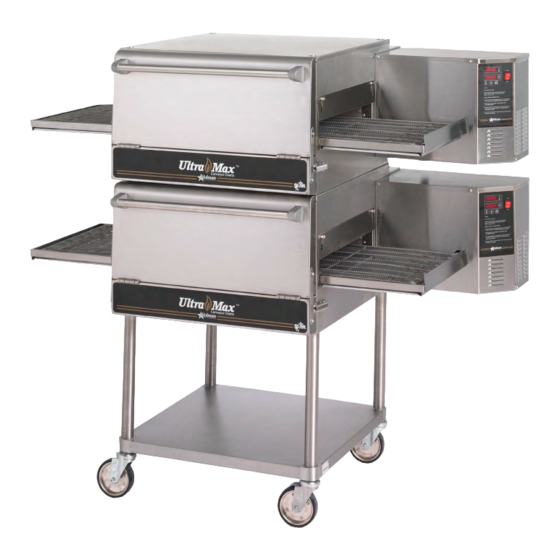
- Page 1 ® CONVEYOR OVEN Owner's Manual UM1854-NAT/-LP UM1854Q-NAT/-LP UM1854-NATCE 2M-Z5649 Rev. O 04/2018 UM1854...
-
Page 2: Safety Symbol
SAFETY SYMBOL These symbols are intended to alert the user to the presence of important operating and maintenance instructions in the manual accompanying the appliance. RETAIN THIS MANUAL FOR FUTURE REFERENCE NOTICE Service Help Desk Using any part other than genuine Star factory supplied parts relieves the Business 8:00 a.m. -
Page 3: Specifications
SPECIFICATIONS UM1854-NAT, UM1854-LP Gas Rating/Connection: 40,000 BTU 1/2" NPT male pipe connection Gas Supply Pressure: Natural - 5-6" water column (15-30 mBar) Propane - 11-12" water column (27.5-30 mBar) Electrical Supply: Separate 15 Amp 120VAC, single phase, 50/60 Hz service per Oven Approximate Weight (Single Oven with Cart): Installed - 280 Lbs (127.27 kg), Shipping - 350 Lbs (159.09 kg) -
Page 4: General Information
GENERAL INFORMATION This equipment is designed and sold for commercial use only by personnel trained and experienced in its operation and is not sold for consumer use in and around the home nor for use directly by the general public in food service locations. First and foremost, each crate should be examined before signing the Bill of Lading to report any visible damage by the trucker in transit and to account for the proper number of crates. -
Page 5: Purchaser's Responsibility
PURCHASER'S RESPONSIBILITY It is the responsibility of the purchaser: 1. To see that the gas and electric services for the oven are installed on site in accordance with the manufacturer's specifications. 2. To unload, uncrate, and install the oven in its proper location and in accordance with this installation operation manual. -
Page 6: Installation Information
INSTALLATION INFORMATION THE INSTALLATION INSTRUCTIONS CONTAINED HEREIN ARE FOR THE USE OF QUALIFIED INSTALLATION AND SERVICE PERSONNEL ONLY. INSTALLATION OR SERVICE BY OTHER THAN QUALIFIED PERSONNEL MAY RESULT IN DAMAGE TO THE OVEN AND/OR INJURY TO THE OPERATOR. Qualified installation personnel are individuals, a firm, a corporation, or a company which either in person or through a representative are engaged in and responsible for: 1. -
Page 7: Smoke Candle Test
VENTILATION A VENT IS REQUIRED: Local codes prevail. These are the "authority having jurisdiction" as stated by the National Fire Protection Association, Inc. in NFPA 96-Latest Edition. For further ventilation information see below. A ventilation hood is required to remove heat and cooking odors. For gas ovens, a ventilation hood is also required to remove the products of combustion. -
Page 8: Access Considerations
GAS SUPPLY RATING AND SIZING Calculations for pipe sizing must take into account the maximum usage rate of all other appliances in the kitchen or one or more of the appliances will suffer from inadequate or dangerous performance. The 1/2" NPT connection for the oven is generously sized for use in the control box of the oven. However, unless the oven installation is within 10 feet of the main building gas supply, the supply must be larger. -
Page 9: Stacking Instructions
WARNING: To prevent damage to the control valve regulator during the initial turn-on of gas, it is very important to open the manual shut-off valve very slowly. After the initial gas turn-on, the manual shut-off valve must remain open except during pressure testing as outlined in the above steps or when necessary during service maintenance. -
Page 10: Restraint Requirement
HOLLOW WALL STUD OR MASONRY WALL RESTRAINT REQUIREMENT 1. The installation shall be made with a gas connector that CAUTION complies with local codes for connectors for movable DO NOT WORK AROUND THE CONVEYOR gas appliances and a quick-disconnect device that BELT WITH LONG HAIR, LOOSE CLOTHING, complies with local codes for such devices in use OR DANGLING JEWELRY. -
Page 11: Safety Tips
Please take time to read the following safety operating instructions. They are the key to the successful operation of your Ultra-Max Conveyor Oven. General Safety Tips: SAFETY TIPS 1. If the oven needs to be moved for any reason, the power must be disconnected from the unit For your safety, read before operating. -
Page 12: Display Information
DISPLAY INFORMATION ADDITIONAL FUNCTIONS The conveyor belt direction and the temperature display can When operating the oven, there are different be changed on the conveyor oven by a qualified technician. levels of access: To change the belt direction, the technician must reverse the 1. -
Page 13: Conveyor Speed
BAKE TIME VERSUS TEMPERATURE CONVEYOR SPEED Bake Time (Conveyor Speed) - As stated previously, bake 1. Bake time is actually conveyor speed and is defined time (conveyor speed) is defined as the amount of time as the time the product is actually in the oven. This is elapsed between the time the leading edge of the product measured by noting the time when the leading edge of enters the oven and the leading edge of the product exits... -
Page 14: Maintenance Instructions
MAINTENANCE INSTRUCTIONS DISCONNECT THE POWER SUPPLY BEFORE SERVICING OR CLEANING THIS OVEN. SAFEGUARD THE POWER SO IT CANNOT BE ACCIDENTALLY RESTORED. FAILURE TO DO SO COULD RESULT IN DISMEMBERMENT, ELECTROCUTION, WARNING OR FATAL INJURY. THERE IS MORE THAN ONE POWER SUPPLY CONNECTION POINT WHEN OVENS ARE STACKED, SO MAKE SURE THAT ALL SWITCHES ARE IN THE OFF POSITION BEFORE CLEANING OR MAINTENANCE. - Page 15 DIRECTIONS FOR DISASSEMBLY 1. Remove crumb trays and 2. Push the spring-loaded coupling 3. Lift up the left end of the conveyor shelves from both ends. in to disengage the pin in the frame so the crumb tray supports shaft. Rotate the shaft so the pin clear the tunnel opening.
-
Page 16: Conveyor Belt Tension
CONVEYOR BELT TENSION The conveyor belt of the Ultra-Max Gas Conveyor Oven does not have a tension adjustment. If the belt becomes too loose, a link will have to be removed to tighten. A belt that is too tight will also cause operational problems due to excessive drag. -
Page 20: Parts List
PARTS LIST August 25, 2011, Rev. M Ultra-Max Gas Conveyor Oven UM1854-NAT/LP CONTROL BOX Description G9-GC0013 CONTROL BOX DOOR PS-Z7718 TIME & TEMP CONTROLLER GAS OVEN 120V G9-Z5250 POWER SUPPLY BRACKET G9-Z5251 OBSOLETE GEARMOTOR BRACKET G9-Z13295 GEARMOTOR MOUNT BRACKET (FROM 07/27/10) - Page 22 PARTS LIST Ultra-Max Gas Conveyor Oven UM1854-NATCE - Control Box MODEL Number Part Description Number Number Unit G9-GC0013 CONTROL BOX DOOR TIME & TEMP CONTROLLER (GAS OVEN, 230V) G9-Z6606 POWER SUPPLY BRACKET G9-Z5250 GEARMOTOR BRACKET (OBSOLETE) G9-Z5251 G9-Z13295 GEARMOTOR BRACKET (FROM 04-2018) CONTROL BOX LID G9-Z5249 THERMOSTAT, COOL DOWN, 120°F 2T-Z5175 THERMOSTAT, HI-LIMIT, 140°F 2T-Z5176 HIGH TEMPERATURE LIMIT 2T-Z5177 10AMP CIRCUIT BREAKER 2E-Z5206 VACUUM SWITCH 2E-Z5683 LIGHTED SWITCH 2E-Z1858 POWER RESISTOR 2E-Z5642 POWER RESISTOR BRACKETS...
- Page 24 PARTS LIST August 25, 2011, Rev. M Ultra-Max Gas Conveyor Oven UM1854-NAT/LP MAIN ASSEMBLY Fig No Part No Description Application 2C-Z3780 CONDUIT RETAINER 2R-Z5188 LATCH KEEPER 2R-Z5174 LATCH G9-Z5309 DOOR BRACE 2P-09-WB-0003 PLUG CAP 2V-Z5293 HANDLE TUBE 2R-Z5279 HANDLE SUPPORT (PAIR)
- Page 26 PARTS LIST August 25, 2011, Rev. M Ultra-Max Gas Conveyor Oven UM1854-NAT/LP FINGER ASSEMBLY Fig No Part No Description Application G9-Z5516 LOWER FINGER BAFFLE G9-GC0037 LOWER FINGER DIVERTER ASSEMBLY G9-GC0035 LOWER FINGER WELDMENT G9-GC0043 LOWER COLUMNATING PLATE G9-Z5432 LOWER-FULL NOZZLE, PLATE...
- Page 27 LIMITED EQUIPMENT WARRANTY WARRANTY EXCLUSIONS THE FOLLOWING WILL NOT BE COVERED UNDER WARRANTY. Star Manufacturing [as well as its subsidiaries] warranties new products • Any product which has not been used, cleaned, maintained, to be free from defects in material and/or workmanship for a period or installed in accordance with the directions published in the of one [1] year from the date of original installation, except as noted appropriate installation sheet and/or owner's manual as well...
Need help?
Do you have a question about the UM1854-NAT and is the answer not in the manual?
Questions and answers