Table of Contents
Advertisement
Quick Links
Advertisement
Table of Contents

Related Manuals for Texas Instruments TPS53316EVM-075


Summary of Contents for Texas Instruments TPS53316EVM-075
- Page 1 Using the TPS53316EVM-075 User's Guide Literature Number: SLUU671 December 2011...
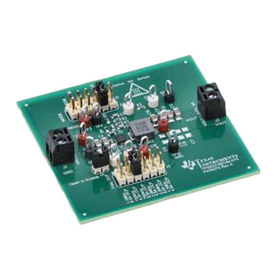
- Page 2 TPS53316 is a fully integrated step-down regulator employing voltage mode control. Description The TPS53316EVM-075 is designed to use a 3.3-V or 5-V voltage rail to produce a regulated 1.5-V output at up to 5-A load current. The TPS53316EVM-075 is designed to demonstrate the TPS53316 in a typical low voltage application while providing a number of test points to evaluate the performance of the TPS53316.
-
Page 3: Electrical Performance Specifications
Electrical Performance Specifications www.ti.com Electrical Performance Specifications Table 1. TPS53316EVM-075 Electrical Performance Specifications PARAMETER TEST CONDITIONS UNITS Input Characteristics Voltage range 3.3/5.0 Maximum input current = 5 V, I = 5 A 1.76 No load input current = 5 V, I... - Page 4 Schematic www.ti.com Schematic Figure 1. TPS53316EVM-075 Schematic SLUU671 – December 2011 5-A Step-Down Regulator with Integrated Switcher Submit Documentation Feedback Copyright © 2011, Texas Instruments Incorporated...
- Page 5 J3 to LOAD: The minimum recommended wire size is 1x AWG #14, with the total length of wire less than 4 feet (2 feet output, 2 feet return) SLUU671 – December 2011 5-A Step-Down Regulator with Integrated Switcher Submit Documentation Feedback Copyright © 2011, Texas Instruments Incorporated...
-
Page 6: Recommended Test Setup
Recommended Test Setup Figure 3 is the recommended test set up to evaluate the TPS53316EVM-075. Working at an ESD workstation, make sure that any wrist straps, bootstraps or mats are connected referencing the user to earth ground before power is applied to the EVM. -
Page 7: Mode Selection
750 kHz 6.5 A 105 kΩ 2.0 MHz 4.5 A 174 kΩ 2.0 MHz 6.5 A Open 1.1 MHz 4.5 A SLUU671 – December 2011 5-A Step-Down Regulator with Integrated Switcher Submit Documentation Feedback Copyright © 2011, Texas Instruments Incorporated... - Page 8 10. Decrease Load to 0 A. 11. Decrease VIN to 0 V. Control Loop Gain and Phase Measurement Procedure TPS53316EVM-075 contains a 10-Ω series resistor in the feedback loop for loop response analysis. 1. Set up EVM as described in Section 5 Figure 2.
-
Page 9: List Of Test Points
TP11 Enable Pin TP12 Power Good Output Equipment Shutdown 1. Shut down VIN. 2. Shut down Load. 3. Shut down FAN. SLUU671 – December 2011 5-A Step-Down Regulator with Integrated Switcher Submit Documentation Feedback Copyright © 2011, Texas Instruments Incorporated... -
Page 10: Performance Data And Typical Characteristic Curves
Performance Data and Typical Characteristic Curves www.ti.com Performance Data and Typical Characteristic Curves Figure 4 through Figure 19 present typical performance curves for TPS53316EVM-075. Efficiency VIN = 3.3 V, FCCM, fsw = 750 kHz VIN = 3.3 V, DE Mode, fsw = 750 kHz VIN = 3.3 V, HEF Mode, fsw = 750 kHz... -
Page 11: Load Regulation
HEF Mode, fsw = 2.0 MHz, Iout = 0 A HEF Mode, fsw = 2.0 MHz, Iout = 5 A 1.49 - Input Voltage - V Figure 7. Line Regulation SLUU671 – December 2011 5-A Step-Down Regulator with Integrated Switcher Submit Documentation Feedback Copyright © 2011, Texas Instruments Incorporated... - Page 12 (5-V VIN, 1.5-V VOUT, FCCM, fsw = 750 kHz ) Figure 9. Load 0-3A Transient under HEF Mode (5-V VIN, 1.5-V VOUT, HEF Mode, fsw = 750 kHz ) SLUU671 – December 2011 5-A Step-Down Regulator with Integrated Switcher Submit Documentation Feedback Copyright © 2011, Texas Instruments Incorporated...
-
Page 13: Output Ripple
(5-V VIN, 1.5-V VOUT, 5-A, FCCM, fsw = 750 kHz) Figure 11. Output Ripple (5-V VIN, 1.5-V VOUT, 0-A, HEF Mode, fsw = 750 kHz ) SLUU671 – December 2011 5-A Step-Down Regulator with Integrated Switcher Submit Documentation Feedback Copyright © 2011, Texas Instruments Incorporated... - Page 14 (5-V VIN, 1.5-V VOUT, 5-A, FCCM, fsw = 750 kHz ) Figure 13. Switching Node (5-V VIN, 1.5-V VOUT, 0-A, HEF Mode, fsw = 750 kHz ) SLUU671 – December 2011 5-A Step-Down Regulator with Integrated Switcher Submit Documentation Feedback Copyright © 2011, Texas Instruments Incorporated...
- Page 15 Figure 14. Turn-On Waveform ( 5-V VIN, 1.5-V VOUT, 5-A IOUT, 4XS.S.) Figure 15. Turn-Off Waveform ( 5-V VIN, 1.5-V VOUT, 0-A IOUT ) SLUU671 – December 2011 5-A Step-Down Regulator with Integrated Switcher Submit Documentation Feedback Copyright © 2011, Texas Instruments Incorporated...
-
Page 16: Overcurrent Protection
( 5-V VIN, 1.5-V VOUT, 0-A IOUT, 4XS.S., 0.5-V pre-bias) Overcurrent Protection Figure 17. Overcurrent Protection Waveform ( 3.3-V VIN, 1.5-V VOUT, 6.5-A IOUT, 4XS.S., 750 kHz, 6.5-A OCP) SLUU671 – December 2011 5-A Step-Down Regulator with Integrated Switcher Submit Documentation Feedback Copyright © 2011, Texas Instruments Incorporated... -
Page 17: Thermal Image
= 750 kHz) 8.11 Thermal Image Figure 19. Thermal Image (6-V VIN, 1.5-V VOUT, 5-A IOUT, FCCM Mode, f = 2.0 MHz) SLUU671 – December 2011 5-A Step-Down Regulator with Integrated Switcher Submit Documentation Feedback Copyright © 2011, Texas Instruments Incorporated... -
Page 18: Evm Assembly Drawing And Pcb Layout
25) show the design of the TPS53316EVM-075 printed circuit board. The EVM has been designed using a 4-layer, 2-oz copper circuit board. Figure 20. TPS53316EVM-075 Top Layer Assembly Drawing (top view) SLUU671 – December 2011 5-A Step-Down Regulator with Integrated Switcher Submit Documentation Feedback Copyright ©... - Page 19 EVM Assembly Drawing and PCB Layout www.ti.com Figure 21. TPS53316EVM-075 Bottom Assembly Drawing (bottom view) Figure 22. TPS53316EVM-075 Top Copper (top view) SLUU671 – December 2011 5-A Step-Down Regulator with Integrated Switcher Submit Documentation Feedback Copyright © 2011, Texas Instruments Incorporated...
- Page 20 EVM Assembly Drawing and PCB Layout www.ti.com Figure 23. TPS53316EVM-075 Layer 2 (top view) Figure 24. TPS53316EVM-075 Layer 3 (top view) SLUU671 – December 2011 5-A Step-Down Regulator with Integrated Switcher Submit Documentation Feedback Copyright © 2011, Texas Instruments Incorporated...
- Page 21 EVM Assembly Drawing and PCB Layout www.ti.com Figure 25. TPS53316EVM-075 Bottom Layer (top view) SLUU671 – December 2011 5-A Step-Down Regulator with Integrated Switcher Submit Documentation Feedback Copyright © 2011, Texas Instruments Incorporated...
-
Page 22: List Of Materials
List of Materials www.ti.com List of Materials The EVM components list according to the schematic shown in Figure Table 5. TPS53316EVM-075 List of Materials REF DES DESCRIPTION PART NUMBER C1, C2 Capacitor, ceramic, 50 V, X7R, 10%, 3.3 nF, 603 Capacitor, ceramic, 50 V, X7R, 10%, 100 pF, 603 Capacitor, ceramic, 16 V, X7R, 15%, 1.0 µF, 603... -
Page 23: Evaluation Board/Kit Important Notice
Evaluation Board/Kit Important Notice Texas Instruments (TI) provides the enclosed product(s) under the following conditions: This evaluation board/kit is intended for use for ENGINEERING DEVELOPMENT, DEMONSTRATION, OR EVALUATION PURPOSES ONLY and is not considered by TI to be a finished end-product fit for general consumer use. Persons handling the product(s) must have electronics training and observe good engineering practice standards. -
Page 24: Regulatory Compliance Information
Any exceptions to this are strictly prohibited and unauthorized by Texas Instruments unless user has obtained appropriate experimental/development licenses from local regulatory authorities, which is responsibility of user including its acceptable authorization. - Page 25 FCC Interference Statement for Class B EVM devices This equipment has been tested and found to comply with the limits for a Class B digital device, pursuant to part 15 of the FCC Rules. These limits are designed to provide reasonable protection against harmful interference in a residential installation. This equipment generates, uses and can radiate radio frequency energy and, if not installed and used in accordance with the instructions, may cause harmful interference to radio communications.
- Page 26 Also, please do not transfer this product, unless you give the same notice above to the transferee. Please note that if you could not follow the instructions above, you will be subject to penalties of Radio Law of Japan. Texas Instruments Japan Limited (address) 24-1, Nishi-Shinjuku 6 chome, Shinjuku-ku, Tokyo, Japan http://www.tij.co.jp...
- Page 27 FDA Class III or similar classification, then you must specifically notify TI of such intent and enter into a separate Assurance and Indemnity Agreement. Mailing Address: Texas Instruments, Post Office Box 655303, Dallas, Texas 75265 Copyright © 2012, Texas Instruments Incorporated...
-
Page 28: Important Notice
IMPORTANT NOTICE Texas Instruments Incorporated and its subsidiaries (TI) reserve the right to make corrections, enhancements, improvements and other changes to its semiconductor products and services per JESD46, latest issue, and to discontinue any product or service per JESD48, latest issue.
Need help?
Do you have a question about the TPS53316EVM-075 and is the answer not in the manual?
Questions and answers