Table of Contents
Advertisement
Quick Links
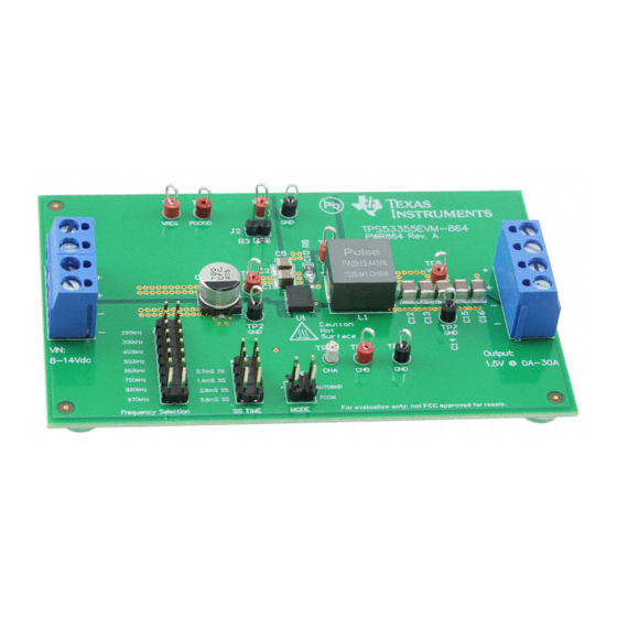
The TPS53355EVM-864 evaluation module (EVM) allows users to evaluate the TPS53355. The
TPS53355 is a D-CAP™ mode, 30-A synchronous buck converter with integrated MOSFETs. It provides a
fixed 1.5-V output at up to 30 A from a 12-V input bus.
...................................................................................................................
1
1.1
....................................................................................................................
2
2.1
2.2
3
.....................................................................................................................
4
....................................................................................................................
5
5.1
5.2
6
6.1
6.2
6.3
6.4
7
7.1
7.2
7.3
7.4
8
8.1
8.2
8.3
8.4
8.5
8.6
8.7
8.8
8.9
8.10
8.11
8.12
9
10
1
2
3
....................................................................................................................
4
Efficiency
Green TPS53355EVM-864 Evaluation Module
...................................................................................................
................................................................................................
..............................................................................................................
.....................................................................................
.....................................................................................................
........................................................................................
................................................................................................................
...................................................................................
.................................................................................................
......................................................................................................
...................................................................................................
...............................................................................................................
......................................................................................................
.............................................................................................
...........................................................................................................
...................................................................................................
....................................................................................................
............................................................................................
.....................................................................................................
....................................................................................................
...................................................................................
...........................................................................................................
.....................................................................................................
..............................................................................
.............................................................................................................
............................................................................................
Copyright © 2016, Texas Instruments Incorporated
Contents
..............................................
......................................................
.................................................................
........................................................................
............................................................................
..............................................................
List of Figures
..........................................................................
........................................................................
User's Guide
SLUUBJ6 - November 2016
3
3
4
4
4
4
5
6
6
7
8
8
8
8
9
9
9
9
10
10
11
11
11
12
12
13
13
14
14
15
15
16
17
18
22
5
6
7
11
1
Advertisement
Table of Contents

Related Manuals for Texas Instruments TPS53355EVM-864


Summary of Contents for Texas Instruments TPS53355EVM-864
-
Page 1: Table Of Contents
SLUUBJ6 – November 2016 Green TPS53355EVM-864 Evaluation Module The TPS53355EVM-864 evaluation module (EVM) allows users to evaluate the TPS53355. The TPS53355 is a D-CAP™ mode, 30-A synchronous buck converter with integrated MOSFETs. It provides a fixed 1.5-V output at up to 30 A from a 12-V input bus. - Page 2 Test Point Functions ..............EVM Components List (see Schematic Figure 1) Trademarks D-CAP is a trademark of Texas Instruments. All other trademarks are the property of their respective owners. Green TPS53355EVM-864 Evaluation Module SLUUBJ6 – November 2016 Submit Documentation Feedback...
-
Page 3: Introduction
EVM. Also be aware that the computer is referenced to the Battery- potential of the EVM. SLUUBJ6 – November 2016 Green TPS53355EVM-864 Evaluation Module Submit Documentation Feedback Copyright © 2016, Texas Instruments Incorporated... -
Page 4: Description
The TPS53355EVM-864 is designed to use a regulated 12-V bus to produce a regulated 1.5-V output at up to 30 A of load current. The TPS53355EVM-864 is designed to demonstrate the TPS53355 in a typical, low-voltage application while providing a number of test points to evaluate the performance of the TPS53355. -
Page 5: Schematic
Schematic www.ti.com Schematic Figure 1 illustrates the EVM schematic. Figure 1. TPS53355EVM-864 Schematic SLUUBJ6 – November 2016 Green TPS53355EVM-864 Evaluation Module Submit Documentation Feedback Copyright © 2016, Texas Instruments Incorporated... -
Page 6: Test Setup
The minimum recommended wire size is 2x AWG 14, with the total length of wire less than 4 feet (2- foot output, 2-foot return) Green TPS53355EVM-864 Evaluation Module SLUUBJ6 – November 2016 Submit Documentation Feedback Copyright © 2016, Texas Instruments Incorporated... -
Page 7: Recommended Test Setup
Recommended Test Setup Figure 3 is the recommended test setup to evaluate the TPS53355EVM-864. Working at an ESD workstation, ensure that any wrist straps, bootstraps, or mats are connected referencing the user to earth ground before power is applied to the EVM. -
Page 8: Configurations
Default setting: Auto Skip Table 4. MODE Selection Jumper Set to MODE Selection Top (1–2 pin shorted) Auto Skip Bottom (7–8 pin shorted) Forced CCM Green TPS53355EVM-864 Evaluation Module SLUUBJ6 – November 2016 Submit Documentation Feedback Copyright © 2016, Texas Instruments Incorporated... -
Page 9: Enable Selection
11. Decrease Load to 0 A 12. Decrease V to 0 V. Control Loop Gain and Phase Measurement Procedure TPS53355EVM-864 contains a 10-Ω series resistor in the feedback loop for loop response analysis. 1. Set up the EVM as described in Section 5 Figure 2. -
Page 10: Test Point List
TP10 Input A for loop injection TP11 Input B for loop injection TP12 Equipment Shutdown 1. Shut down Load. 2. Shut down fan. Green TPS53355EVM-864 Evaluation Module SLUUBJ6 – November 2016 Submit Documentation Feedback Copyright © 2016, Texas Instruments Incorporated... -
Page 11: Performance Data And Typical Characteristic Curves
Performance Data and Typical Characteristic Curves www.ti.com Performance Data and Typical Characteristic Curves Figure 4 through Figure 18 present typical performance curves for TPS53355EVM-864. Efficiency 12 Vin auto skip 8 Vin auto skip 14 Vin auto skip 8 Vin FCCM... -
Page 12: Line Regulation
Auto Skip Mode CH1: EN CH1: EN CH2: 1.5 Vout CH2: 1.5 Vout CH3: PGOOD CH3: PGOOD Figure 7. Enable Turnon Figure 8. Enable Turnoff Green TPS53355EVM-864 Evaluation Module SLUUBJ6 – November 2016 Submit Documentation Feedback Copyright © 2016, Texas Instruments Incorporated... -
Page 13: Output Ripple
Figure 9. Output Ripple Switching Node TPS5335EVM Test condition: 12 Vin, 1.5 V/30 A Switching Node Auto Skip Mode CH1: LL Figure 10. Switching Node SLUUBJ6 – November 2016 Green TPS53355EVM-864 Evaluation Module Submit Documentation Feedback Copyright © 2016, Texas Instruments Incorporated... -
Page 14: Output Transient With Auto-Skip Mode
Output Transient from 0 A to 15 A FCCM Mode CH1: 1.5 Vout CH4: output Current Figure 13. Output Transient With FCCM Mode Green TPS53355EVM-864 Evaluation Module SLUUBJ6 – November 2016 Submit Documentation Feedback Copyright © 2016, Texas Instruments Incorporated... -
Page 15: Output 0.75-V Prebias Turnon
8.10 Output Overcurrent and Short-Circuit Protection TPS53355EVM Test Condition: 12 Vin OCP Over Current Protection Ch1: 1.5 Vout Ch2: LL Ch3: PGOOD Figure 15. Output Overcurrent Protection SLUUBJ6 – November 2016 Green TPS53355EVM-864 Evaluation Module Submit Documentation Feedback Copyright © 2016, Texas Instruments Incorporated... -
Page 16: 8.11 Bode Plot
8.11 Bode Plot Figure 17. Bode Plot, V = 12 V, V = 1.5 V, I = 6 A, Frequency = 500 kHz Green TPS53355EVM-864 Evaluation Module SLUUBJ6 – November 2016 Submit Documentation Feedback Copyright © 2016, Texas Instruments Incorporated... -
Page 17: 8.12 Thermal Image
Figure 18. Top Board at 12 V , 1.5 V/30 A, 25°C Ambient Temperature Without Airflow SLUUBJ6 – November 2016 Green TPS53355EVM-864 Evaluation Module Submit Documentation Feedback Copyright © 2016, Texas Instruments Incorporated... -
Page 18: Evm Assembly Drawing And Pcb Layout
EVM Assembly Drawing and PCB Layout The following illustrations (Figure 19 through Figure 26) show the design of the TPS53355EVM-864 printed-circuit board. The EVM was designed using a 6-layer, 2-oz copper circuit board. EXAS NSTRUMENTS Figure 19. TPS53355EVM-864 Top Layer Assembly Drawing Figure 20. -
Page 19: Tps53355Evm-864 Top Copper
EVM Assembly Drawing and PCB Layout www.ti.com Figure 21. TPS53355EVM-864 Top Copper Figure 22. TPS53355EVM-864 Layer-2 Copper SLUUBJ6 – November 2016 Green TPS53355EVM-864 Evaluation Module Submit Documentation Feedback Copyright © 2016, Texas Instruments Incorporated... -
Page 20: Tps53355Evm-864 Layer-3 Copper
EVM Assembly Drawing and PCB Layout www.ti.com Figure 23. TPS53355EVM-864 Layer-3 Copper Figure 24. TPS53355EVM-864 Layer-4 Copper Green TPS53355EVM-864 Evaluation Module SLUUBJ6 – November 2016 Submit Documentation Feedback Copyright © 2016, Texas Instruments Incorporated... -
Page 21: Tps53355Evm-864 Layer-5 Copper
EVM Assembly Drawing and PCB Layout www.ti.com Figure 25. TPS53355EVM-864 Layer-5 Copper Figure 26. TPS53355EVM-864 Bottom Layer Copper SLUUBJ6 – November 2016 Green TPS53355EVM-864 Evaluation Module Submit Documentation Feedback Copyright © 2016, Texas Instruments Incorporated... -
Page 22: Bill Of Materials
0603 619k CRCW0603619KFKEA Vishay-Dale RES, 619 k, 1%, 0.1 W, 0603 0603 200k CRCW0603200KFKEA Vishay-Dale RES, 200 k, 1%, 0.1 W, 0603 0603 Green TPS53355EVM-864 Evaluation Module SLUUBJ6 – November 2016 Submit Documentation Feedback Copyright © 2016, Texas Instruments Incorporated... -
Page 23: Submit Documentation Feedback
High-Efficiency 30 A Synchronous Buck Converter with Eco-mode, VQP0022A (LSON-CLIP- VQP0022A FID1, FID2, Fiducial mark. There is nothing to buy or mount. FID3, FID4, FID5, FID6 SLUUBJ6 – November 2016 Green TPS53355EVM-864 Evaluation Module Submit Documentation Feedback Copyright © 2016, Texas Instruments Incorporated... - Page 24 STANDARD TERMS AND CONDITIONS FOR EVALUATION MODULES Delivery: TI delivers TI evaluation boards, kits, or modules, including demonstration software, components, and/or documentation which may be provided together or separately (collectively, an “EVM” or “EVMs”) to the User (“User”) in accordance with the terms and conditions set forth herein.
- Page 25 FCC Interference Statement for Class B EVM devices NOTE: This equipment has been tested and found to comply with the limits for a Class B digital device, pursuant to part 15 of the FCC Rules. These limits are designed to provide reasonable protection against harmful interference in a residential installation.
- Page 26 【無線電波を送信する製品の開発キットをお使いになる際の注意事項】 開発キットの中には技術基準適合証明を受けて いないものがあります。 技術適合証明を受けていないもののご使用に際しては、電波法遵守のため、以下のいずれかの 措置を取っていただく必要がありますのでご注意ください。 1. 電波法施行規則第6条第1項第1号に基づく平成18年3月28日総務省告示第173号で定められた電波暗室等の試験設備でご使用 いただく。 2. 実験局の免許を取得後ご使用いただく。 3. 技術基準適合証明を取得後ご使用いただく。 なお、本製品は、上記の「ご使用にあたっての注意」を譲渡先、移転先に通知しない限り、譲渡、移転できないものとします。 上記を遵守頂けない場合は、電波法の罰則が適用される可能性があることをご留意ください。 日本テキサス・イ ンスツルメンツ株式会社 東京都新宿区西新宿6丁目24番1号 西新宿三井ビル 3.3.3 Notice for EVMs for Power Line Communication: Please see http://www.tij.co.jp/lsds/ti_ja/general/eStore/notice_02.page 電力線搬送波通信についての開発キットをお使いになる際の注意事項については、次のところをご覧ください。http:/ /www.tij.co.jp/lsds/ti_ja/general/eStore/notice_02.page SPACER EVM Use Restrictions and Warnings: 4.1 EVMS ARE NOT FOR USE IN FUNCTIONAL SAFETY AND/OR SAFETY CRITICAL EVALUATIONS, INCLUDING BUT NOT LIMITED TO EVALUATIONS OF LIFE SUPPORT APPLICATIONS.
- Page 27 Notwithstanding the foregoing, any judgment may be enforced in any United States or foreign court, and TI may seek injunctive relief in any United States or foreign court. Mailing Address: Texas Instruments, Post Office Box 655303, Dallas, Texas 75265 Copyright © 2016, Texas Instruments Incorporated...
- Page 28 IMPORTANT NOTICE Texas Instruments Incorporated and its subsidiaries (TI) reserve the right to make corrections, enhancements, improvements and other changes to its semiconductor products and services per JESD46, latest issue, and to discontinue any product or service per JESD48, latest issue.
- Page 29 Mouser Electronics Authorized Distributor Click to View Pricing, Inventory, Delivery & Lifecycle Information: Texas Instruments TPS53355EVM-864...
Need help?
Do you have a question about the TPS53355EVM-864 and is the answer not in the manual?
Questions and answers